Table of Contents
Advertisement
Quick Links
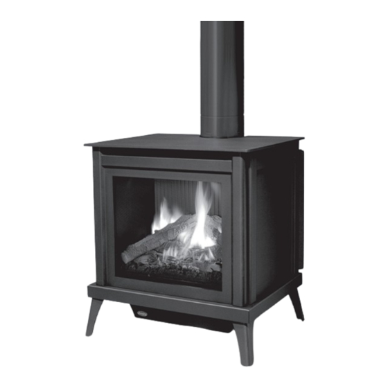
S40I / S40ID
F R E E S T A N D I N G G A S F I R E P L A C E
OWNER'S MANUAL
WARNING:
If the information in this manual is not followed exactly, a
fire or explosion may result causing property damage, personal injury
or loss of life. Installation and service must be performed by a qualified
installer, service agency or the gas supplier.
C#4001609
50-4052
Version Française: www.enviro.com/fr.html
Advertisement
Table of Contents

Related Manuals for Enviro S40I


Summary of Contents for Enviro S40I
- Page 1 S40I / S40ID F R E E S T A N D I N G G A S F I R E P L A C E OWNER’S MANUAL WARNING: If the information in this manual is not followed exactly, a fire or explosion may result causing property damage, personal injury or loss of life.
-
Page 2: Safety Precautions
Safety Precautions WARNING: FIRE OR EXPLOSION HAZARD Failure to follow safety warnings exactly could result in serious injury, death, or property damage. - Do not store or use gasoline or other flammable vapors and liquids in the vicinity of this or any other appliance. - WHAT TO DO IF YOU SMELL GAS •... - Page 3 NEVER ALLOW CHILDREN shut. TO TOUCH GLASS. • If the S40I / S40ID unit is pulled out of its installation, and A barrier designed to reduce the risk of burns from the the vent-air intake system is disconnected for any reason,...
-
Page 4: Table Of Contents
Table of Contents Safety Precautions......................2 Table of Contents......................4 Codes And Approvals....................5 Specifications....................6 Dimensions.....................6 Rating Label Location..................6 Operating Instructions.....................7 Lighting Instructions..................7 Air Shutter......................8 Normal Sounds During Operation................8 Transmitter.................9 Initializing the System for the First Time.............11 Switching to Continuous Pilot................11 Turn off the Appliance..................12 Room Thermostat....................12 Remote Flame Control..................12 Fan Control.....................13... -
Page 5: Codes And Approvals
After the unit has gone through the first burn, turn the unit off including the pilot, let the unit get cold then remove the glass door and clean it with a good gas fireplace glass cleaner, available at your local ENVIRO dealer. -
Page 6: Specifications
[77 cm] [72.7 cm] 22 7/16" [57 cm] 26 1/8" [66.4 cm] 4 5/8" [11.7 cm] Figure 1. S40I / S40ID Dimensions & L ating abeL ighting nstRuctions ocation The rating label and lighting instructions are located on a plate hanging on the back of of the unit. -
Page 7: Operating Instructions
Operating Instructions For Your Safety, Read Safety Precautions And Lighting Instructions Before Operating WARNING: IF YOU DO NOT FOLLOW THESE INSTRUCTIONS EXACTLY A FIRE OR EXPLOSION MAY RESULT, CAUSING PROPERTY DAMAGE, PERSONAL INJURY OF LOSS OF LIFE. ighting anD uRning nstRuctions FOR YOUR SAFETY READ BEFORE OPERATING WARNING:... -
Page 8: Air Shutter
Proflame 2 is a modular remote control system that directs the functions of the S40I. The Proflame 2 TMFSLA is configured to control the on/off main burner operation, its flame levels and provides on/off and Smart thermostatic control of the appliance. The system also controls the fan speed through six (6) -
Page 9: Transmitter
Operating Instructions For S40ID models refer to the separate Dexen user manual supplied for remote control operations. ystem escRiption The Proflame 2 Remote Control System consists of two (2) elements: 1. Proflame 2 Transmitter. 2. Integrated Fireplace Controller (IFC) and wiring harness to connect to the gas valve, stepper motor battery holder, convection fan, and lights. - Page 10 Operating Instructions Key Lock Transmission Low battery alarm Thermostat OFF/ Room ON/SMART Temperature CPI mode Set Point Aux ON Temperature/Level/State Flame ON Split Flow Dimmer ON Comfort fan Figure 5: Proflame 2 Transmitter LCD Screen. (ifc): ntegRateD iRepLace ontRoLLeR The Proflame 2 IFC (Figure 6) connects directly to the gas valve, split flow valve, stepper motor, pilot and covection fan with a wiring harness.
-
Page 11: Initializing The System For The First Time
When the S40I is turned off press the mode key to index to the constant pilot (CPI) mode icon (see figure 8). Pressing the up arrow key will select Continuous Pilot Ignition (CPI) and pressing the down arrow key will return to IPI. -
Page 12: Turn Off The Appliance
Operating Instructions Turn off the Appliance Room Temperature Press the ON/OFF Key on the Transmitter. The Transmitter LCD display will only show the room temperature and Icon (see Figure 7). A single “beep” from the IFC confirms reception of the command and both the pilot light (if the unit is not set to continuous pilot) and main burner will turn off. -
Page 13: Fan Control
Operating Instructions Split Flow Operation This function is not used on the S40I and can be disregarded. Figure 12: Split Flow Control (not used) Fan Control The S40I comes with a convection fan that can be controlled with the Transmitter. The fan speed can be adjusted thorugh six (6) speeds. -
Page 14: Key Lock
Operating Instructions Key lock This function will lock the keys to avoid unsupervised operation. To activate this function, press the Mode and UP keys at the same time and the a lock will appear (see Figure 16). To de-activate this function, press the Mode and UP Keys at the same time. -
Page 15: Maintenance And Service
The glass must be purchased from an ENVIRO dealer. No substitute materials are allowed. Remove the door (see page 16). The replacement glass will come with a new gasket installed. Remove any silicone remnants from the door. -
Page 16: Cabinet Front Removal
Ront emovaL Top Plate The cabinet front on the S40I / S40ID needs to be removed whenever access to the firebox is required. First the S40I / S40ID must be turned off and allowed to fully cool. Next, remove the Top Plate as shown in Figure 18 by lifting up and out. -
Page 17: Burner Removal
Maintenance And Service uRneR emovaL The burner may need to be removed for a few reasons, including cleaning under the burner, converting the unit to a different gas type, or to replace the burner altogether. Proceed only when the unit has completely cooled down. -
Page 18: Fuel Conversion
Kit Parts List for all Berkeley-IPI & S40I models: 2 - Burner Orifice (LP: 2 x #55 , 1 x #56) 1 - LP Pilot Orifice... - Page 19 If the S40I has been installed at an altitude higher than 2000ft (610m) it is required to estIng de-rate the unit accordingly. If converting to Propane use the supplied #56 orifice on the left : In the USA: The appliance may be installed at higher altitudes. Please refer to your American Gas...
-
Page 20: Initial Installation
• Locate the stove in a large and open room that is centrally located in the house. This will optimize heat circulation and comfort. • As the S40I / S40ID is equipped with a convection fan, ensure that an electrical outlet is within 6 ft (1.8 m) of the stove. -
Page 21: Direct Vent
The vent length for the S40I / S40ID must be between 36” (91 cm) and 44ft (13.4 m). This model is vented with co-axial 4” intake, 6 5/8” exhaust aluminum or stainless steel approved rigid vent leading into a vertical or horizontal termination cap. - Page 22 Initial Installation QUALIFIED INSTALLERS ONLY WARNING: Do not mix parts from different vent manufacturers’ systems. EXCEPTION TO WARNING: This product has been evaluated by Intertek for using a DirectVent Pro starting collar in conjunction with other venting systems. Use of this system with the DirectVent Pro starting collar is deemed acceptable and does not affect the Intertek listing of the appliance.
-
Page 23: Horizontal Termination - Minimum Vent
Refer to the figure for below for the minimum allowable venting setup for the S40I / S40ID. A termination guard (50-3266) is required when the termination is within 7’ (2.13m) of grade. Approved horizontal termination Approved through... -
Page 24: Vent Termination Restrictions
Initial Installation QUALIFIED INSTALLERS ONLY eRmination estRictions Fixed Closed Fixed Openable Closed Openable Termination Cap Air Supply Inlet Gas Meter Restriction Zone (Termination not allowed) Figure 30. Vent Termination Restrictions, refer to Table 5. Table 5: Vent termination clearances. Letter Canadian Installation US Installation Description... -
Page 25: Allowable Vent Configurations
Initial Installation QUALIFIED INSTALLERS ONLY LLowabLe onfiguRations Figures 31 show the range of possible vent configurations for vertical and horizontal terminations. Any layout that remains within the shaded areas is acceptable. Having the fewest number of elbows is ideal, as they tend to disrupt air movement. Using 45˚ elbows is preferable to using 90˚ elbows. Also, a shorter vent system will perform better than a longer one. -
Page 26: Air Restrictor Settings
When installing the S40I / S40ID with 10ft (3.05m) or more of vertical venting it may be necessary to restrict the fresh air supply in the firebox to control the combustion and flame appearance. To install the air restrictor... -
Page 27: Horizontal Termination
Initial Installation QUALIFIED INSTALLERS ONLY oRizontaL eRmination NOTES: 1. Horizontal pipes must not be level. For every 12 inches (305 mm) of horizontal travel (away from the stove), there should be at least ¼ inch (6.4 mm) of vertical travel. Never allow the vent to run downward, as this could cause high temperatures or even present the possibility of a fire. -
Page 28: Vertical Termination
Initial Installation QUALIFIED INSTALLERS ONLY Step 4. With the hole now framed, the wall thimble installed, and the pipe extending into the wall, proceed to the outside. Attach the termination to the pipe using RTV and Mil-Pac or Rutland No 78 Stove and Gasket Cement to seal joints. - Page 29 Initial Installation QUALIFIED INSTALLERS ONLY STEP 5. Cut hole in the roof centered on the small hole placed in the roof from Step 2. The hole should be of sufficient size to meet minimum requirements for Clearance to Combustibles, as specified. Continue to assemble lengths of pipe and elbows necessary to reach from the ceiling support box up through the roof line.
- Page 30 Initial Installation QUALIFIED INSTALLERS ONLY NOTES: (1) If an offset is necessary in the attic to avoid obstructions, it is important to support the vent pipe every 3 feet (914 mm), to avoid excessive stress on the elbows, and possible separation. Wall straps are available for this purpose (see Figure 37).
-
Page 31: B-Vent Drafthood Adaptor - 50-3667
RafthooD DaptoR This Drafthood Adaptor is a complete assembly and is ready to fit onto your S40I / S40ID in a vertical vent application only. With the Drafthood Adaptor correctly installed and wired to the gas control valve. Your Direct Vent Fireplace can be vented like a B-Vent Fireplace. - Page 32 Initial Installation Step 3: Remove the ON/OFF terminal block from the X4 port on the IFC (Figure 40). Step 4: Using a small flat blade screwdriver loosen the set screws on the terminal block and remove the wire loop/jumper. The wire jumper can be discarded Step 5: Insert the sripped spill switch wires into the ON/OFF terminal block and tighten the set screws.
- Page 33 Initial Installation AUTOMATIC SAFETY SHUT DOWN: Check vent draft at the top row of If the spill switch is activated and shuts off the main burner the the opening following procedure should be followed. • Is the pilot flame still on? If not, the reason for the fireplace shut down is not the spill switch.
-
Page 34: Gas Line Connection And Testing
Initial Installation QUALIFIED INSTALLERS ONLY onnection anD esting WARNING: Only persons licensed to work with gas piping may make the necessary gas connections to this appliance. GAS LINE CONNECTION • This stove is equipped with a certified flexible pipe located on the left side of the unit terminating in a 3/8”... -
Page 35: Electrical Requirements
Initial Installation QUALIFIED INSTALLERS ONLY LectRicaL equiRements The fireplace must be electrically connected and grounded in accordance with local codes or, in the absence of local codes, with the current CSA C22.1 Canadian Electrical Code Part 1, Safety Standards For Electrical Installations, or The National Electrical Code ANSI / NFPA 70 in the US. -
Page 36: Secondary Installation
Secondary Installation nstaLLation The placement of the logs is not arbitrary. If they are positioned incorrectly, the flames can be “pinched” and will not burn correctly. All of the logs come with either a notch or ledge, which make alignment easier. Using the pictures provided, carefully set the logs in place (see Figures 38 through 44). - Page 37 Secondary Installation 5. Install the front three ember bed logs as shown in Figure 50. Note the locating notches on the backside of the logs. The depressions in the ember bed only allow the logs to be installed one way. Figure 50.
- Page 38 A small amount on the bottom side of the logs is normal. Remove and replace the logs in the same manner described above. If new logs are required, contact your nearest ENVIRO dealer. Never operate the fireplace with the glass door removed.
-
Page 39: Safety Screen Replacement
The S40I / S40ID is supplied with a safety screen already installed on the back of the cast door. If the safety screen becomes damaged must it be replaced with part number 50-3243 following the steps below: Retaining Nuts (x4) Figure 54. -
Page 40: Trouble Shooting
Trouble Shooting s40iD iagnostic Lash oDes Does not appLy to moDeLs 1. Fail to ignite: If there is no positive ignition, the board will go into lock out and the LED will blink 3 times in intervals until the system is reset. 2. - Page 41 Trouble Shooting Note: For S40ID specific troubleshooting refer to the Dexen user manual supplied Problem Possible Cause Solution The pilot flame has gone out Thermostat · Turn it ON does not The On/Off switch is turn to OFF work The thermostat is set too high ·...
- Page 42 Trouble Shooting Problem Possible Cause Solution · Turn the system off by pressing the ON/OFF button on the transmitter · After approximately 2 seconds press the ON/OFF button on the transmitter again. · In the manual flame control mode, use the down arrow button to reduce the flame to off, indicated by the word OFF displayed on the transmitter LCD screen.
-
Page 43: Parts List
S40 Plate Top 50-3241 Berkeley/S40 Relief Gasket 50-3969 Replacement Safety Screen 50-3243 Vent Collar Cover 50-3245 S40I / S40ID Owners Manual 50-4052 12 oz. Can of Matallic Black Touch Up Paint PAINT-12-MB Options B Vent Drafthood Adaptor 50-3667 Termination Guard... - Page 44 Parts List...
-
Page 45: Notes
Notes... -
Page 46: Warranty
Exclusions conditions herein set forth, this product against defects in material and workmanship An expanded list of exclusions is available at www.enviro.com/help/warranty.html during the specified warranty period starting from the date of original purchase at retail. This warranty does not cover: In the event of a defect of material or workmanship during the specified warranty period, ƒ... -
Page 47: Installation Data Sheet
Installation Data Sheet The following information must be recorded by the installer for warranty purposes and future reference. NAME OF OWNER: NAME OF DEALER: _________________________________________ _________________________________________ ADDRESS: ADDRESS: _________________________________________ _________________________________________ _________________________________________ _________________________________________ _________________________________________ _________________________________________ PHONE:___________________________________ PHONE:___________________________________ MODEL:___________________________________ NAME OF INSTALLER: SERIAL NUMBER:___________________________ _________________________________________ DATE OF PURCHASE: _____________... - Page 48 MANUFACTURED BY: SHERWOOD INDUSTRIES LTD. 6782 OLDFIELD RD. SAANICHTON, BC, CANADA V8M 2A3 www.enviro.com Winter 2021 C-16085...
Need help?
Do you have a question about the S40I and is the answer not in the manual?
Questions and answers