Table of Contents
Advertisement
Quick Links
Download this manual
See also:
Owner's Manual
SHERWOOD INDUSTRIES IS AN ENVIRONMENTALLY RESPONSIBLE COMPANY. THIS MANUAL IS PRINTED ON RECYCLED PAPER.
PLEASE KEEP THESE INSTRUCTIONS FOR FUTURE REFERENCE
OWNER'S MANUAL
WHAT TO DO IF YOU SMELL GAS
• Open windows/extinguish any open
flame.
• Do not try to light any appliance.
• Do not touch any electrical switch or
use any phone in your building.
• Immediately call your gas supplier
from a neighbour's phone. Follow the
gas supplier's instructions.
• If you cannot reach your gas supplier,
call the fire department.
FOR YOUR SAFETY
Do not store or use gasoline or other
flammable vapours and liquids in the
vicinity of this or any other appliance.
If the information in this manual is not followed exactly, a fire or explosion may result
causing property damage, personal injury or loss of life. Installation and service must be
performed by a qualified installer, service agency or the gas supplier.
WARNING
Massachusetts installations (Warning): This product must be installed by a licensed
plumber or gas fitter when installed within the Commonwealth of Massachusetts.
Other Massachusetts code requirements: Flexible connector must not be longer than
36in., a shut off valve must be installed; only direct vent sealed combustion products
are approved for bedrooms/bathrooms. A carbon monoxide detector is required in all
rooms containing gas fired direct vent appliances.
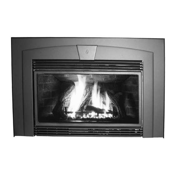
Sienna
B Y : S H E R W O O D I N D U S T R I E S L T D
This appliance is only for use with the type of gas
indicated on the rating plate. This appliance is
not convertible for use with other gases, unless a
certified kit is used.
50-1096
Advertisement
Table of Contents

Related Manuals for Enviro Sienna Indoor Gas Fireplace


Summary of Contents for Enviro Sienna Indoor Gas Fireplace
- Page 1 SHERWOOD INDUSTRIES IS AN ENVIRONMENTALLY RESPONSIBLE COMPANY. THIS MANUAL IS PRINTED ON RECYCLED PAPER. PLEASE KEEP THESE INSTRUCTIONS FOR FUTURE REFERENCE OWNER’S MANUAL WHAT TO DO IF YOU SMELL GAS • Open windows/extinguish any open flame. • Do not try to light any appliance. •...
-
Page 2: Safety Precautions
Safety Precautions FOR SAFE INSTALLATION AND OPERATION OF YOUR “ENVIRO” HEATER, PLEASE CAREFULLY READ THE FOLLOWING INFORMATION: • All ENVIRO gas-fired appliances must be installed in accordance with their instructions. Carefully read all the instructions in this manual first. Consult the building authority having jurisdiction to determine the need for a permit prior to commencing the installation. -
Page 3: Table Of Contents
Table of Contents Safety Precautions...2 Table of Contents...3 Codes And Approvals...4 Specifications...5 Rating Label Location...5 Dimensions...5 Operating Instructions...7 Pilot Lighting Instructions...7 Remote Controls - Optional...7 Burner Lighting...7 Turn Off Unit...8 Blower Speed...8 Normal Sounds During Operation...8 Adjusting Venturi Air Settings...8 Maintenance And Service...9 Cleaning The Glass...9 Cleaning The Firebox...9... -
Page 4: Codes And Approvals
TESTED TO: ANSI Z21.88a-2003/CSA 2.33a-2003 VENTED GAS FIREPLACE HEATERS CAN/CGA 2.17-M91 GAS FIRED APPLIANCES FOR HIGH ALTITUDES CSA P.4.1-02 TESTING METHOD FOR MEASURING ANNUAL FIREPLACE EFFICIENCY This ENVIRO SIENNA Fireplace: • Has been certified for use with either natural or propane gases. (See rating label.) •... -
Page 5: Specifications
ATING ABEL OCATION The rating label is located under the control panel and is attached to a rectangular metal sheet that is chained to the fireplace. IMENSIONS Table 1: Sienna exterior dimensions. (Shaded dimensions shown in Figure 1 & 2.) Surround Style Arched Surround 33”... - Page 6 21" (533 mm) With Trim 46 Without Trim 46" (1168 mm) " (775 mm) Figure 2: Sienna exterior dimensions; example 2. Specifications Sensor Flue (441 mm) " (333 mm) " (1171 mm) " (383 mm) Shown: B-Vent with 33" x 46" (84cm x 193 cm) surround panel with trim "...
-
Page 7: Operating Instructions
Operating Instructions For Your Safety, Read Safety Precautions And Lighting Instructions Before Operating WARNING: IF YOU DO NOT FOLLOW THESE INSTRUCTIONS EXACTLY A FIRE OR EXPLOSION MAY RESULT, CAUSING PROPERTY DAMAGE, PERSONAL INJURY OF LOSS OF LIFE. ILOT IGHTING NSTRUCTIONS Hot while operating. -
Page 8: Turn Off Unit
After the unit has gone through the first burn, turn the unit OFF, including the pilot, and let the unit get completely cold. Then remove the glass and clean it with a good gas fireplace glass cleaner, available at your local Enviro dealer. See “D ” sections. -
Page 9: Maintenance And Service
Do not operate with the glass front removed, cracked or broken. Removal and replacement of the glass from the door must be done by a licensed or qualified service person. The glass must be purchased from an ENVIRO dealer. No substitute materials are allowed. -
Page 10: Glass Door Removal
Maintenance And Service LASS EMOVAL Figure : Top bolts for glass door. & B URNER LOWER EMOVAL 1. Turn the unit off and allow the unit to cool completely. 2. Remove the fascia or louvers, open the door (see M AINTENANCE AND ERVICE ), and remove the log set. -
Page 11: Fuel Conversion
Maintenance And Service ONVERSION TO BE INSTALLED BY A QUALIFIED SERVICE AGENCY ONLY Please read and understand these instructions before installing. Warning: This conversion kit shall be installed by a qualified service agency in accordance with the manufacturer’s instructions and all applicable codes and requirements of the authority having jurisdiction. - Page 12 Maintenance And Service b) Insert a ” or 4 mm Allen wrench into the hexagonal key-way of the screw (see Figure 12), rotate it counter-clockwise until it is free and extract it. Loosen Tighten Figure 12: Removing valve screw. Reinstall the burner, brick panels, log set, embers, and glass door.
-
Page 13: Initial Installation
Initial Installation WARNING: Operation of this heater when not connected to a properly installed and maintained venting system can result in carbon monoxide (CO) poisoning and possible death. LEARANCES TO OMBUSTIBLES Maintain sufficient clearances for operation, service and maintenance. • A clearance of 25 1⁄2” (648 mm) minimum is required from the center of the unit to the sidewalls. •... -
Page 14: Minimum Fireplace Size
Initial Installation WARNING: Operation of this heater when not connected to a properly installed and maintained venting system can result in carbon monoxide (CO) poisoning and possible death. INIMUM IREPLACE Table 3: Minimum dimensions of fireplace for Sienna to be installed into. Description of Fireplace Dimension At Back Width... -
Page 15: Direct Vent Model
Initial Installation QUALIFIED INSTALLERS ONLY IRECT ODEL WARNING: This appliance has been designed to draw room air for proper heat circulation from the sides of the unit. Blocking or modifying the louvers in any way can create hazardous situations. This model is vented with two (2) 3” aluminum or stainless steel flex vent leading into a co-linear to co-axial vent adaptor and using a vertical termination cap. -
Page 16: Venting Fireplace Inserts
IREPLACE NSERTS The ENVIRO SIENNA may be installed and vented into any solid fuel fireplace that has been installed in accordance with the National, Provincial/State and local building codes and has been constructed of non-combustible materials. Before starting refer to I... -
Page 17: Electrical Requirements
Initial Installation QUALIFIED INSTALLERS ONLY LECTRICAL EQUIREMENTS F (49 Temperature Sensor Fan Control CNT4 CNT1 Black Black Black CNT3 CNT2 Green/Yellow White Figure 21: Fan wiring diagram. Optional Remote Control 7 0 ° F Purple Blue BV Only 7 0 ° F F (149 Temperature Sensor... -
Page 18: Gas Line Connection
Initial Installation ONNECTION Warning: Only persons licensed to work with gas piping may make the necessary gas connections to this appliance. Gas Line Connection: •This fireplace is equipped with a certified flexible pipe located on the right side of the unit, terminating in a 3⁄8”... -
Page 19: Converting A Direct Vent Fireplace To A B-Vent Fireplace
Initial Installation QUALIFIED INSTALLERS ONLY ONVERTING IRECT 1. Remove Direct Vent chimney connector assembly by taking out the two (2) T-20 screws at the front of the unit. Push the assembly out from under the brackets at the back and remove (see Figure 24). 2. -
Page 20: Secondary Installation
Secondary Installation NSTALLATION OF URROUND The Sienna must have one of the panels installed around the unit; the unit panel, the filler panel, or the filler panel with trim. If you have trim for your filler panel, the trim must be installed before installing the filler panel onto the unit. -
Page 21: Log Set And Ember Installation
Secondary Installation ET AND MBER NSTALLATION NOTE: The logs are fragile and should be handled gently. The placement of the logs is not arbitrary. If they are positioned incorrectly, the flames can be “pinched” and will not burn correctly. The burner, and a few of the logs come with locator pins, notches and ledges, which make alignment easier. - Page 22 Secondary Installation Figure 33: The front end of the right/center log has a notch in it that is to rest around the right/center post of the grate. The back end of the log rests on the burner tray (see Figure 32). Ensure the log does not block any burn ports.
- Page 23 Secondary Installation Figure 36. Sienna complete log set-up with embers burning. NOTE: While the glass is still removed, it is recommended that the gas line be purged by lighting the pilot. When lighting the fireplace for the first time since the log set and embers have been installed/replaced, watch for ignition at ALL the burner ports.
-
Page 24: Removing The Brick Panel
Secondary Installation EMOVING RICK ANEL The brick panel set is fragile, handle with extreme care. The brick panel set comes pre-installed. The centre and top panel are the only panels that need to be removed if the complete gas and electrical tray assembly must be removed. The side panels may remain installed unless they are to be replaced. -
Page 25: Trouble Shooting
Trouble Shooting Problem Possible Cause The main burner The gas valve may not be on. does not ignite Thermostat is not calling for when called for. heat. Problem with gas valve. Spark will not Defective piezo ignitor. light the pilot after repeatedly Broken spark electrode. -
Page 26: Parts List- Unit Components
Parts List- Unit Components Reference Part Description Number 120°F Ceramic Fan Temperature Sensor 300°F (149°C) Manual Reset Spill Switch (Normally Closed) S.I.T. Nova Valve Convertible Thermocouple Spark Electrode with Ignitor Cable Thermopile Pilot Orifice NG Threaded Pilot Orifice LP Threaded Pilot Gasket S.I.T. -
Page 27: Parts Diagram - Components
Parts Diagram - Components... -
Page 28: Parts Diagram - Burner
Parts Diagram - Burner �� �� �� � � �� � �� � � � � SIENNA - Burner � October 2004... -
Page 29: Parts List - Options
Parts List - Options Reference Option Description Number The Cottage Trim Kit - Gold The Cottage Trim Kit - Pewter The Cottage Trim Kit - Antique Copper The Cottage Trim Kit - Painted Charcoal Cape Cod Doors Unit Panel & Keystone Cottage Filler Panel Louvers (set of 2) -
Page 30: Parts Diagram - Options
Parts Diagram - Options �� �� �� �� �� �� �� SIENNA - Options October 2004... -
Page 31: Installation Data Sheet
Warranty Sherwood Industries Ltd. offers a Limited Lifetime Warranty on this gas product. This Limited Lifetime Warranty covers the appliance for a period of seven years from the date of installation. This warranty applies only to the original owner in the original location. Covered under the lifetime warranty are: the surround, the chassis and the heat exchanger. -
Page 32: Installation Data Sheet
Installation Data Sheet The following information must be recorded by the installer for warranty purposes and future reference. NAME OF OWNER: _________________________________________ ADDRESS: _________________________________________ _________________________________________ _________________________________________ PHONE:___________________________________ MODEL:___________________________________ SERIAL NUMBER:___________________________ DATE OF PURCHASE: _____________ DATE OF INSTALLATION:___________ � DIRECT VENT �...
Need help?
Do you have a question about the Sienna Indoor Gas Fireplace and is the answer not in the manual?
Questions and answers