Table of Contents
Advertisement
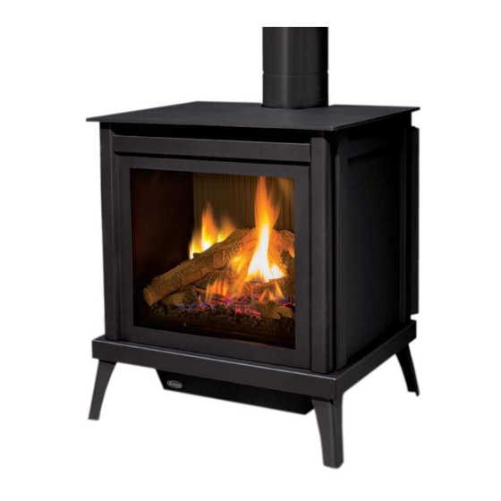
S40
F R E E S T A N D I N G G A S F I R E P L A C E
OWNER'S MANUAL
WARNING:
If the information in this manual is not followed exactly, a
fire or explosion may result causing property damage, personal injury
or loss of life. Installation and service must be performed by a qualified
installer, service agency or the gas supplier.
4001609
50-3258
Version Française: www.enviro.com/fr.html
Advertisement
Table of Contents

Related Manuals for Enviro S40


Summary of Contents for Enviro S40
- Page 1 If the information in this manual is not followed exactly, a fire or explosion may result causing property damage, personal injury or loss of life. Installation and service must be performed by a qualified installer, service agency or the gas supplier. 4001609 50-3258 Version Française: www.enviro.com/fr.html...
-
Page 2: Safety Precautions
Safety Precautions WARNING: FIRE OR EXPLOSION HAZARD Failure to follow safety warnings exactly could result in serious injury, death, or property damage. - Do not store or use gasoline or other flammable vapors and liquids in the vicinity of this or any other appliance. - WHAT TO DO IF YOU SMELL GAS •... - Page 3 NEVER ALLOW CHILDREN shut. TO TOUCH GLASS. • If the S40 unit is pulled out of its installation, and the vent- A barrier designed to reduce the risk of burns from the air intake system is disconnected for any reason, ensure that...
-
Page 4: Table Of Contents
Table of Contents Safety Precautions......................2 Table of Contents......................4 Codes And Approvals....................5 Specifications......................6 Dimensions.....................6 Rating Label Location..................6 Operating Instructions....................7 Lighting Instructions..................7 Pilot Light......................8 Air Shutter......................8 Remote Controls....................8 Burner Lighting....................9 Blower Speed ....................10 Normal Sounds During Operation..............10 Maintenance And Service....................10 Routine Maintenance..................10 Cleaning Decorative Surfaces................10 Cleaning the Glass...................11 Cleaning the Firebox..................11... -
Page 5: Codes And Approvals
After the unit has gone through the first burn, turn the unit off including the pilot, let the unit get cold then remove the glass door and clean it with a good gas fireplace glass cleaner, available at your local ENVIRO dealer. -
Page 6: Specifications
[77 cm] [72.7 cm] 22 7/16" [57 cm] 26 1/8" [66.4 cm] 4 5/8" [11.7 cm] Figure 1. S40 Dimensions & L ating abeL ighting nstRuctions ocation The rating label and lighting instructions are located on a plate hanging on the back of of the unit. -
Page 7: Operating Instructions
Operating Instructions For Your Safety, Read Safety Precautions And Lighting Instructions Before Operating WARNING: IF YOU DO NOT FOLLOW THESE INSTRUCTIONS EXACTLY A FIRE OR EXPLOSION MAY RESULT, CAUSING PROPERTY DAMAGE, PERSONAL INJURY OF LOSS OF LIFE. ighting anD uRning nstRuctions FOR YOUR SAFETY READ BEFORE LIGHTING WARNING... -
Page 8: Pilot Light
Operating Instructions iLot ight 1. Turn off the gas to the fireplace. If not recently done, remove the glass and let the unit air out for at least five (5) minutes to clear out any gas. Turn on gas to the heater. Thermocouple Thermopile 2. -
Page 9: Burner Lighting
Lighting Instructions Before Operating uRneR ighting The S40 gas valve and control panel (Figures 5 & 6) are located behind the valve access door at the front of the stove (Figure 4). To light the burner correctly follow the steps below: Gas Control... -
Page 10: Blower Speed
Operating Instructions LoweR sPeeD The blower will come on only when the fireplace is up to temperature (approximately 15 minutes). The speed of the fan can be changed by turning the fan control knob. The blower will continue to operate automatically after the unit has been shut off (approximately 25 minutes).To turn the blower off, turn the knob COUNTER CLOCKWISE until it “clicks”... -
Page 11: Cleaning The Glass
The glass must be purchased from an ENVIRO dealer. No substitute materials are allowed. Remove the door (see page 12). The replacement glass will come with a new gasket installed. Remove any silicone remnants from the door. -
Page 12: Cabinet Front Removal
Ront emovaL Top Plate The cabinet front on the S40 needs to be removed whenever access to the firebox is required. First the S40 must be turned off and allowed to fully cool. Next, remove the Top Plate as shown in Figure 8 by lifting up and out. -
Page 13: Burner Removal
Maintenance And Service uRneR emovaL The burner may need to be removed for a few reasons, including cleaning under the burner, converting the unit to a different gas type, or to replace the burner altogether. Proceed only when the unit has completely cooled down. -
Page 14: Fuel Conversion
Kit Parts List for all S40 models: 2 - Orifice (NG: #45 & #44) or (LP: 2 x #55 , 1 x #56) - Page 15 Maintenance And Service 7. Convert the SIT gas valve: a) Remove the black protection cap from the HI/LO knob by hand shown in Figure 14. b) Insert a ” or 4 mm Allen wrench into the hexagonal key-way of the screw (see Figure 15), rotate it counter-clockwise until it is free and extract it.
- Page 16 I ntIal ntallatIon . If the S40 has been installed at an altitude higher than 2000ft onnectIon anD estIng (610m) it is required to de-rate the unit accordingly and use the supplied #56 orifice on the left (LP only): In the USA: The appliance may be installed at higher altitudes.
-
Page 17: Initial Installation
• Locate the stove in a large and open room that is centrally located in the house. This will optimize heat circulation and comfort. • As the S40 is equipped with a convection fan, ensure that an electrical outlet is within 6 ft (1.8 m) of the stove. -
Page 18: Direct Vent
The vent length for the S40 must be between 36” (91 cm) and 44ft (13.4 m). This model is vented with co-axial 4” intake, 6 5/8” exhaust aluminum or stainless steel approved rigid vent leading into a vertical or horizontal termination cap. -
Page 19: Approved Venting Parts
4” - 6 5/8” The S40 fireplace has been tested and certified for use with M&G DuraVent DirectVent Pro and ICC EXCELDirect venting systems. Refer to the table below for part numbers of commonly used parts for both venting systems. -
Page 20: Horizontal Termination - Minimum Vent
Refer to the figure for below for the minimum allowable venting setup for the S40. A termination guard (50-3266) is required when the termination is within 7’ (2.13m) of grade. Approved horizontal termination Approved through wall thimble Termination 24”... -
Page 21: Vent Termination Restrictions
Initial Installation QUALIFIED INSTALLERS ONLY eRmination estRictions Fixed Closed Fixed Openable Closed Openable Termination Cap Air Supply Inlet Gas Meter Restriction Zone (Termination not allowed) Figure 23. Vent Termination Restrictions, refer to Table 5. Table 5: Vent termination clearances. Letter Canadian Installation US Installation Description... -
Page 22: Allowable Vent Configurations
Initial Installation QUALIFIED INSTALLERS ONLY LLowabLe onfiguRations Figures 24 show the range of possible vent configurations for vertical and horizontal terminations. Any layout that remains within the shaded areas is acceptable. Having the fewest number of elbows is ideal, as they tend to disrupt air movement. Using 45˚ elbows is preferable to using 90˚ elbows. Also, a shorter vent system will perform better than a longer one. -
Page 23: Air Restrictor Settings
When installing the S40 with 10ft (3.05m) or more of vertical venting it may be necessary to restrict the fresh air supply in the firebox to control the combustion and flame appearance. To install the air restrictor supplied with... -
Page 24: Horizontal Termination
Initial Installation QUALIFIED INSTALLERS ONLY oRizontaL eRmination NOTES: 1. Horizontal pipes must not be level. For every 12 inches (305 mm) of horizontal travel (away from the stove), there should be at least ¼ inch (6.4 mm) of vertical travel. Never allow the vent to run downward, as this could cause high temperatures or even present the possibility of a fire. -
Page 25: Vertical Termination
Initial Installation QUALIFIED INSTALLERS ONLY Step 4. With the hole now framed, the wall thimble installed, and the pipe extending into the wall, proceed to the outside. Attach the termination to the pipe using RTV and Mil-Pac or Rutland No 78 Stove and Gasket Cement to seal joints. - Page 26 Initial Installation QUALIFIED INSTALLERS ONLY STEP 5. Cut hole in the roof centered on the small hole placed in the roof from Step 2. The hole should be of sufficient size to meet minimum requirements for Clearance to Combustibles, as specified. Continue to assemble lengths of pipe and elbows necessary to reach from the ceiling support box up through the roof line.
- Page 27 Initial Installation QUALIFIED INSTALLERS ONLY NOTES: (1) If an offset is necessary in the attic to avoid obstructions, it is important to support the vent pipe every 3 feet (914 mm), to avoid excessive stress on the elbows, and possible separation. Wall straps are available for this purpose (see Figure 30).
-
Page 28: Be-Vent Drafthood Adaptor (50-3229)
RafthooD DaPtoR This Drafthood Adaptor is a complete assembly and is ready to fit onto your S40 in a vertical vent application only. With the Drafthood Adaptor correctly installed and wired to the gas control valve. Your Direct Vent Fireplace can be vented like a B-Vent Fireplace. - Page 29 Initial Installation It is strongly recommended to install an approved chimney liner in an existing brick chimney. This will maximize the potential draft of the chimney and lessen the effects of slow chimney start-up. VENTING OF A FIREPLACE FITTED WITH THE DRAFTHOOD ADAPTOR: Note: Please refer to the chimney manufacturer’s installation instructions prior to commencing the installation.
- Page 30 Initial Installation SPILL SWITCH REPLACEMENT: Use the following instructions to replace the Safety Spill Switch. 1. Turn the unit off and allow it to cool. 2. Disconnect the spill switch wires from the valve and on/off/remote rocker switch wire (see Figure 32). 3.
-
Page 31: Gas Line Connection And Testing
Initial Installation QUALIFIED INSTALLERS ONLY onnection anD esting WARNING: Only persons licensed to work with gas piping may make the necessary gas connections to this appliance. GAS LINE CONNECTION • This stove is equipped with a certified flexible pipe located on the left side of the unit terminating in a 3/8”... -
Page 32: Electrical Requirements
Initial Installation QUALIFIED INSTALLERS ONLY LectRicaL equiRements The fan will not operate if the appliance is cold. Once the unit is lit and the fan is set to the desired level, the fan will automatically turn on upon reaching operating temperature. The fan will automatically turn off after the appliance has cooled down. -
Page 33: Secondary Installation
Secondary Installation nstaLLation The placement of the logs is not arbitrary. If they are positioned incorrectly, the flames can be “pinched” and will not burn correctly. All of the logs come with either a notch or ledge, which make alignment easier. Using the pictures provided, carefully set the logs in place (see Figures 38 through 44). - Page 34 Secondary Installation 5. Install the front three ember bed logs as shown in Figure 41. Note the locating notches on the backside of the logs. The depressions in the ember bed only allow the logs to be installed one way. Figure 41.
- Page 35 A small amount on the bottom side of the logs is normal. Remove and replace the logs in the same manner described above. If new logs are required, contact your nearest ENVIRO dealer. Never operate the fireplace with the glass door removed.
-
Page 36: Safety Screen Replacement
The S40 is supplied with a safety screen already installed on the back of the cast door. If the safety screen becomes damaged must it be replaced with part number 50-3243 following the steps below: Retaining Nuts (x4) Figure 45. -
Page 37: Trouble Shooting
Trouble Shooting Problem Possible Cause Solution The main burner does not The gas valve may not be on. • Check that the gas control knob is in the “ON” position. ignite when called for. Thermostat is not calling for • Adjust the thermostat several degrees above ambient heat. -
Page 38: Parts List
50-3235 Front Door Complete 50-3236 Ceramic Fluted Liner (1 piece) 50-3239 S40 Cabinet Front 50-3240 S40 Plate Top 50-3241 S40 Leg Set (4 pieces) 50-3242 Replacement Safety Screen 50-3243 B Vent Drafthood Adaptor 50-3229 Vent Collar Cover 50-3245 Termination Guard... - Page 39 Parts List...
-
Page 40: Rating Label
Rating Label... -
Page 41: Notes
Notes... - Page 42 Notes...
-
Page 43: Warranty
Exclusions conditions herein set forth, this product against defects in material and workmanship An expanded list of exclusions is available at www.enviro.com/help/warranty.html during the specified warranty period starting from the date of original purchase at retail. This warranty does not cover: In the event of a defect of material or workmanship during the specified warranty period, ƒ... -
Page 44: Installation Data Sheet
� NATURAL GAS (NAT) PROPANE(LPG) _________________________________________ INLET GAS PRESSURE:_________in wc PHONE:___________________________________ MAIN BURNER ORIFICE:__________# DMS PILOT ORIFICE #_________OR________in diam. INSTALLER’S SIGNATURE: _________________________________________ MANUFACTURED BY: SHERWOOD INDUSTRIES LTD. 6782 OLDFIELD RD. SAANICHTON, BC, CANADA V8M 2A3 www.enviro.com December 8, 2016 C-14868...
Need help?
Do you have a question about the S40 and is the answer not in the manual?
Questions and answers