Table of Contents
Advertisement
Quick Links
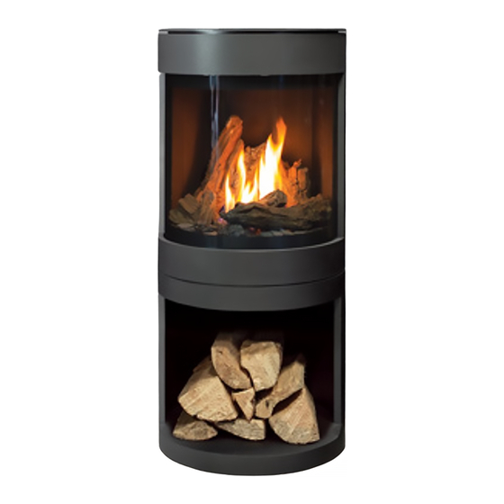
S50I
F R E E S T A N D I N G G A S F I R E P L A C E
OWNER'S MANUAL
WARNING:
If the information in this manual is not followed exactly, a
fire or explosion may result causing property damage, personal injury
or loss of life. Installation and service must be performed by a qualified
installer, service agency or the gas supplier.
C#4001609
CERTIFIED TO/CERTIFIÉ AUX: ANSI Z21.88 / CSA2.33 / CSA 2.17
50-4246
1
Version Française: www.enviro.com/fr.html
Advertisement
Table of Contents

Subscribe to Our Youtube Channel
Related Manuals for Enviro S50I


Summary of Contents for Enviro S50I
- Page 1 Installation and service must be performed by a qualified installer, service agency or the gas supplier. C#4001609 CERTIFIED TO/CERTIFIÉ AUX: ANSI Z21.88 / CSA2.33 / CSA 2.17 50-4246 Version Française: www.enviro.com/fr.html...
-
Page 2: Safety Precautions
Safety Precautions WARNING: FIRE OR EXPLOSION HAZARD Failure to follow safety warnings exactly could result in serious injury, death, or property damage. - Do not store or use gasoline or other flammable vapors and liquids in the vicinity of this or any other appliance. - WHAT TO DO IF YOU SMELL GAS •... - Page 3 NEVER ALLOW CHILDREN shut. TO TOUCH GLASS. • If the S50I unit is pulled out of its installation, and the vent- A barrier designed to reduce the risk of burns from the air intake system is disconnected for any reason, ensure that...
-
Page 4: Table Of Contents
Table of Contents Safety Precautions ���������������������������������������������������������������������������������������������������������������������������2 Table of Contents ������������������������������������������������������������������������������������������������������������������������������4 Codes And Approvals ������������������������������������������������������������������������������������������������������������������������6 Specifications �����������������������������������������������������������������������������������������������������������������������������������7 Dimensions: ............................7 Rating Label & Lighting Instructions Location...................7 Operating Instructions ���������������������������������������������������������������������������������������������������������������������8 Lighting and Turning Off Instructions .......................8 Air Shutter .............................9 Normal Sounds During Operation ......................9 Remote Control Operations ........................9 System Description . - Page 5 Table of Contents Horizontal Termination ......................... 37 Vertical Termination ..........................38 Gas Line Connection ..........................41 Electrical Requirements ........................42 Top Plate Collar Installation ........................43 Rear Vent Conversion ........................... 43 Pedestal Installation ..........................46 Relocating Gas/Electrical ........................48 Mobile Home Installation: ........................
-
Page 6: Codes And Approvals
After the unit has gone through the first burn, turn the unit off including the pilot, let the unit get cold then remove the glass door and clean it with a good gas fireplace glass cleaner, available at your local ENVIRO dealer. -
Page 7: Specifications
Specifications imensions 20" 8 " 18" REAR VENT 16 " POLE PEDESTAL - 40" WOOD PEDESTAL - 40" 3 4 16 " 16 " GAS & 8 " CONTROL POWER PANEL *GAS & POWER CAN 10" RUN UP PEDESTAL Figure 1: S50 Dimensions &... -
Page 8: Operating Instructions
If it is unsuccessful, it will continue operations. If the appliance will not operate, follow the instructions "To Turn Off Gas To Appliance" and call your service technician or gas supplier. C-16303 Figure 3: S50I Lighting Instruction Labels... -
Page 9: Air Shutter
Proflame 2 is a modular remote control system that directs the functions of the S50I. The Proflame 2 TMFSLA is configured to control the on/off main burner operation, its flame levels and provides on/off and Smart thermostatic control of the appliance. The system also controls the fan speed through six (6) levels. -
Page 10: System Description
Operating Instructions ystem escRiption The Proflame 2 Remote Control System consists of two (2) elements: 1. Proflame 2 Transmitter. 2. Integrated Fireplace Controller (IFC) and a wiring harness to connect to the gas valve and stepper motor. ATTENTION! - TURN “OFF” THE MAIN GAS SUPPLY OF THE APPLIANCE DURING INSTALLATION OR MAINTENANCE OF THE IFC�... -
Page 11: Integrated Fireplace Controller (Ifc)
Operating Instructions (ifc): ntegRateD iRepLace ontRoLLeR The Proflame 2 IFC (Figure 7) connects directly to the gas valve, stepper motor, pilot and covection fan with a wiring harness. The IFC is mainly powered by 120 VAC but can also run off a battery backup four (4) AA type batteries for shorter periods of time. -
Page 12: Switching To Continuous Pilot Mode
Operating Instructions Temperature Indication Display With the system in the “OFF” position, press the Thermostat Key and the Mode Key at the same time. Look at the LCD screen on the transmitter to verify that a °C or °F is visible to the right of the Room Temperature display (see Figure 7). - Page 13 Operating Instructions Remote Flame Control The Proflame 2 GTMF has six (6) flame levels. With the system on, and the flame level at the maximum in the appliance, pressing the Down Arrow Key once will reduce the flame height by one step until the flame is turned off.
-
Page 14: Routine Maintenance
Operating Instructions IFC: The life span of the IFC batteries depends on various factors during a prolonged power outage: quality of the batteries used, the number of ignitions of the appliance, the number of changes to the room thermostat set point etc. When the IFC batteries are low, No “beep”... -
Page 15: Maintenance And Service
Maintenance And Service ifting the Late The top plate of the unit is attached to a pair of hinges and tension cable that will support its weight when lifted allowing access for servicing. Lift the top plate upwards until the hinge arms can both be pulled com- pletely outward simultaneously (see Figure 19 and Figure 20 below). -
Page 16: Safety Screen
Maintenance And Service afety cReen The safety screen is attached by two hooks on the top edge of the unit (see Figure 21). Lift top plate to gain safety screen lift clearnace (see instruction previous page); gently and carefully lift the screen up and away from the unit (see Figure 22). -
Page 17: Removing The Door Frame/Skirt
Maintenance And Service The safety screen mounting position can be adjusted slighlty to maining paralellism with the fireplace body lines. The outer standoffs on the lower screen can be repositioned by loosening the two T20 screws and adjusting via slots, retighten screws. emoving the Rame kiRt... -
Page 18: Removing The Glass
Maintenance And Service Pole pedestal Wood pedestal Figure 26: Front Skirt Attachment Figure 27: Front Skirt Hooks emoving the Lass WARNING: No substitute materials or parts can be used. ONLY glass supplied from the manufacturer may be used (replacement part number: 50-4188). Remove the door frame (see previous section for details). -
Page 19: Removing The Rear Chassis
Maintenance And Service emoving the hassis 1. Remove the door frame and skirt (see r eMoVing section on page 17). raMe kirt 2. Remove the venturi knob located on the back of the unit (see Figure 4). It can unscrewed by hand and put aside. -
Page 20: Top Light Replacement
Maintenance And Service ight epLacement Top light replacement bulb: G9 25W 120V (50-4119). Disconnect power cord before proceding. To replace the bulb, first remove the door frame and curved glass (see page 17 andpage 18 for details). Remove top light cover plate (see Figure 33) take care not to damage ceramic fiber gasket, replace if needed. Gently lower the top light assembly and let it hang from the wires. -
Page 21: Replacing Trim Parts
Maintenance And Service Retainer #2 (Attached to unit) Retainer #1 (Removable from unit) Figure 36: Fan Removal (Top-Down View) When replacing the fan, ensure the label-side is facing down and electrical contacts are positioned at the same corner as retainer #1 (see Figure 27). Re-attach the electrical harness and work fan into position by wedg- ing the respective corner into retainer #2 (see Figure 27). - Page 22 Maintenance And Service Figure 38: Front Skirt Removal kiRt Remove the door frame from the unit (refer to the r section on page 17). eMoVing the raMe kirt Next, remove the rear chassis from the unit (refer to the r section of page 19).
-
Page 23: Removing Top Plate
Maintenance And Service emoving Late WARNING: A helper must be used to support the top plate weight while support system is being disconnect- ed� To remove the top plate, first lift the plate and set the support hinges (refer to the “Lifting the Top Plate”... -
Page 24: Fuel Conversion
Maintenance And Service Figure 44: Pilot Fence Removal Figure 43: Burner Platform Removal Figure 45: Burner Removal onveRsion TO BE INSTALLED BY A QUALIFIED SERVICE AGENCY ONLY Please read and understand these instructions before installing. Warning: This conversion kit shall be installed by a qualified service agency in accordance with the manufacturer’s instructions and all applicable codes and requirements of the authority having jurisdiction. - Page 25 Maintenance And Service Kit Parts List for all S50I models: 1 - Orifice (NG: #37) or (LP: #53) 1 - Conversion label 1 - Pilot Orifice (LP orifice supplied with unit) 1 - Installation instruction sheet 1 - Servo Regulator with Diaphram Carefully inspect all parts supplied with this conversion kit.
-
Page 26: Initial Installation
(page 38). Confirm the inlet and manifold pressures are within the acceptable ranges as directed in the g section on page 41. If the S50I has been installed at onnection an altitude higher than 2000ft (610m) it is required to de-rate the unit accordingly: In the USA: The appliance may be installed at higher altitudes. -
Page 27: Clearance To Combustibles
Initial Installation QUALIFIED INSTALLERS ONLY LeaRance to ombustibLes Warning: Clearances must be sufficient to allow for maintenance and service. A. Side Wall to Edge of unit: 12” [30.5 cm] B. Side Wall to Center of unit: 22” [55.9 cm] C. Back Wall to Edge of unit: 3”... -
Page 28: Direct Vent
Figure 51: Vent Framing For Wall or Ceiling. ppRoveD enting aRts The S50I fireplace has been tested and certified for Table 3: Approved Vent Manufacturers use with the venting systems shown in Table 3 & Manufacturer Trade Name Nominal Sizes Table 4. - Page 29 Initial Installation QUALIFIED INSTALLERS ONLY WARNING: Do not mix parts from different vent manufacturers’ systems. EXCEPTION TO WARNING: This product has been evaluated by Intertek for using a DirectVent Pro starting collar in conjunction with other venting systems. Use of this system with the DirectVent Pro starting collar is deemed acceptable and does not affect the Intertek listing of the appliance.
-
Page 30: Vent Termination Restrictions
Initial Installation QUALIFIED INSTALLERS ONLY eRmination estRictions Fixed Closed Fixed Openable Closed Openable Termination Cap Air Supply Inlet Restriction Zone Gas Meter (Termination not allowed) Figure 52: Vent Termination Restrictions, refer to Table 5� Table 5: Vent termination clearances� Letter Canadian Installation US Installation Description... -
Page 31: Exhaust Restrictor Settings
Initial Installation QUALIFIED INSTALLERS ONLY xhaust estRictoR ettings The S50 has an internal exhaust restrictor that can be adjusted externally. Depending on the venting con- figuration this may need to be adjusted. The restrictor dial is accessed from the top of the fireplace, below the top plate (refer to the section “Lifting the Top Plate”... -
Page 32: Minimum Top Vent Configurations
Initial Installation QUALIFIED INSTALLERS ONLY inimum onfiguRations Refer to Table 6 and Figure 54 below for the minimum allowable top venting setup for the S50. Table 6: Minimum Top Vent Configurations “A” [Vertical Rise] “B” [Horizontal Run] Termination Type 12” Max Out Straight Termination 12”... -
Page 33: Top Vent Configuration - Natural Gas (Ng)
Initial Installation QUALIFIED INSTALLERS ONLY (ng) onfiguRation atuRaL NG Top Vent Con gurations 40’ The following charts show the range (12.19m) of venting options available for top vent configurations using either vertical or horizontal terminations in conjunction with 0 - 3 90° elbows in the vertical plane. -
Page 34: Top Vent Configuration - Propane (Lp)
Initial Installation QUALIFIED INSTALLERS ONLY (Lp) onfiguRation Ropane LP Top Vent Con gurations 40’ (12.19m) 30’ (9.14m) 20’ (6.10m) 10’ (3.05m) 2’ (1.22m) 2’ 20’ 10’ 15’ (1.22m) (6.10m) (3.05m) (4.57m) See Minimum Venting Section for Details Figure 56: Top Vent Configuration Diagram - LP... -
Page 35: Minimum Rear Vent Configurations
Initial Installation QUALIFIED INSTALLERS ONLY inimum onfiguRations Refer to Table 7 and Figure 57 below for the minimum allowable rear venting setup for the S50. Table 7: Minimum Rear Vent Configurations “A” [Horizontal Run] Termination Type 18” [Max] 14” Snorkel up to 36”... -
Page 36: Rear Vent - Corner Installation
Initial Installation QUALIFIED INSTALLERS ONLY oRneR nstaLLation ATTENTION When performing an LP Rear Vent Corner Install with 45° Elbow, a DURAVENT 36” SNORKEL MUST BE USED. No other brand venting can be used for LP corner installations. Rear vent corner installs have the same vent run restrictions as a typical rear vent installations. Refer to Table 7 in the previous section for details. -
Page 37: Horizontal Termination
Initial Installation QUALIFIED INSTALLERS ONLY oRizontaL eRmination NOTES: 1. Horizontal pipes must not be level. For every 12 inches (305 mm) of horizontal travel (away from the stove), there should be at least ¼ inch (6.4 mm) of vertical travel. Never allow the vent to run downward, as this could cause high temperatures or even present the possibility of a fire. -
Page 38: Vertical Termination
Initial Installation QUALIFIED INSTALLERS ONLY Step 4. With the hole now framed, the wall thimble installed, and the pipe extending into the wall, proceed to the outside. Attach the termination to the pipe using RTV and Mil-Pac or Rutland No 78 Stove and Gasket Cement to seal joints. - Page 39 Initial Installation QUALIFIED INSTALLERS ONLY STEP 5� Cut hole in the roof centered on the small hole placed in the roof from Step 2. The hole should be of sufficient size to meet minimum requirements for Clearance to Combustibles, as specified. Continue to assemble lengths of pipe and elbows necessary to reach from the ceiling support box up through the roof line.
- Page 40 Initial Installation QUALIFIED INSTALLERS ONLY NOTES: (1) If an offset is necessary in the attic to avoid obstructions, it is important to support the vent pipe every 3 feet (914 mm), to avoid excessive stress on the elbows, and possible separation. Wall straps are available for this purpose (see Figure 62).
-
Page 41: Gas Line Connection
Initial Installation QUALIFIED INSTALLERS ONLY onnection WARNING: Only persons licensed to work with gas piping may make the necessary gas connections to this appliance. onnection This stove is equipped with a certified flexible pipe located on the left side of the unit terminating in a 3/8” female NPT fitting. -
Page 42: Electrical Requirements
Ventilateur (Optionnel) FUSE 2A/ TOP LIGHT/ Fusible 2A Lumiére Supérieure POWER/ Électrique FUSE 2A/ Fusible 2A VALVE / Vanne IFC CONTROL BOARD /Contrôleur IFC PILOT/ Veilleuse IFC RESET/ Réinitialiser IFC BURNER SWITCH/ Interrupteur Du Brûleur Figure 66: S50I Wiring Diagram... -
Page 43: Top Plate Collar Installation
Initial Installation QUALIFIED INSTALLERS ONLY Late oLLaR nstaLLation The top plate collar is an aesthetic band that helps hide the venting connection for top vent applications. Prior to installing the venting, place the collar on top of the unit around the vent adaptor (see Figure 67). The collar does not fasten to the unit but is heavy enough to sit in place securely. - Page 44 Initial Installation QUALIFIED INSTALLERS ONLY Figure 69: Restrictor Rod Removal Figure 70: Vent Adapter Removal 8. Remove the exhaust spigot from the top of the unit by removing the four (4) T20 screws (see Figure 71). Be deli- cate with the gasket, you will be reusing this. 9.
- Page 45 Initial Installation QUALIFIED INSTALLERS ONLY 10. Attach the exhaust spigot to where the block-off plate was removed (see Figure 73). 11. Attach the vent adapter over top of the exhaust spigot (see Figure 74). 12. Remove the punchout from the rear chassis using a size- able hammer (see Figure 75).
-
Page 46: Pedestal Installation
Initial Installation QUALIFIED INSTALLERS ONLY eDestaL nstaLLation The pedestal MUST be anchored to the floor. *Note: If planning to reroute the electrical and gas connections through the pedestal, complete the steps in section R eLocating LectRicaL on page 48 before proceding. The pedestal comes packaged with rigid foam to help secure and cushion it during transportation. - Page 47 Initial Installation QUALIFIED INSTALLERS ONLY The pole pedestal comes with an anchor Front of Unit plate to help secure it to the floor (see Figure 81 for geometry and orientation). To install: • Mark desired center location for the unit on the floor and align with crosshair on the anchor.
-
Page 48: Relocating Gas/Electrical
Initial Installation QUALIFIED INSTALLERS ONLY eLocating LectRicaL By default, the electrical and gas connections are found at the back of the unit. There is an option to reroute the gas and electrical connections through the pedestal for a more concealed look. The conversion must be done before pedestal installa- tion. - Page 49 Initial Installation QUALIFIED INSTALLERS ONLY eLocating onnection 1. Disconnect the two (2) T20 screws securing the ball valve plate (see Figure 88). 2. Disconnect the four (4) T20 screws securing the ball valve. 3. Loosen off ball valve jam screw and reattach ball valve cradle onto the relocation plate (included in the manual bag, refer to Figure 90 for proper geometry and orien- tation).
- Page 50 Initial Installation QUALIFIED INSTALLERS ONLY eRouting LectRicaL onnections eDestaL The electrical and gas line conduit can run stright up the pole from the floor below. Alternatively you could run them through the channel at the rear of the pedestal base (see Figure 87). Figure 93: Pole Pedestal Gas &...
-
Page 51: Mobile Home Installation
Initial Installation QUALIFIED INSTALLERS ONLY Figure 96: Wood Pedestal Gas & Electrical Rerouting obiLe nstaLLation All S50 models can be installed in a mobile home and must be securely fastened to the floor as directed below: Pedestal Anchor (Required) Flooring Steel Frame ”... -
Page 52: Secondary Installation
Secondary Installation nstaLLation Prior to setting up the log set, remove the door frame and glass from the unit. Refer to their respective sections on page 17 and page 18 for detailed instructions. STEP 1: Place burner media on burner. Use either vermiculite or ember wool;... - Page 53 Secondary Installation STEP 6: Place Log 6 atop the flat surface of Log 5; the base should contact the firebox edge. See Figure 102. Figure 102: Step 6 - Log 6 STEP 7: Place the narrow notch underneath Log 7 into the groove on Log 4.
-
Page 54: Media Installation
Secondary Installation Figure 106: Proper Log Setup/Burn eDia nstaLLation To install media into your unit, perform the following steps: 1. Remove the door frame (refer to section r on page 17). eMoVing the raMe kirt 2. Remove the glass (refer to section r on page 18). -
Page 55: Trouble Shooting
Trouble Shooting... - Page 56 Trouble Shooting...
-
Page 57: Parts List
S50 Traditional Log Set 50-4069 S50 Birch Log Set 50-4070 S50 Diamond Glass Media 50-4071 2A Glass Fuse 50-2075 S50 IPI Circulation Fan Kit - 70 CFM 50-4247 S50I Owner’s Manual 50-4246 12 oz. Can of Metallic Black Touch Up Paint PAINT-12-MB... - Page 58 Parts List Figure 108: Parts List Diagram...
- Page 59 Sherwood Industries Ltd. (“Sherwood”) hereby warrants, subject to the terms and conditions herein set forth, this product against defects in material and workmanship An expanded list of exclusions is available at www.enviro.com/help/warranty.html during the specified warranty period starting from the date of original purchase at retail.
-
Page 60: Installation Data Sheet
_________________________________________ _________________________________________ NATURAL GAS (NAT) PROPANE(LPG) _________________________________________ INLET GAS PRESSURE:_________in wc PHONE:___________________________________ MAIN BURNER ORIFICE:__________# DMS PILOT ORIFICE #_________OR________in diam. INSTALLER’S SIGNATURE: _________________________________________ MANUFACTURED BY: SHERWOOD INDUSTRIES LTD. 6782 OLDFIELD RD. SAANICHTON, BC, CANADA V8M 2A3 www.enviro.com Winter 2022 C-16447...
Need help?
Do you have a question about the S50I and is the answer not in the manual?
Questions and answers