Table of Contents
Advertisement
Quick Links
One Technology Way • P.O. Box 9106 • Norwood, MA 02062-9106, U.S.A. • Tel: 781.329.4700 • Fax: 781.461.3113 • www.analog.com
Evaluating the
FEATURES
Self-contained board, including synthesizer, 100 MHz
reference, USB interface, and voltage regulators
Accompanying software allows control of synthesizer
functions from a PC (via USB interface)
Externally powered by 5.5 V and 15 V supplies
EVALUATION KIT CONTENTS
EV-ADF4159EB1Z or EV-ADF4159EB3Z evaluation board
CD with evaluation software
USB cable
REQUIRED ADDITIONAL EQUIPMENT
VCO (for EV-ADF4159EB3Z)
Loop filter components (for EV-ADF4159EB3Z)
Soldering equipment
Spectrum analyzer
Power supplies (5.5 V and 15 V)
Windows®-based PC with USB port for evaluation software
REQUIRED DOCUMENTS
ADF4159
data sheet
UG-383
user guide
PLEASE SEE THE LAST PAGE FOR AN IMPORTANT
WARNING AND LEGAL TERMS AND CONDITIONS.
ADF4159
Frequency Synthesizer for Phase-Locked Loops
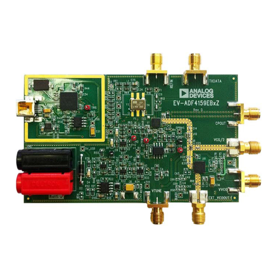
EVALUATION BOARD PHOTOGRAPH
Rev. A | Page 1 of 16
Evaluation Board User Guide
REQUIRED SOFTWARE
Analog Devices ADF4158-9 evaluation software, Version 4.x
or higher (included on the CD in the evaluation board kit or
available for download at www.analog.com)
GENERAL DESCRIPTION
The EV-ADF4159EB1Z/ EV-ADF4159EB3Z evaluates the
performance of the
ADF4159
locked loops (PLL). A photograph of the evaluation board is
shown in Figure 1. The evaluation board involves the
synthesizer, a USB connector, SMA connectors, a reference
oscillator, and power supply connectors. There are also footprints
for active filter components and a voltage controlled oscillator
(VCO); if used, these components must be soldered to the board
to complete the loop. An on-board temperature compensated
crystal oscillator (TCXO) provides the 100 MHz reference
frequency, and a USB cable is included to connect the board to
a PC USB port.
In addition, the evaluation kit contains Windows-based software
to allow easy programming of the synthesizer.
Figure 1.
UG-383
frequency synthesizer for phase-
ADF4159
Advertisement
Table of Contents

Subscribe to Our Youtube Channel
Related Manuals for Analog Devices EV-ADF4159EB1Z


Summary of Contents for Analog Devices EV-ADF4159EB1Z
-
Page 1: Features
FEATURES REQUIRED SOFTWARE Self-contained board, including synthesizer, 100 MHz Analog Devices ADF4158-9 evaluation software, Version 4.x reference, USB interface, and voltage regulators or higher (included on the CD in the evaluation board kit or Accompanying software allows control of synthesizer available for download at www.analog.com) -
Page 2: Table Of Contents
Evaluation Kit Contents ..............1 Loop Filter ..................4 Required Additional Equipment ............ 1 VCO Configuration ................5 Required Documents ............... 1 EV-ADF4159EB1Z ................5 Required Software ................1 EV-ADF4159EB3Z ................5 General Description ................. 1 Evaluation Setup ................6 Evaluation Board Photograph ............1 Getting Started ...................7... -
Page 3: Evaluation Board Hardware
Connect the The VCO configuration is different for each evaluation board red connector to a 5.5 V power supply and the black connector model: EV-ADF4159EB1Z and EV-ADF4159EB3Z. See the to ground. VCO Configuration section for more information. -
Page 4: Loop Filter
UG-383 Evaluation Board User Guide LOOP FILTER Sample Loop Filter Use the parameters of the sample loop filter described in this The loop filter schematic is included in Figure 13. The general section as a guide for adding a loop filter onto the evaluation placement of loop filter components is shown in Figure 3. -
Page 5: Vco Configuration
EV-ADF4159EB1Z The EV-ADF4159EB3Z evaluation board does not have a VCO The EV-ADF4159EB1Z evaluation board has a MACOM VCO installed. The board is configured for use with an external VCO (MAOC-009269) with a range of 11.4 GHz to 12.8 GHz installed. -
Page 6: Evaluation Setup
UG-383 Evaluation Board User Guide EVALUATION SETUP REFERENCE CRYSTAL TO PC ADF4159 50Ω TERMINATION OP AMP 5.5V TO SPECTRUM ANALYZER Figure 4. Evaluation Setup Block Diagram Figure 5. Evaluation Setup Rev. A | Page 6 of 16... -
Page 7: Getting Started
Click Write All Registers (7, 6, 6, 5, 5, 4, 4, 3, 2, 1, 0) or guide. The control software for the EV-ADF4159EB1Z and EV- manually write to each register (Write R7, Write R6 - Ramp 1, ADF4159EB3Z is provided on the CD included in the evaluation Write R6 - Ramp 2, Write R5 - Ramp 1, Write R5 - Ramp 2, board kit. -
Page 8: Using The Software-Main Controls
UG-383 Evaluation Board User Guide USING THE SOFTWARE—MAIN CONTROLS Phase Detector Polarity to negative when using an inverting active loop filter configuration (as is on this evaluation board). Use the Main Controls tab to select the RL and PLL settings. The Muxout drop-down box allows you to choose the signal Because the evaluation board is set up to feedback the VCO/2 that is connected to the output of the MUXOUT pin. -
Page 9: Using The Software-Ramp And Shift-Key Controls
Evaluation Board User Guide UG-383 USING THE SOFTWARE—RAMP AND SHIFT-KEY over 50 MHz with an up ramp time of 96 µs. (Up ramp refers to the ramp from the initial frequency to the end frequency, CONTROLS whereas down ramp refers to the ramp/jump from the end In the Ramps and Shift-keying tab, you can configure the frequency back to the initial frequency.) For 50 MHz, the PLL is ramping and shift-keying functionality of the ADF4159. - Page 10 UG-383 Evaluation Board User Guide Figure 9. Software—Ramp Controls Rev. A | Page 10 of 16...
-
Page 11: Evaluation Board Schematics
Evaluation Board User Guide UG-383 EVALUATION BOARD SCHEMATICS Figure 10. Evaluation Board Schematic (Page 1) Rev. A | Page 11 of 16... - Page 12 UG-383 Evaluation Board User Guide Figure 11. Evaluation Board Schematic (Page 2) Rev. A | Page 12 of 16...
- Page 13 Evaluation Board User Guide UG-383 Figure 12. Evaluation Board Schematic (Page 3) Rev. A | Page 13 of 16...
- Page 14 UG-383 Evaluation Board User Guide Figure 13. Evaluation Board Schematic (Page 4) Rev. A | Page 14 of 16...
- Page 15 Evaluation Board User Guide UG-383 NOTES Rev. A | Page 15 of 16...
- Page 16 By using the evaluation board discussed herein (together with any tools, components documentation or support materials, the “Evaluation Board”), you are agreeing to be bound by the terms and conditions set forth below (“Agreement”) unless you have purchased the Evaluation Board, in which case the Analog Devices Standard Terms and Conditions of Sale shall govern. Do not use the Evaluation Board until you have read and agreed to the Agreement.
Need help?
Do you have a question about the EV-ADF4159EB1Z and is the answer not in the manual?
Questions and answers