Table of Contents
Advertisement
Quick Links
One Technology Way • P.O. Box 9106 • Norwood, MA 02062-9106, U.S.A. • Tel: 781.329.4700 • Fax: 781.461.3113 • www.analog.com
Evaluation Board for Fractional-N/Integer-N PLL Frequency Synthesizer
FEATURES
Self-contained board including PLL, VCO, loop filter (3 kHz),
USB interface, and voltage regulators
Accompanying software allows control of synthesizer
functions from a PC
Choice of power supply via USB or external feeding
Typical phase noise performance of −111 dBc/Hz @ 100 kHz
offset from carrier (6.8 GHz output frequency)
GENERAL DESCRIPTION
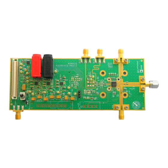
The EV-ADF5355SD1Z is designed to evaluate the performance
of the ADF5355 frequency synthesizer. A digital picture of the
board is shown in Figure 1. It contains the ADF5355
PLEASE SEE THE LAST PAGE FOR AN IMPORTANT
WARNING AND LEGAL TERMS AND CONDITIONS.
DIGITAL PICTURE OF EVALUATION BOARD
Figure 1.
Rev. Pr C | Page 1 of 17
Evaluation Board User Guide
synthesizer, a USB connector and related interface, SMA
connectors for the RF outputs, and reference signal plus headers
for various signals and voltages. There is also a loop filter
(5 kHz) on board. An SDP-S connector is required to operate
the board, this is ordered separately.
The package also contains Windows® software (XP, Vista-and
Windows 7 compatible) to allow easy programming of the
synthesizer.
EVALUATION KIT CONTENTS
Evaluation board software CD
USB cable
EV-ADF5355SD1Z
UG-
Advertisement
Table of Contents

Related Manuals for Analog Devices EV-ADF5355SD1Z


Summary of Contents for Analog Devices EV-ADF5355SD1Z
-
Page 1: Features
(6.8 GHz output frequency) synthesizer. GENERAL DESCRIPTION EVALUATION KIT CONTENTS The EV-ADF5355SD1Z is designed to evaluate the performance Evaluation board software CD of the ADF5355 frequency synthesizer. A digital picture of the USB cable board is shown in Figure 1. It contains the ADF5355... -
Page 2: Table Of Contents
Evaluation Board User Guide TABLE OF CONTENTS Features ....................1 Power Supplies ................3 General Description ................. 1 RF Output ..................3 Evaluation Kit Contents ..............1 Loop Filter ..................3 Digital Picture of Evaluation Board ..........1 Reference Source ................3 ... -
Page 3: Evaluation Board Hardware
Figure 2. Loop Filter Placement RF OUTPUT REFERENCE SOURCE The EV-ADF5355SD1Z has one pair of SMA output connectors The evaluation board contains a footprint for a 122.88 MHz differential output TCXO from Vectron. If preferred, the user (differential outputs RFoutA+/-). The device is quite sensitive to impedance unbalance. -
Page 4: Evaluation Set Up
Evaluation Board User Guide EVALUATION SET UP 50 Ohm 50 Ohm Termination Termination Lock detect LED Loop filter ADF5355 Spectrum Analyzer power Reference In/Out Reference (optional) Power switch TCXO Figure 3. Evaluation Set Up Rev. Pr C | Page 4 of 17... -
Page 5: Evaluation Board Software
Windows XP Software Installation Guide SOFTWARE INSTALLATION Use the following steps to install the software. Install the Analog Devices ADF4355 software by double- clicking ADF4355 Setup.msi. If you are using Windows XP, follow the instructions in the Windows XP Software Installation Guide section (see Figure 4 to Figure 8). - Page 6 Evaluation Board User Guide Click Close. Windows Vista and Windows 7 Software Installation Guide Figure 6. Windows XP ADF4355 Software Installation, Confirm Installation Click Next. Figure 9. Windows Vista/7 ADF4355 Software Installation, Setup Wizard Click Next. Figure 7. Windows XP ADF4355 Software Installation, Logo Testing Click Continue Anyway.
- Page 7 Click Install. Figure 15. Windows XP USB Driver Installation, Install Options Click Next. Note that Figure 15 may list Analog Devices RFG.L Eval Board instead of ADF4xxx USB Adapter Board. Figure 13. Windows Vista/7 ADF4355 Software Installation, Install Complete Click Close.
- Page 8 Evaluation Board User Guide Figure 16. Windows XP USB Driver Installation, Logo Testing Click Continue Anyway. Figure 17. Windows XP USB Driver Installation, Complete Installation Click Finish. Rev. Pr C | Page 8 of 17...
- Page 9 PC, and the SDP board to the evaluation board and ADF5355 as the part. Connect 6.0V to the EV-ADF5355SD1Z board, but then click the ADF4355 file on the desktop or in the Start ensure the switch s1 is in the off position.
- Page 10 Evaluation Board User Guide To adjust the synthesizer parameters click the main controls tab. Default settings are recommended for most registers. Changing the settings on the software GUI requires the user to update the Use the Frequency text box in the Reference section to set the register with the register button, which is highlighted in green.
- Page 11 Evaluation Board User Guide R&S FSUP 26 Signal Source Analyzer LOCKING Settings Residual Noise [T1 w/o spurs] Phase Detector +0 dB Signal Frequency: 6.800000 GHz Int P HN (1.0 k .. 30.0 M) -38.9 dBc Signal Level: -0.28 dBm Residual P M 0.923 °...
-
Page 12: Evaluation Board Schematics And Artwork
Evaluation Board User Guide EVALUATION BOARD SCHEMATICS AND ARTWORK Figure 20. Evaluation Board Schematic (Page 1) Rev. Pr C | Page 12 of 17... - Page 13 Evaluation Board User Guide Figure 21. Evaluation Board Schematic (Page 2) Rev. Pr C | Page 13 of 17...
- Page 14 Evaluation Board User Guide Figure 22. Evaluation Board Schematic (Page 3) Rev. Pr C | Page 14 of 17...
- Page 15 Evaluation Board User Guide Figure 23. Evaluation Board Silk Screen(Top Side) Rev. Pr C | Page 15 of 17...
- Page 16 Evaluation Board User Guide Figure 24 Evaluation Board Silk Screen, (Reverse side) Rev. Pr C | Page 16 of 17...
- Page 17 Legal Terms and Conditions By using the evaluation board discussed herein (together with any tools, components documentation or support materials, the “Evaluation Board”), you are agreeing to be bound by the terms and conditions set forth below (“Agreement”) unless you have purchased the Evaluation Board, in which case the Analog Devices Standard Terms and Conditions of Sale shall govern. Do not use the Evaluation Board until you have read and agreed to the Agreement.
Need help?
Do you have a question about the EV-ADF5355SD1Z and is the answer not in the manual?
Questions and answers