GW Instek AFG-3000 Series User Manual And Text Book
Rf & communication trainer
Hide thumbs
Also See for AFG-3000 Series:
- Manual (299 pages) ,
- Programming manual (119 pages) ,
- Quick start manual (30 pages)

Related Manuals for GW Instek AFG-3000 Series


Summary of Contents for GW Instek AFG-3000 Series
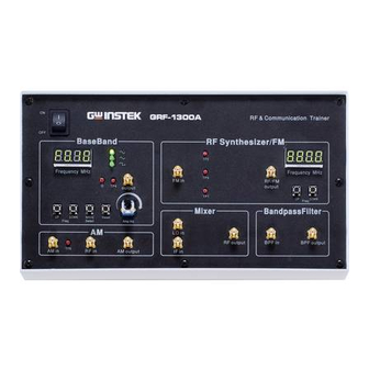
- Page 1 RF & Communication Trainer GRF-1300A STUDENT BOOK USER MANUAL and TEXT BOOK GW INSTEK PART NO. 82RF-1300AM01 ISO-9001 CERTIFIED MANUFACTURER...
- Page 2 This manual contains proprietary information, which is protected by copyright. All rights are reserved. No part of this manual may be photocopied, reproduced or translated to another language without prior written consent of Good Will Corporation. The information in this manual was correct at the time of printing. However, Good Will continues to improve its products and therefore reserves the right to change the specifications, equipment, and maintenance procedures at any time without notice.
-
Page 3: Table Of Contents
Table of Contents able of Contents SAFETY INSTRUCTIONS ..............2 ABOUT THIS BOOK ............... 5 INTRODUCTION to the GRF-1300A ..........6 Package Contents ....................8 Product Specifications and Function................ 8 Usage Instructions ....................9 OVERVIEW of the TIME and FREQUENCY DOMAIN ....16 Observation from a different perspective ..............16 AN INTRODUCTION to SPECTRUM ANALYZERS ...... -
Page 4: Safety Instructions
GRF-1300A User Manual and Teaching Materials AFETY INSTRUCTIONS This chapter contains important safety instructions that should be followed when operating and storing the GRF-1300A. Read the following before any operation to ensure your safety and to keep the GRF-1300A in the best condition. Safety Symbols These safety symbols may appear in this manual or on the instrument. - Page 5 Safety Instructions (Measurement categories) EN 61010-1:2010 specifies the measurement categories and their requirements as follows. The device falls under category I. • Measurement category IV is for measurement performed at the source of a low-voltage installation. • Measurement category III is for measurement performed in a building installation. •...
- Page 6 GRF-1300A User Manual and Teaching Materials Disposal Do not dispose this device as unsorted municipal waste. Please use a separate collection facility or contact the supplier from which this instrument was purchased. Please make sure discarded electrical waste is properly recycled to reduce environmental impact. Power cord for the United Kingdom When using the device in the United Kingdom, make sure the power cord meets the following safety instructions.
-
Page 7: About This Book
Introduction to the GRF-1300A BOUT THIS BOOK This textbook was developed in conjunction with the GRF- 1300A RF & Communication Trainer and the GSP-730 3GHz spectrum analyzer as an RF communications education system. It not only offers detailed examples, but also the practical knowledge necessary for RF measurements, such as spectrum analyzer principals, as well as AM and FM communication systems. -
Page 8: Introduction To The Grf-1300A
GRF-1300A User Manual and Teaching Materials NTRODUCTION to the GRF-1300A The GRF-1300A is a well designed training kit capable of producing a 3MHz baseband signal and a carrier signal up to 900MHz. The GRF-1300A is also able to perform AM and FM RF circuit experiments as well. - Page 9 Introduction to the GRF-1300A functions. This allows students to see in detail how the theory relates to the practical aspects of the RF circuitry. This system is a collection of different functions: signal generation, frequency modulation, amplitude modulation, communication and other functions. Connecting different modules together can create a number of different RF circuit experiments.
-
Page 10: Package Contents
GRF-1300A User Manual and Teaching Materials Package Contents This package contains the GRF-1300A unit, RF cable – 3 * 10cm, 1*20cm,RF cable 2* 80cm, a user manual CD, a student book, an antenna, a power cord and so on. Title Photo Note GRF-1300A... -
Page 11: Usage Instructions
Introduction to the GRF-1300A ≥-35dBm LO-IF ≥-60dBm Mixer+modulation Frequency Centre: Bandwidth:±20MHz Bandpass Filter 2.4GHz Turn circuits on or off by remote command for Communication the diagnostic experiments. Usage Instructions Procedure 1. For safety purposes, please connect the unit to the correct AC power source: 100V~240V, 50-60Hz. - Page 12 GRF-1300A User Manual and Teaching Materials used to adjust the frequency of the baseband signal. The baseband module is adjustable in 10kHz steps. • WAVE Select is used to select three different baseband waveforms. When the waveform is selected, the corresponding LED light will be lit up.
- Page 13 Introduction to the GRF-1300A • The Four-digit display is used to display the frequency of the carrier signal. • FM in port and RF / FM Output port are used to receive the FM signal and output the carrier signal respectively. •...
- Page 14 GRF-1300A User Manual and Teaching Materials 7. There are five test points (Tp1, Tp2, Tp3, Tp4, Tp5) on the panel. These five test points are set at different points in the circuit path of the connected modules. Their specific locations are as shown in the Figure below.
- Page 15 Introduction to the GRF-1300A Figure A-8. Software installation • Next, click on the “Continue Anyway” button to continue the installation until the installation procedure is complete. Figure A-9. Installation procedure is complete • After the software installation is complete, users can perform a system error check by sending commands to the GRF-1300A using Hyper Terminal.
- Page 16 GRF-1300A User Manual and Teaching Materials Figure A-10. Operation interface for HyperTerminal...
- Page 17 Introduction to the GRF-1300A 9. Below is a table listing each instruction and a description of each function. Instruction Function *IDN? Returns the manufacturer, model name and serial number. Returns the value on the digital display of the FM/RF module. Returns the value on the digital display on baseband module.
-
Page 18: Overview Of The Time And Frequency Domain
GRF-1300A User Manual and Teaching Materials VERVIEW of the TIME and FREQUENCY DOMAIN Observation from a different perspective When a signal is said to be in the time domain, it means that the signal is expressed as a function of time. For example, if we describe a sine wave signal that repeats once each microsecond (μsec, 10 ), it means that the period of the signal is 1... - Page 19 Overview of the Time and Frequency Domain from an oscilloscope and power (dBm) from a spectrum analyzer. Voltage and power can be converted from one to the other, so both of them can be used to display the strength of a signal.
- Page 20 GRF-1300A User Manual and Teaching Materials Time domain Frequency domain...
- Page 21 Overview of the Time and Frequency Domain NOTES...
- Page 22 GRF-1300A User Manual and Teaching Materials NOTES...
- Page 23 Overview of the Time and Frequency Domain NOTES...
- Page 24 GRF-1300A User Manual and Teaching Materials NOTES...
- Page 25 Overview of the Time and Frequency Domain NOTES...
-
Page 26: An Introduction To Spectrum Analyzers
GRF-1300A User Manual and Teaching Materials N INTRODUCTION to SPECTRUM ANALYZERS Spectrum analyzers are one of the most important instruments for RF microwave measurements. Being familiar with spectrum analyzers in general is very important for operating high frequency microwave equipment or for performing communication measurements. -
Page 27: Attenuator
An Introduction to Spectrum Analyzers Figure B-1. The basic structure of a Mixers Detection broadband RF Input receiver & Display BPFs Unit Tunable LOs Next, we are going to introduce the other basic functional blocks that a spectrum analyzer is composed of. These blocks are often mentioned when instructed on how to use a spectrum analyzer. - Page 28 GRF-1300A User Manual and Teaching Materials Figure B-3. Mixers Basic structure of RF Input Detection a resolution & Display bandwidth filter Unit BPFs Filter Attenuators Tunable LOs Figure B-4 shows how two different RBW filters distinguish between two signals that are close to each other in frequency. The bandwidth of RBW2 is wider that of RBW1.
-
Page 29: Detector
An Introduction to Spectrum Analyzers Signal under test Figure B-5. The effect of different RBWs Results RBW1 RBW2 Detector Following the RBW filter, the detector detects the power and coverts it to DC voltage via an ADC so that it can be displayed. - Page 30 GRF-1300A User Manual and Teaching Materials Figure B-8 shows how the VBW affects the displayed output. If the signal under test passes through two different VBW filters, in which VBW1 is less than VBW2, we can see that the magnitude of the noise floor of VBW2 is greater than that in VBW1.
- Page 31 An Introduction to Spectrum Analyzers NOTES...
- Page 32 GRF-1300A User Manual and Teaching Materials NOTES...
-
Page 33: Rf Communication And Signals Experiments
In this chapter we will explain the basic operating principals of a spectrum analyzer and introduce the measurement experiments. Prior to this, we will briefly explain how to operate the GW Instek GSP-730 spectrum analyzer. For more detail about its operation, please refer to the GSP-730 user manual. -
Page 34: Experiment 1: Basic Operation Of A Spectrum Analyzer
GRF-1300A User Manual and Teaching Materials Experiment 1: Basic Operation of a Spectrum Analyzer Relevant In addition to the sky, oceans and forests, there is an information invisible, intangible, inaudible and complex electromagnetic network in our living environment. This network is intertwined with wireless signals of various frequency bands. - Page 35 RF Communication and Signals Experiments The figure above is a screen shot from a typical spectrum analyzer display. The horizontal setting is frequency and the vertical axis is amplitude. Therefore a spectrum analyzer is basically used to perform frequency and amplitude-related measurements.
- Page 36 GRF-1300A User Manual and Teaching Materials Step3 Step4 Now we should see some signals on the spectrum analyzer screen. Identify the three highest peaks and write down their frequency values. The reference level can be used to adjust the strength of the signal. As mobile phones use frequency hopping, we can use the Peak Hold function to hold the reading of the signal on the display screen.
- Page 37 RF Communication and Signals Experiments Frequency: _____Amplitude:_____ Frequency: _____Amplitude:_____ Table 1-1. Frequency and amplitude of mobile phone’s transmitter signal. Question In addition to the mobile phone signal, what other wireless signals can be measured in the environment?
-
Page 38: Experiment 2: Measuring A Baseband Waveform
GRF-1300A User Manual and Teaching Materials Experiment 2: Measuring a Baseband Waveform Relevant Relative to oscilloscopes, spectrum analyzers have many information outstanding advantages. They are also the primary measurement tool for measuring frequency domain data. Learning how to use a spectrum analyzer is an essential skill that every student must master to gain RF knowledge. - Page 39 RF Communication and Signals Experiments Step2 Step3 Connect the baseband signal from the output port of the GRF- 1300A to the input terminal of the GSP-730 using the RF wire. Set the GSP-730 as follows: • Center frequency: 2.5MHz • Start frequency: 0kHz, •...
- Page 40 GRF-1300A User Manual and Teaching Materials After step 6 is done, make sure the "Delta" marker is used for the next steps and not the "Normal" marker. Set the Delta Marker to the peak point of each harmonic and make a record by drawing a simple sketch of the spectrum in table 2-1.
- Page 41 RF Communication and Signals Experiments The 2 harmonic ratio is: The 3 harmonic ratio is: Table 2-1. 1MHz sine wave spectrum test results Question 1. What is the spectrum of a theoretical sine wave and why is it different with the actual measured one? 2.
-
Page 42: Experiment 3: Different Baseband Waveforms And Their Harmonic Measurement
GRF-1300A User Manual and Teaching Materials Experiment 3: Different Baseband Waveforms and their Harmonic Measurement Relevant You should already be familiar with electrical signals in information general. We have already said that an oscilloscope is used to observe the amplitude of a waveform. In other words, it is used to observe how an electrical signal, X(t), varies over time. - Page 43 RF Communication and Signals Experiments Experiment Set the waveform on the GRF-1300A and measure the principles harmonic spectrum. Switch to a different waveform and measure the harmonic spectrum. Compare the differences. The relationship between the time domain and the frequency domain has already been introduced in chapter 3.
- Page 44 GRF-1300A User Manual and Teaching Materials • Reference level: 0dBm • RBW: Auto Step1 Step2 Amplitude Step3 Step4 5. Observe the spectrum that appears. Use the Marker function on the spectrum analyzer to determine the harmonic ratio and draw the spectrum in Table 3-1. Step5 After step 4 is done, make sure the "Delta"...
- Page 45 RF Communication and Signals Experiments Marker Step9 After the spectrogram on table 3-3 is drawn, measure the harmonic ratio of each harmonic using the following steps: Step10 Step11 In accordance to the method that is used above to measure the harmonic ratio, students can try to measure the harmonic ratio of the higher order harmonics.
- Page 46 GRF-1300A User Manual and Teaching Materials A(t) Table 3-2. Time domain waveform of the 1MHz triangle wave. Table 3-3. 1MHz square wave spectrum test results. Table 3-4. A(t) Time domain waveform of the 1MHz square wave.
- Page 47 RF Communication and Signals Experiments 2. For the triangle waveform, measure the harmonic ratio of the and 5 harmonic. For the square waveform, measure the harmonic ratio of the 2 and 3 harmonic. Harmonic ratio of the 3rd harmonic (triangle wave) Harmonic ratio of the 5th harmonic (triangle wave)
- Page 48 GRF-1300A User Manual and Teaching Materials Harmonic ratio of the 2 harmonic (square wave) Harmonic ratio of the 3 harmonic (square wave) Question 1. Compare the measurement results from the frequency domain and the time domain, and consider the relationship to the Fourier series theory.
-
Page 49: Experiment 4: Measurement Of The Rf Carrier
RF Communication and Signals Experiments Experiment 4: Measurement of the RF Carrier Relevant In communication systems, RF signals generally use carrier information signals. As a low frequency signal cannot be easily transmitted very far over air, the low frequency message (such as voice) must be placed into a higher frequency signal so it can be being transmitted over a distance using an antenna. - Page 50 GRF-1300A User Manual and Teaching Materials Figure 4-1. PLL circuit structure Above: PD is the phase-locked loop phase detector, LF is the loop filter and VCO stands for voltage-controlled oscillator. The purity of the output signal from the VCO is directly related to the phase noise.
- Page 51 RF Communication and Signals Experiments Experiment 1. Measure the RF signal spectrum. contents 2. Measure the harmonic distortion of the RF signal. 3. Measure the phase noise of the RF signal. Experiment steps Measure the RF 1. Turn on the GRF-1300A and GSP-730. Leave the GRF-1300A signal spectrum in its power-on state.
- Page 52 GRF-1300A User Manual and Teaching Materials For the last two steps, the span is quite large, and may produce some errors. To find the second and third harmonic, you may need to fine-tune the frequency. Record the results in table 4-2. Measure the RF 1.
- Page 53 RF Communication and Signals Experiments marker function on the spectrum analyzer to measure the value. Step6 Marker Record the value, then calculate the phase noise according to the formula, and record the spectrum and measurement results in Table 4-3. 6.
- Page 54 GRF-1300A User Manual and Teaching Materials Step12 Step13 Record the carrier power. Set the deviation carrier frequency of 100kHz. Use the Delta Marker function on to a deviation ( the spectrum analyzer to measure the value. Marker Step1 Record the value, then calculate the phase noise according to the formula, and record the spectrum and measurement results in Table 4-3.
- Page 55 RF Communication and Signals Experiments Table 4-2. RF Signal Spectrum 2nd Harmonic measurement 3rd Harmonic measurement...
- Page 56 GRF-1300A User Manual and Teaching Materials 3. Phase noise measurement results Table 4-3. Carrier Experiment results Phase Noise Frequency measurement results 875MHz Carrier frequency:_____ Output power:_____ Phase noise:_____ 900MHz Carrier frequency:_____ Output power:_____ Phase noise:_____ 910MHz Carrier frequency:_____ Output power:_____ Phase noise:_____...
- Page 57 RF Communication and Signals Experiments Questions A PLL circuit is formed by which parts? Explain the function of each part. What are the advantages of a PLL? Explain the causes of phase noise? How can we improve phase noise? Caution Be sure to tighten the connectors when connecting the RF cable.
- Page 58 GRF-1300A User Manual and Teaching Materials NOTES...
- Page 59 RF Communication and Signals Experiments NOTES...
- Page 60 GRF-1300A User Manual and Teaching Materials NOTES...
- Page 61 RF Communication and Signals Experiments NOTES...
-
Page 62: Experiment 5: Am Signal Measurement
GRF-1300A User Manual and Teaching Materials Experiment 5: AM Signal Measurement Relevant Message signals are usually of a low frequency. In general, information these low frequency signals are not appropriate for transmission. Therefore, modulation is required to transmit messages for communication and test systems. Modulation is a signal adjustment method used in signal transmission. - Page 63 RF Communication and Signals Experiments This experiment begins with AM to learn some modulation theory. AM uses the modulating signal to control the amplitude of the high-frequency carrier signal. The modulating signal is used to alter the amplitude of the carrier in proportion to the amplitude of the modulating signal.
- Page 64 GRF-1300A User Manual and Teaching Materials (unmodulated state) to an AM wave (modulated state). Figure 5-1. A diagram showing how an unmodulated carrier signal undergoes the process of modulation. Figure 5-2. AM waveform in the Ω time domain and the frequency domain t ...
- Page 65 RF Communication and Signals Experiments Figure 5-3. Spectrum of an AM wave 1/2 m 1/2 m ω ω Ω ω + Ω c − From the above analysis, we can understand that amplitude modulation is a process of shifting a low frequency modulating signal into the sideband of a high frequency carrier.
- Page 66 GRF-1300A User Manual and Teaching Materials 4. Set up the GSP-730 as follows: • Center frequency:880MHz • Span: 5MHz • Reference level: 0dBm • RBW: Auto Step1 Step2 Step3 Step4 5. Use the Marker function to measure the carrier component of the AM wave on the spectrum analyzer and the power of the upper and lower sidebands.
- Page 67 RF Communication and Signals Experiments 8. Turn the potentiometer clockwise to the maximum. Adjust the UP button on the Baseband module to adjust the frequency of modulating signal. Do you see any change in the AM wave spectrum? Compare the experiment results with that of the original baseband frequency of 100kHz and record it to Table 5- Step7 Step8...
- Page 68 GRF-1300A User Manual and Teaching Materials Experiment 1. Changing modulating voltage results Table 5-4. Modulating Experiment results Experiment voltage results: Changing the Vpp: modulating voltage Carrier power:_____ Modulation index: :_____Lower sideband power: :_____ Vpp: Carrier power: :_____ Modulation index: :_____Lower sideband power: :_____ Vpp:...
- Page 69 RF Communication and Signals Experiments Carrier power: :_____ Modulation index: :_____Lower sideband power: :_____ Conclusion: 2. Changing the modulating signal frequency. Table 5-5. Modulating Experiment results Experiment frequency results: Changing the 100kHz modulating signal frequency. Carrier power: :_____ Lower sideband power: :_____ 300Khz Carrier power: :_____ Lower sideband power: :_____...
- Page 70 GRF-1300A User Manual and Teaching Materials 600kHz Carrier power: :_____ Lower sideband power: :_____ Conclusion: 3. Changing the carrier frequency. Carrier Experiment results Frequency 882MHz Table 5-6. Experiment results: Changing the carrier frequency. 880MHz...
- Page 71 RF Communication and Signals Experiments 878MHz Conclusion: Questions 1. If we change the frequency of the modulating wave but keep the amplitude the same, will the AM wave be affected? 2. If the input cables on the AM modules were switched (Connect the baseband signal to the "RF in"...
-
Page 72: Experiment 6: Fm Signal Measurement
GRF-1300A User Manual and Teaching Materials Experiment 6: FM signal measurement Relevant Since frequency modulation is a common type of modulation, information it is important to learn the principles and characteristics of FM waves. Compared to AM waves, the amplitude of an FM wave doesn’t carry the modulating signal information. - Page 73 RF Communication and Signals Experiments And the carrier signal is (t) = U cosω t = U cos2πf An FM signal varying to changes in the modulating signal is shown in Figure 6-1. Figure 6-1. An FM signal varying to the Ω...
- Page 74 GRF-1300A User Manual and Teaching Materials is the offset of the angular frequency determined by the modulating signal U Ω The general expression for the FM signal: ∫ ω + ϕ cos[ u t dt Ω ∫ ω + Ω ϕ...
- Page 75 RF Communication and Signals Experiments carrier frequency. The amplitude of each component depends on the Bessel functions. Theoretically, FM bandwidth is infinite, but the energy of an FM signal is mainly concentrated near the carrier frequency. The sidebands of the FM signal only contain a small amplitude component and are generally ignored in practice by engineers.
- Page 76 GRF-1300A User Manual and Teaching Materials low-pass filter passband to achieve a phase-locked FM wave. When the center frequency of the VCO is locked on to a stable high frequency, it allows the VCO to shift in frequency when the modulating signal is varied.
- Page 77 RF Communication and Signals Experiments Step1 Step2 Step3 Step4 4. Use the Marker function on the spectrum analyzer and measure the carrier position at this time. Step5 5. Turn the potentiometer clockwise to an arbitrary position. Measure the voltage with an oscilloscope. Does the FM wave spectrum change after the output amplitude of the modulating signal has changed? Follow the steps below to measure the frequency deviation and record it in Table 6-2.
- Page 78 GRF-1300A User Manual and Teaching Materials Step10 10.Change the modulating signal frequency to 1MHz. Observe the change in the spectrum of the FM wave and record the results in Table 6-3. Step11 11.After the completing the experiment steps above, press the Reset button, and minimize the amplitude of the modulating signal in order to view the FM spectrum within a span of 50MHz.
- Page 79 RF Communication and Signals Experiments Experiment 1. Changing the amplitude of the modulating signal. results Table 6-2. Modulatin Experiment result Experimental g voltage Results: Changing the Vpp: amplitude of the modulating signal Frequency deviation: FM index: Vpp: Frequency deviation: FM index: Vpp:...
- Page 80 GRF-1300A User Manual and Teaching Materials Frequency deviation: FM index: Conclusio 2. Changing the frequency of an FM signal. Table 6-3. Modulating Experimental result Experimental frequency results: Changing the 100Khz frequency of the FM signal 300Khz 600kHz...
- Page 81 RF Communication and Signals Experiments 1MHz Conclusion 3. Changing the carrier frequency Table 6-4. Carrier Experimental result Experimental frequency results: Changing the 875MHz carrier frequency 880MHz...
- Page 82 GRF-1300A User Manual and Teaching Materials 890MHz Conclusion 4. Draw a table to record the time domain waveform of the AM wave that is measured by the oscilloscope. Question For FM waves, if we keep the modulation signal amplitude constant and double the modulation signal frequency, how will the frequency deviation and bandwidth change in the modulated signal? Calculate the FM index of the modulation circuit through the...
-
Page 83: Experiment 7: Using A Spectrum Analyzer In Communication Systems
RF Communication and Signals Experiments Experiment 7: Using a Spectrum Analyzer in Communication Systems Relevant ACPR and OCBW are important parameters in the information measurement of RF modulated signals. It is very important to master using a spectrum analyzer to measure ACPR and OCBW. We must know how to utilize a spectrum analyzer to measure the RF parameters that are frequently used and to lay the foundation for future use. - Page 84 GRF-1300A User Manual and Teaching Materials Experiment 1. ACPR Measurement principles ACPR (Adjacent Channel Power Ratio) is the ratio of the amount of power leaked to an adjacent channel from the main channel. It represents how much power from the transmitter leaks into the transmission band of other channels.
- Page 85 RF Communication and Signals Experiments In accordance with the definition of ACPR (Figure 7-2), we know that ACPR =10 log (P carrier When using a spectrum analyzer to measure ACPR, first you need to select the appropriate settings for the span and the resolution bandwidth (RBW).
- Page 86 GRF-1300A User Manual and Teaching Materials 3. Set up the GSP-730 as follows: • Center frequency:880MHz • Span: 10MHz • Reference level: -10dBm • RBW: Auto Step1 Step2 Step3 Step4 4. Adjust the FM frequency deviation to 1MHz (2MHz in total) with the amplitude knob.
- Page 87 RF Communication and Signals Experiments Set the bandwidth of the main channel to 2MHz. Step3 Set the main channel space to 5MHz. Step4 Set the bandwidth of the 1 adjacent channel 0.8MHz. Step5 Set the offset of the 1 adjacent channel to 2MHz. Step6 Set the bandwidth of the 2 adjacent channel to...
- Page 88 GRF-1300A User Manual and Teaching Materials 1MHz frequency deviation results 2MHz frequency deviation results Table 7-1. ACPR measurement results Item Test Lower ACPR1 Upper ACPR1 Lower ACPR2 Upper ACPR2 Average 2. OCBW measurement results...
- Page 89 RF Communication and Signals Experiments 1MHz frequency deviation results 2MHz frequency deviation results Table 7-2. OCBW measurement results OCBW%:_________ Test No. CH Power OCBW Average Questions Describe the definition for ACPR? Caution Taking multiple measurements and the getting average value is required for ACPR and OCBW measurements.
-
Page 90: Experiment 8: Measurement Of Communication Products
GRF-1300A User Manual and Teaching Materials Experiment 8: Measurement of communication products Relevant The computer mouse has experienced nearly four decades information of evolution and development since its inception in 1968. With the popularity of consumer oriented computers over the past decade, the mouse has seen tremendous progress. - Page 91 RF Communication and Signals Experiments Experiment In this experiment we will use a 2.4G wireless mouse. It principles uses the so-called 2.4G frequency band. The advantage of the 2.4G band over the 27MHz band is that the 27MHz band has a shorter transmission distance and is prone to interference from other devices.
- Page 92 GRF-1300A User Manual and Teaching Materials 4. A connection diagram is shown below. 5. A blue tooth device or wireless network card can also be used in the same way to create a signal to measure. Experiment results Transmitting frequency: _____ Transmitted signal power: _____ Question What are the advantages for a wireless mouse to operate in the...
-
Page 93: Experiment 9: Production Line Applications
RF Communication and Signals Experiments Experiment 9: Production Line Applications Relevant A spectrum analyzer can be used in Pass/Fail testing of RF information communication products. Testing can be done either manually with a stand-alone instrument or via remote control using a PC. When using remote control, the spectrum analyzer parameter settings and test results can be returned remotely. - Page 94 GRF-1300A User Manual and Teaching Materials Set the amplitude and frequency of each point. Use the arrow keys to move the cursor to each of the different points. Use the same method is used to edit both the upper and lower limit lines.
- Page 95 RF Communication and Signals Experiments Limit line meas:lmtline:on Turns the limit lines on. Commands Parameters: 0(low limit line), 1(high limit line) meas:lmtline:off Turns the limit lines off. Parameters: 0(low limit line), 1(high limit line) meas:lmtline:pas Turns pass/fail testing on. sfail_on Experiment 1.
- Page 96 GRF-1300A User Manual and Teaching Materials Step5 Step6 Below the display, you can set the magnitude and frequency of each point. Move the cursor to select a point and edit it with the number pad and unit keys. Press to return to the previous menu.
- Page 97 RF Communication and Signals Experiments 10MHz frequency deviation test results.
-
Page 98: Experiment 10: Mixer
GRF-1300A User Manual and Teaching Materials Experiment 10: Mixer Relevant In experiment 5 and 6 we introduced how the signal is modulated information onto a carrier. However, what are the other processes that need to be performed on the modulated signal before it can be transmitted? One thing called a frequency mixer is very import in this process. - Page 99 RF Communication and Signals Experiments modulated signal constant, only to increase (up-conversion) o decrease (down conversion) the carrier frequency. From the spectrum point of view, the essence of mixing is to linearly mov the spectrum of the modulated signal along the frequency ax Therefore, a mixer circuit must be composed of a non-linear device with a mult iplicative function as well as band-pass filters,...
- Page 100 GRF-1300A User Manual and Teaching Materials diagram below. Down conversion conversion ω ω ω ω ω − We can see from the spectrum shift in the chart above that the mixing frequency signal is the addition and subtraction of the input signal and the LO signal.
- Page 101 RF Communication and Signals Experiments Substituting U ω ω ω ( cos ω ω ω cos 2 cos 2 cos 2 ) ω ω ω cos 3 cos 3 cos 3 ) ω ω ω ω ± ± ± ..cos( cos( ω...
- Page 102 GRF-1300A User Manual and Teaching Materials 10 lg In the formula, both the RF input power and IF output P use dBm as the unit. power There exists conversion loss when the conversion gain is <1, therefore, for passive diodes, which is expressed by Lc. While for active frequency mixers such as transistors, FETs or integrated analog multipliers, the conversion gain is frequency gain>...
- Page 103 RF Communication and Signals Experiments non-linear distortion as shown in Figure 10-3 The figure shows that the conversion compression point is the point in which the IF output power level deviates from the linear ideal by 1dB. Obviously, the conversion compression point indirectly expresses the extent of the nonlinear distortion of the frequency mixer.
- Page 104 GRF-1300A User Manual and Teaching Materials Experiment 1. Observe frequency shift. contents 2. Measure port isolation and conversion gain. 3. Use the GRF-1300A to emit a 2.4GHz modulated signal. Experiment 1. Turn on the GRF-1300A and GSP-730. steps 2. Set up the GRF-1300A. •...
- Page 105 RF Communication and Signals Experiments table 10-1. Step5 5. Adjust the frequency of the RF output in the RF Synthesizer/FM module. Observe the changes on the spectrum analyzer and record it in table 10-1. Step6 6. Adjust the frequency of the RF output in the RF Synthesizer/FM module.
- Page 106 GRF-1300A User Manual and Teaching Materials Maintain the same connections as used in step 10. Connect the output port in the Base Band module to the FM port in the RF synthesizer/FM module with an RF cable. Adjust the potentiometer in the bassband so that the audio signal is at a certain level.
- Page 107 RF Communication and Signals Experiments shifting result 880MHz Amplitude of each frequency point: 890MHz Amplitude of each frequency point: 875MHz Amplitude of each frequency point: 2. Conversion gain for the down-converted product and the isolation degree of the IF In port.
- Page 108 GRF-1300A User Manual and Teaching Materials Table 10-2 Conversion gain Calculation of gain and isolation Gain: IF In port isolation Isolation: 3. 2.4GHz modulated signal Table 10-3 Unmodulated signal 2.4GHz modulated signal...
- Page 109 RF Communication and Signals Experiments FM modulated signal AM modulated signal Questions 1. What are the characteristics of a bandpass filter? 2. Why are there 5 frequency points in the output spectrum of the frequency mixer?
-
Page 110: Test For Learning Outcomes
GRF-1300A User Manual and Teaching Materials EST for LEARNING OUTCOMES In the previous experiments, we introduced the concepts behind phase locked loops, amplitude modulation and frequency modulation, and we now have a good understanding of them. But that is not enough to fully grasp RF circuits. This experiment combines these three parts to form one system. - Page 111 Test for Learning Outcomes Fault 2 Fault description Hypothesis: Verification: 2: FM Fault Simulation Fault 1: Fault description: Hypothesis: Verification: Fault 2...
- Page 112 GRF-1300A User Manual and Teaching Materials Fault description Hypothesis: Verification: Fault 3 Fault description: Hypothesis: Verification: Fault 4 Fault description Hypothesis:...
- Page 113 Test for Learning Outcomes Verification: 3:AM Fault Simulation Fault 1 Fault description: Hypothesis: Verification: Fault 2 Fault description Hypothesis: Verification:...
- Page 114 GRF-1300A User Manual and Teaching Materials Fault 3 Fault description Hypothesis: Verification: Fault 4 Fault description: Hypothesis: Verification:...
- Page 115 Test for Learning Outcomes NOTES...
- Page 116 GRF-1300A User Manual and Teaching Materials NOTES...
- Page 117 Test for Learning Outcomes NOTES...
- Page 118 GRF-1300A User Manual and Teaching Materials NOTES...
-
Page 119: Appendix
Appendix PPENDIX We have included some commonly-used conversion tables for use with the questions. dBm Conversion Table dBm, dBuV and dBmV are all absolute units. i.e., they represent a physical quantity. The corresponding conversion tables are below: dBuV dBmV ‐30 0.001 ... -
Page 120: The Relationship Between Db And Dbc
GRF-1300A User Manual and Teaching Materials The relationship between dB and dBc The figures in the table above are based on a 50Ω load. As an example, as -30dBm is equal to 0.001mW or 10 W, therefore with a 50Ω load it is 7071.07 uV or 0.007071mV. The formulas and derivations from the above table are: ×... -
Page 121: Resistor Values In Π-Type Resistance Attenuators
Appendix Resistor Values in π-type Resistance Attenuators 50Ω 50Ω dB R1 1 869.55 5.77 869.55 2 436.21 11.61 436.21 3 292.40 17.61 292.40 4 220.97 23.85 220.97 5 178.49 30.40 178.49 6 150.48 37.35 150.48 7 130.73 44.80 130.73 8 ... -
Page 122: Resistor Values In T-Type Resistance Attenuators
GRF-1300A User Manual and Teaching Materials Resistor Values in T-type Resistance Attenuators 50Ω 50Ω 1 2.88 433.34 2.88 2 5.73 215.24 5.73 3 8.55 141.93 8.55 4 11.31 104.83 11.31 5 14.01 82.24 14.01 6 16.61 66.93 16.61 7 19.12 ... -
Page 123: Modulation Index And Sideband Amplitude Comparison Table
Appendix Modulation Index and Sideband Amplitude Comparison Table... -
Page 124: Declaration Of Conformity
GRF-1300A User Manual and Teaching Materials Declaration of Conformity GOOD WILL INSTRUMENT CO., LTD. No. 7-1, Jhongsing Rd, Tucheng Dist., New Taipei City 236. Taiwan. GOOD WILL INSTRUMENT (SUZHOU) CO., LTD. No. 69 Lushan Road, Suzhou City(Xin Qu), Jiangsu Sheng, China. declare that the below mentioned product Type of Product: RF &...
Need help?
Do you have a question about the AFG-3000 Series and is the answer not in the manual?
Questions and answers