GW Instek GOM-802 User Manual
Milliohm meter
Hide thumbs
Also See for GOM-802:
- User manual (55 pages) ,
- User manual (55 pages) ,
- User manual (55 pages)
Table of Contents
Advertisement
Quick Links
Declaration of Conformity
We
GOOD WILL INSTRUMENT CO., LTD.
No. 95-11, Pao-Chung Rd., Hsin-Tien City, Taipei Hsien, Taiwan
GOOD WILL INSTRUMENT (SUZHOU) CO., LTD.
No.69 Lushan Road, Suzhou New District Jiangsu, China.
declare that the below mentioned product
GOM-802
is herewith confirmed to comply with the requirements set out in the Council Directive on
the Approximation of the Law of Member States relating to Electromagnetic Compatibility
(89/336/EEC, 92/31/EEC, 93/68/EEC) and Low Voltage Equipment Directive
(73/23/EEC).
For the evaluation regarding the Electromagnetic Compatibility and Low Voltage
Equipment Directive, the following standards were applied:
◎ EMC
EN 61326-1:
Electrical equipment for measurement, control and laboratory use -- EMC
requirements (1997+A1: 1998)
Conducted and Radiated Emission
EN 55011: 1998 class B
Current Harmonic
IEC 61000-3-2: 2000
Voltage Fluctuation
IEC 61000-3-3: 1995
-------------------------
-------------------------
-------------------------
-------------------------
◎ Safety
Low Voltage Equipment Directive 73/23/EEC & amended by 93/68/EEC
IEC / EN 61010-1: 2001
Electrostatic Discharge
IEC 61000-4-2: 1995+A1: 1998
Radiated Immunity
IEC 61000-4-3: 1996+A1: 1998
Electrical Fast Transients
IEC 61000-4-4: 1995
Surge Immunity
IEC 61000-4-5: 1995
Conducted Susceptibility
IEC 61000-4-6: 1996
Power Frequency Magnetic Field
IEC 61000-4-8: 1993
Voltage Dips/ Interrupts
IEC 61000-4-11: 1994
GOM-802 DC MILLI-OHM METER
CONTENTS
1.
PRODUCT INTRODUCTION.....................................................
1-1. Description....................................................................
1-2. Key Feature...................................................................
2.
SPECIFICATIONS...................................................... 4
3.
PRECAUTIONS BEFORE OPERATION..........................
3-1. Unpacking the Instrument...................................................
3-2. Checking the Line Voltage..................................................
4.
PANEL INTRODUCTION.............................................
4-1. Front Panel...................................................................
4-2. Rear Panel.....................................................................
5.
OPERATION INTRODUCTION......................................
5-1. The [SHIFT] key and function keys.......................................
5-2. Warm up......................................................................
5-3. Over-range indicator........................................................
5-4. TRIG standby indication...................................................
5-5. Input overload protection...................................................
5-6. Interface Operation.........................................................
5-7. Installation and Operation.................................................
6.
MEASUREMENT INSTRUCTION.................................
6-1. Resistance measurement...................................................
6-2. Temperature measurement................................................
6-3. Temperature Compensation Measurement.............................
6-4. General Function............................................................
7.
MEASUREMENT TECHNIQUES..................................
7-1. 4-wire measurement........................................................
7-2. Temperature measurement................................................
8.
MAINTENANCE........................................................
8-1. Line fuse replacement.......................................................
8-2. Line voltage conversion.....................................................
8-3. Cleaning.......................................................................
⎯
USER MANUAL
PAGE
1
1
2
7
7
7
8
10
10
11
11
11
11
11
11
12
12
13
13
17
18
19
26
26
28
31
31
31
32
⎯
i
Advertisement
Table of Contents

Related Manuals for GW Instek GOM-802


Summary of Contents for GW Instek GOM-802
-
Page 1: Table Of Contents
GOM-802 DC MILLI-OHM METER USER MANUAL Declaration of Conformity CONTENTS PAGE PRODUCT INTRODUCTION..........…… GOOD WILL INSTRUMENT CO., LTD. 1-1. Description………………………………………………………….. No. 95-11, Pao-Chung Rd., Hsin-Tien City, Taipei Hsien, Taiwan 1-2. Key Feature……………………………………………..………….. GOOD WILL INSTRUMENT (SUZHOU) CO., LTD. SPECIFICATIONS………………...…………………………… 4 No.69 Lushan Road, Suzhou New District Jiangsu, China. - Page 2 GOM-802 DC MILLI-OHM METER GOM-802 DC MILLI-OHM METER USER MANUAL USER MANUAL SAFETY TERMS AND SYMBOLS FOR UNITED KINGDOM ONLY These terms may appear in this manual or on the product: NOTE: This lead/appliance must only be wired by competent persons WARNING.
-
Page 3: Product Introduction
The RELATIVE feature that enables GOM-802 to remove the stray resistance easily, and the 20 sets of Normal/Hi/Lo setting memories can satisfy with different kind of test condition. Also, the last setting will be recalled every time when the GOM-802 is turned on. -
Page 4: Key Feature
Auto-recall last setting on re-power on. the required temperature. When the temperature coefficient and required Diode test. temperature is keyed in under TC mode, GOM-802 will display the measuring Alarm setting for PASS/FAIL test result. resistance corresponding to the required temperature. -
Page 5: Specifications
GOM-802 DC MILLI-OHM METER GOM-802 DC MILLI-OHM METER USER MANUAL USER MANUAL 2. SPECIFICATIONS Measurement Four-terminal method. The specifications are operated under the essential conditions as follows: Auto-ranging Provided. A 1-year calibration cycle. Over input range “OL” indication An operating temperature of 18 to 28℃ (64.4 to 82.4℉). -
Page 6: Precautions Before Operation
GOM-802 DC MILLI-OHM METER GOM-802 DC MILLI-OHM METER USER MANUAL USER MANUAL 3. PRECAUTIONS BEFORE OPERATION 4. Interface 3-1.Unpacking the Instrument Signal: START TTL input The product has been fully inspected and tested before shipping from the factory. Signal: LOW, HIGH, FAIL, PASS, EOT, READY total 6 TTL outputs. -
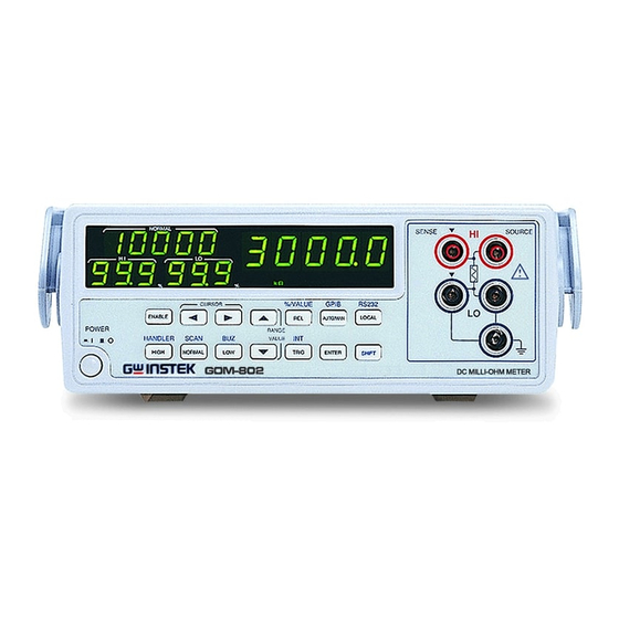
Page 7: Panel Introduction
GOM-802 DC MILLI-OHM METER GOM-802 DC MILLI-OHM METER USER MANUAL USER MANUAL 4. PANEL INTRODUCTION Figure 4-2. Rear Panel Figure 4-1. Front Panel ⎯ ⎯ ⎯ ⎯... -
Page 8: Front Panel
GOM-802 DC MILLI-OHM METER GOM-802 DC MILLI-OHM METER USER MANUAL USER MANUAL 5. OPERATION INTRODUCTION 4-1. Front Panel 5-1. The [SHIFT] key and function keys The [SHIFT] button is used to enable the secondary function of certain 1. Interface Indicator function keys that with blue symbols printed above. -
Page 9: Interface Operation
2) Press [▲]or[▼] can switch over the function, and 3 kinds of measurements “ohm”, “℃” and “TC” will be displayed on the panel. Operate the GOM-802 in a location with a suitable environment free from dust, direct exposition of sunlight, and strong effect of magnetic fields. - Page 10 GOM-802 DC MILLI-OHM METER GOM-802 DC MILLI-OHM METER USER MANUAL USER MANUAL 1) Under Compare function, press [NORMAL] button to turn on/off Low limit percentage setting: the function of normal value setting. 1) Under the compare function, press [LOW] to turn on/off the down...
-
Page 11: Temperature Measurement
GOM-802 DC MILLI-OHM METER GOM-802 DC MILLI-OHM METER USER MANUAL USER MANUAL Enable the measurement value percentage calculation, and the auto The recall function for the compare setting: range function will be annulled. 1) Under Compare function, set the high and low limit percentage of... -
Page 12: Temperature Compensation Measurement
GOM-802 DC MILLI-OHM METER GOM-802 DC MILLI-OHM METER USER MANUAL USER MANUAL (2) REL function (3) REL function Pre-set a reference value, then every value must minus the reference Pre-set a reference value, then every value must minus the reference value before displaying on the panel for the compare judgment. - Page 13 GOM-802 DC MILLI-OHM METER GOM-802 DC MILLI-OHM METER USER MANUAL USER MANUAL FAIL: Output “1” to GND, means the judgment of the compare Under the TRIG mode, change the range or power on the instrument, the “————” message will be displayed on the measurement displayed area, function is High or low.
- Page 14 GOM-802 DC MILLI-OHM METER GOM-802 DC MILLI-OHM METER USER MANUAL USER MANUAL 2) SCAN Operation Step 1. After the SCAN setting, the message of “READY” will be Set to SCAN mode from the resistance measurement mode, first displayed on the panel, SCAN interface starts output:...
- Page 15 GOM-802 DC MILLI-OHM METER GOM-802 DC MILLI-OHM METER USER MANUAL USER MANUAL Step 5: Scan channel 100, the sweep delay time is up: Step 3: Scan channel one, the sweep delay time is up: ∬ ∬ ∬ ∬ RELAY: RELAY: ∬...
-
Page 16: Measurement Techniques
GOM-802 DC MILLI-OHM METER GOM-802 DC MILLI-OHM METER USER MANUAL USER MANUAL 7. MEASUREMENT TECHNIQUES 7-1. 4-wire measurement (1) The 4-wire measurement can eliminate wire resistance and get accurate CONSTANT VOLTMETER CURRENT resistance. Please refer to the wiring method as Figure 7-1. -
Page 17: Temperature Measurement
GOM-802 DC MILLI-OHM METER GOM-802 DC MILLI-OHM METER USER MANUAL USER MANUAL 7-2. Temperature measurement (2) Temperature measurement sensor (1) Reference temperature The common usage for the resistance temperature detectors, RTD, is to The international Temperature Scale (ITS) is based on the following convert temperature into electro signal. -
Page 18: Maintenance
GOM-802 DC MILLI-OHM METER GOM-802 DC MILLI-OHM METER USER MANUAL USER MANUAL Example—Calculate the resistance of a PT-100 RTD at 100℃(T). The 8. MAINTENANCE following R (Ωat 0℃), alpha, beta, and delta values are used for the Qualified personnel execute the following instructions only. To avoid... -
Page 19: Cleaning
GOM-802 DC MILLI-OHM METER USER MANUAL 1) Make sure the power cord is unplugged. 2) Adjust the line voltage selector switch to the desired line voltage position. 3) A change in line voltage may also require a corresponding change of fuse value. Install the correct fuse value as listed on rear panel.
Need help?
Do you have a question about the GOM-802 and is the answer not in the manual?
Questions and answers