
Related Manuals for GW Instek PCS-1000


Summary of Contents for GW Instek PCS-1000
- Page 1 99 Washington Street Melrose, MA 02176 TestEquipmentDepot.com Precision Current Shunt Meter PCS-1000 USER MANUAL GW INSTEK PART NO. 82CS-1K000EB1 ISO-9001 CERTIFIED MANUFACTURER...
- Page 2 This manual contains proprietary information, which is protected by copyright. All rights are reserved. No part of this manual may be photocopied, reproduced or translated to another language without prior written consent of Good Will company. The information in this manual was correct at the time of printing. However, Good Will continues to improve products and reserves the rights to change specification, equipment, and maintenance procedures at any time without notice.
-
Page 3: Table Of Contents
Table of Contents Table of Contents SAFETY INSTRUCTIONS ........... 4 GETTING STARTED ............8 PCS-1000 Overview ........ 9 Appearance .......... 11 OPERATION ..............18 Set Up ..........19 Basic Operation ........25 COMMUNICATION INTERFACE ........42 Interface Configuration ......44 Command Syntax ......... -
Page 4: Safety Instructions
PCS-1000 User Manual AFETY INSTRUCTIONS This chapter contains important safety instructions that you must follow during operation and storage. Read the following before any operation to insure your safety and to keep the instrument in the best possible condition. Safety Symbols These safety symbols may appear in this manual or on the instrument. -
Page 5: Safety Guidelines
SAFETY INSTRUCTIONS Safety Guidelines Do not place any heavy object on the General instrument. Guideline Avoid severe impact or rough handling that CAUTION leads to damaging the instrument. Do not discharge static electricity to the instrument. Use only mating connectors, not bare wires, for ... - Page 6 PCS-1000 User Manual Location: Indoor, no direct sunlight, dust free, Operation almost non-conductive pollution (Note below) Environment Relative Humidity: Full accuracy to 80% RH, at 40°C Altitude: < 2000m Temperature: 0°C to 50°C (Pollution Degree) EN 61010-1:2001 specifies the pollution degrees and their requirements as follows.
- Page 7 SAFETY INSTRUCTIONS Power cord for the United Kingdom When using the instrument in the United Kingdom, make sure the power cord meets the following safety instructions. NOTE: This lead/appliance must only be wired by competent persons WARNING: THIS APPLIANCE MUST BE EARTHED IMPORTANT: The wires in this lead are coloured in accordance with the following code: Green/ Yellow:...
- Page 8 PCS-1000 User Manual ETTING STARTED This chapter describes the instrument in a nutshell, including its main features and front / rear panel introduction. PCS-1000 Overview ............9 Main Features ....................9 Accessories ....................10 Appearance ..............11 Front Panel ....................11...
-
Page 9: Getting Started
GETTING STARTED PCS-1000 Overview The PCS-1000 uses five high-precision shunt resistors as the basis for accurate current and voltage measurements. The 5 shunt ranges are 0.001Ω, 0.01Ω, 0.1Ω, 1Ω, 10Ω with a current measurement range of 300A, 30A, 3A, 300mA and 30mA, respectively. -
Page 10: Accessories
PCS-1000 User Manual Accessories Standard Part number Description Accessories Region dependant User manual Region dependant Power cord GTL-105A Alligator clip test leads (3A max): 1x red, 1x black GTL-207 Banana plug test leads: 1x red, 1x black GTL-240 USB Cable... -
Page 11: Appearance
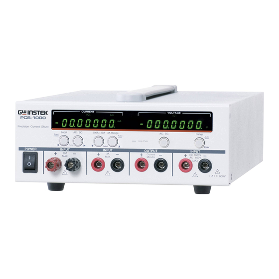
GETTING STARTED Appearance Front Panel CURRENT VOLTAGE 300A Auto ERROR Auto PCS-1000 Local AC / DC 300A / 30A 3A Range AC / DC Range Func Auto Auto : Long Push Func Select Enter POWER INPUT INPUT OUTPUT INPUT Current... - Page 12 ( Fused ) from over current: Fuse Rating: T3.5A, 600V Note: If the fuse is damaged, please contact your dealer or a GW Instek service center to replace the fuse. Warning: The maximum voltage difference between the negative terminal and earth cannot exceed 500Vpeak.
- Page 13 GETTING STARTED 6. Local Local: Press to switch to local Local AC / DC Func mode. Func Func: Long push to enter the Func (long push) Function menu. The Function menu is used to configure the instrument. 7. ◄ Func ► Use the Func arrows keys to Local AC / DC...
- Page 14 PCS-1000 User Manual 12. AC/DC Selects DC or AC voltage AC / DC measurement. (Voltage) 13. Range Manually select the voltage Range Auto measurement range: DC: 200mV, 2V, 20V, 200V, Enter 1000V AC: 200mV, 2V, 20V, 200V, 600V Secondary function that...
- Page 15 GETTING STARTED Autorange indicator for the 30mA, Auto 300mA and 3A ranges. If the Autorange indicator is off, then that indicates that the range has been manually selected. Milliamp unit indicator. Ampere unit indicator. 15. Voltage Meter RRENT VOLTAGE DCA 300A Auto ERROR Auto...
-
Page 16: Rear Panel
PCS-1000 User Manual Rear Panel INPUT ( NO FUSE ) 300A MAX. GPIB LINE RATING 50 / 60 Hz 35VA MAX. FUSE LINE SER.NO. LABEL 100VAC T200mA 120VAC 220VAC T100mA 240VAC DISCONNECT POWER CORD AND TEST LEADS BEFORE REPLACING FUSE 16. - Page 17 GETTING STARTED INPUT 19. AC/DC 300A Accepts AC/DC. ( NO FUSE ) 300A MAX. 300A maximum Terminal current input. 20. Fan Temperature controlled fan.
- Page 18 PCS-1000 User Manual PERATION Set Up ................19 Power Up ....................19 Rack Mount ....................20 Wire Gauge Considerations ..............21 Input Terminals ..................22 Basic Operation .............. 25 Selecting AC/DC Current ................25 Selecting the Current Range ..............25 Selecting AC/DC Voltage................
-
Page 19: Operation
In the event the calibration data and ROM check Note fails, CAL DATA FAIL will be displayed on the screen, as shown below. If the calibration data and ROM check fails, return the unit to an authorized GW Instek service center. CURRENT VOLTAGE DCA 300A Auto... -
Page 20: Rack Mount
PCS-1000 User Manual Rack Mount The PCS-1000 has two types of the racks, GRA- Background 419-E and the GRA-419-J for the EIA and JIS standards, respectively. Both types of the racks are 2U height racks and can fit 1 or 2 units. See the GRA-419 assembly manual for details. -
Page 21: Wire Gauge Considerations
(AWG) Cross Section Current (A) 0000 Withstand voltage wire recommendations WARNING As the PCS-1000 is a CAT II instrument, please ensure that the insulation capacity of the test cables exceed the DUT output voltage when performing current measurement. -
Page 22: Input Terminals
(GW Instek part number GTL-105A). The 3A terminal supports 3A, 30mA and 300mA ranges. Ensure any current or voltage sources are disabled WARNING before connecting any cables to the PCS-1000. 1. Turn the power switch off. Steps POWER 2. Connect the PCS-1000 in series Page 20 with the load and source. - Page 23 OPERATION Current Meter Connection Load + current input - current input Power Source Voltage Meter Connection Load + voltage input - voltage input Power Source...
- Page 24 PCS-1000 User Manual Voltage + Current Meter Connection Load Power Measure voltage at load terminal Source Measure voltage at source terminal Measure current Current Monitor – current monitor + current monitor Rear Panel Terminals...
-
Page 25: Basic Operation
OPERATION Basic Operation Selecting AC/DC Current AC or DC current can be measured when in Background measurement mode. 1. Press the AC/DC key under the CURRENT Steps meter current display to toggle between AC and DC current measurement. 2. The ACA or DCA indicator will be shown on the display. -
Page 26: Selecting Ac/Dc Voltage
PCS-1000 User Manual The selected range is indicated by the displayed Note unit (A or mA) and the number of significant digits before the decimal place: 3A: Unit=A; 1 significant digit 30mA: Unit=mA; 2 signicant digits 300mA: Uni=mA; 3 significant digits... -
Page 27: Selecting The Voltage Range
OPERATION Selecting the Voltage Range There are 5 selectable voltage ranges. The Background range can be manually or automatically selected. Press the Range key to cycle between each Manual Ranges voltage range. ACV: 200mV, 2V, 20V, 200V, 600V DCV: 200mV, 2V, 20V, 200V, 1000V The selected range is indicated by the displayed Note unit (V or mV) and the number of significant digits... -
Page 28: Voltage Range Conversion Table
PCS-1000 User Manual Voltage Range Conversion Table This table shows the relationship between AC and DC readings in various waveforms. Waveform Peak to Peak AC (True RMS) Sine 2.828 1.000 0.000 PK-PK Rectified Sine (full wave) 1.414 0.435 0.900 PK-PK Rectified Sine (half wave) 2.000... -
Page 29: Crest Factor Table
OPERATION Crest Factor Table Crest factor is the ratio of the peak signal amplitude to the RMS value of the signal. It determines the accuracy of AC measurement. If the crest factor is less than 3.0, voltage measurement will not result in error due to dynamic range limitations at full scale. -
Page 30: Using The Current Monitor Output
1Ω 0.1Ω 30 A 0.01Ω 300 A 0.001Ω 1. Set the PCS-1000 for normal operation, as Steps described previously in this chapter, page 25~27. Make note of the range used and the shunt that is used for that range. 2. Connect the current monitor output to a DVM. -
Page 31: How To Use The Function Menu
OPERATION How to Use the Function Menu The function menu allows you to view the Background software information, set the remote settings, the DCV, ACV, DCA, ACA averaging settings and other settings. Menu Item Range/Description Software Version Displays the software version on the display. - Page 32 PCS-1000 User Manual 1. Press and long push the Func key. Steps Local Func The software version will be displayed first. CURRENT VOLTAGE DCA 300A Auto ERROR Auto 2. Use the ◄ Func ► keys to Local AC / DC...
-
Page 33: View The Software Version
OPERATION The display uses a 7 segment LED display. The Note appendix has an ASCII Table if you have trouble understanding the characters on the LED display character set. See page 88. View the Software Version The display will show the software version. Background CURRENT VOLTAGE... -
Page 34: Default Settings
PCS-1000 User Manual Default Settings The Factory Default function will restore the Background default settings. 1. Long push the Func key. Steps The function menu will appear. 1. Use the ◄ Func ► keys to navigate to the FACTORY DEFAULT menu. -
Page 35: Setting The Usb-Uart Baud Rate
OPERATION Setting the USB-UART Baud Rate The baud rate settings are used for remote Background control via the USB B port. The USB B connection uses a virtual COM port to simulate a serial port (UART) connection. The baud rate can be set to 115200, 57600, 38400, 19200, 9600, 4800. -
Page 36: Setting The Gpib Address
PCS-1000 User Manual Setting the GPIB Address The GPIB port is used for remote control. The Background GPIB address can be set between 00 ~ 30. See the Communication Interface chapter on page 42 chapter for details on remote control. -
Page 37: Setting The Ad Speed
OPERATION Setting the AD Speed The ADC IC speed has a number of settings. Background The higher the setting, the lower the accuracy and resolution of the meter. Seconds (resolution): Range: 7 (6½ digits), 30 (5½ digits), 100 (4½ digits) 1. -
Page 38: Setting The Averaging Mode
PCS-1000 User Manual Setting the Averaging Mode There are two different types of averaging Background modes, SHIFT or TOTAL. SHIFT is a box car averaging mode while TOTAL will average all the collected samples to get the average value. SHIFT, TOTAL Range 1. -
Page 39: Setting The Averaging Number For The Dcv/Acv/Dca/Aca
OPERATION Setting the Averaging Number for the DCV/ACV/DCA/ACA Each of the different measurement modes Background (DCV, ACV, DCA, ACA) can have the number of averages set individually. 01 ~ 10, 20, 30, 40, 50, 60, 70, 80, 90, Range 1. Long push the Func key. Steps The function menu will appear. -
Page 40: Setting The Autozero Function
PCS-1000 User Manual Setting the Autozero Function The Autozero function will automatically Background perform a zero calibration when the unit is turned on. Enable, Disable Range 1. Long push the Func key. Steps The function menu will appear. 2. Use the ◄ Func ► keys to navigate to the AUTOZERO menu. -
Page 41: Beeper Settings
OPERATION Beeper Settings The beeper sound that is used for key presses Background and other system sounds can be turned on or off using this menu. On, Off Range 1. Long push the Func key. Steps The function menu will appear. 2. - Page 42 PCS-1000 User Manual OMMUNICATION INTERFACE This chapter describes basic configuration of IEEE488.2 based remote control. Interface Configuration ........... 44 Configure GPIB Interface ................44 GPIB Function Check ................. 45 USB Driver Installation ................48 USB Interface Settings ................50 USB Function Check ................... 53 Return to Local Operation ................
-
Page 43: Communication Interface
COMMUNICATION INTERFACE Sense Commands ..................69 [SENSe:]CURRent:RANGe ................. 69 [SENSe:]CURRent:DC:AVERage:COUNt ........... 70 [SENSe:]CURRent:AC:AVERage:COUNt ........... 70 [SENSe:]VOLTage:RANGe ................. 70 [SENSe:]VOLTage:DC:AVERage:COUNt ........... 71 [SENSe:]VOLTage:AC:AVERage:COUNt ........... 72 System Commands ................... 73 SYSTem:BEEPer:STATe ................73 SYSTem:ERRor................... 74 SYSTem:LOCal................... 74 SYSTem:REMote ..................75 SYSTem:RWLock ..................75 SYSTem:VERSion .................. -
Page 44: Interface Configuration
To use GPIB the GPIB address must first be set. 1. Connect the GPIB cable from the GPIB Configure GPIB controller to the PCS-1000. 2. Turn the PCS-1000 on. 3. Long push Func key to enter the Page 31 function menu. -
Page 45: Gpib Function Check
COMMUNICATION INTERFACE GPIB Function Check To test the GPIB functionality, National Background Instruments Measurement and Automation Explorer can be used. This program is available on the NI website, www.ni.com, via a search for the VISA Run-time Engine page, or “downloads” at the following URL, http://www.ni.com/visa/ Operating System: Windows XP, 7, 8 Requirements... - Page 46 PCS-1000 User Manual 1. From the Configuration panel access; My System>Devices and Interfaces>GPIBX (where X is the GPIB card number that is connected to the PCS-1000). 2. Click Scan for Instruments. 3. Double click on the Instrument 0 icon.
- Page 47 *IDN? is written in the Send test box. 6. Click on the Query button to send the *IDN? query to the instrument. 7. The following string should be returned: GWInstek, PCS-1000, xxxxxxxxx, Vx.xx (Manufacturer, model, serial, software version) 209.1711 mm.
-
Page 48: Usb Driver Installation
Requirements The following installation instructions only apply if Note the USB driver does not get automatically installed. 1. Connect the PCS-1000 to a PC using the USB Steps Type A-Type B cable (GTL-240). 2. The Windows Found New Hardware wizard should pop up asking you to install the device driver. - Page 49 COMMUNICATION INTERFACE choose Install this driver software anyway. 5. The PCS-1000 will now become available in the device tree under PORTS (COM & LPT) in the Windows Device Manager. If the Found New Hardware wizard does not Alternate appear or you wish to install the driver from...
-
Page 50: Usb Interface Settings
User Manual CD when prompted. Note: If the Windows Security pop-up appears, choose Install this driver software anyway. 4. The PCS-1000 will now become available in the device tree under PORTS (COM & LPT). If required, the USB drivers can be downloaded Note from http://www.ftdichip.com/Drivers/VCP.htm. - Page 51 7. Use the ◄ Func ► keys to go to the SAVE FUNC SET function. 8. Press the Enter key to save the baud rate settings. 1. Connect the PCS-1000 to the PC using the GTL- Edit UART 240 USB cable. Settings 2.
- Page 52 PCS-1000 User Manual...
-
Page 53: Usb Function Check
COMMUNICATION INTERFACE USB Function Check To test the USB functionality, National Background Instruments Measurement and Automation Explorer can be used. This program is available on the NI website, www.ni.com, via a search for the VISA Run-time Engine page, or “downloads” at the following URL, http://www.ni.com/visa/ Operating System: Windows XP, 7, 8, 8.1 Requirements... - Page 54 3. From the Configuration panel access; My System>Devices and Interfaces>Serial & Parallel>COMX (where X is the COM port number assigned to the PCS-1000). 4. Click on the Port Settings tab at the bottom. 5. Make sure the Baud rate settings are correct (PCS-1000 default = 9600 baud).
-
Page 55: Return To Local Operation
9. Click on the Query button to send the *IDN? query to the instrument. 10. The following string should be returned: GWInstek, PCS-1000, xxxxxxxxx, Vx.xx (Manufacturer, model, serial, software version) Return to Local Operation 1. Press the Local key to return to local operation. -
Page 56: Command Syntax
PCS-1000 User Manual Command Syntax Partial compatibility IEEE488.2 Compatible Partial compatibility Standard SCPI, 1999 SCPI commands follow a tree-like structure, Command Structure organized into nodes. Each level of the command tree is a node. Each keyword in a SCPI command represents each node in the command tree. - Page 57 COMMUNICATION INTERFACE A query is a simple or Query compound command followed by a question mark (?). A parameter (data) is returned. meas:curr:dc? Example Two or more commands on Compound the same command line. Compound commands are separated with either a semi- colon (;) or a semi-colon and a colon (;:).
- Page 58 PCS-1000 User Manual Commands and queries have two different Command Forms forms, long and short. The command syntax is written with the short form of the command in capitals and the remainder (long form) in lower case. The commands can be written in capitals or lower-case, just so long as the short or long forms are complete.
-
Page 59: Command List
COMMUNICATION INTERFACE <NR2> decimal 0.1, 3.14, 8.5 numbers <NR3> floating point 4.5e-1, 8.25e+1 <NRf> any of NR1, 2, 3 1, 1.5, 4.5e-1 <block data> Definitive length arbitrary block data. A single decimal digit followed by data. The decimal digit specifies how many 8-bit data bytes follow. - Page 60 PCS-1000 User Manual System SYSTem:BEEPer:STATe ..........73 Commands SYSTem:ERRor ............74 SYSTem:LOCal ............74 SYSTem:REMote ............75 SYSTem:RWLock ............75 SYSTem:VERSion ............75 SYSTem:OUTPut:FORMat .......... 75 Status STATus:OPERation:CONDition ........77 Commands STATus:OPERation:ENABle ........78 STATus:OPERation[:EVENt] ........78 STATus:PRESet ............79 STATus:QUEStionable:CONDition ......
-
Page 61: Configure Commands
COMMUNICATION INTERFACE Configure Commands CONFigure ..............61 CONFigure:CURRent ..........62 CONFigure:CURRent[:DC] ......... 62 CONFigure:CURRent:AC ..........63 CONFigure:VOLTage..........63 CONFigure:VOLTage[:DC] ......... 64 CONFigure:VOLTage:AC ..........65 CONFigure:AVERage:MODE ........65 CONFigure Query The CONFigure query will return both the current Description and voltage configuration as a string. Query Syntax CONFigure? Return Parameter <string>... -
Page 62: Configure:current
PCS-1000 User Manual CONFigure:CURRent Query The CONFigure:CURRent query will return the Description current range unit. Query Syntax CONFigure:CURRent? Return Parameter <string> Returns the current mode and range unit. Query Example CONF:CURR? > “DC 0.01” The range that is returned is the base unit. See the... -
Page 63: Configure:current:ac
COMMUNICATION INTERFACE Example CONF:CURR 20 Sets the current mode to DC and the range to 30A Example CONF:CURR Sets the current mode to DC. The range is not changed. CONFigure:CURRent:AC This command will set current mode to AC and set Description the range. -
Page 64: Configure:voltage[:Dc]
PCS-1000 User Manual Query Example CONF:VOLT? >”DC 0.1” The mode is DCV and the range is 200mV. The range that is returned is the base voltage unit. See Note the table below: Unit Voltage Range 1000 1000VDC 600ACV 200V 200mV... -
Page 65: Configure:voltage:ac
COMMUNICATION INTERFACE CONFigure:VOLTage:AC This command will set the voltage mode to AC Description and set the ACV range. If the range is not specified then it will not be changed. Syntax CONFigure:VOLTage:AC [<Range> | AUTO] <Range> Voltage range <NRf>: 0.0000001~630 Parameter The unit will automatically be set to the closest range. -
Page 66: Measure Commands
PCS-1000 User Manual Measure Commands MEASure ..............66 MEASure:CURRent[:DC] ..........66 MEASure:CURRent:AC ..........67 MEASure:VOLTage[:DC] ..........67 MEASure:VOLTage:AC ..........67 READ ................67 MEASure Query This query will return all the measurements. Description Query Syntax MEASure? Returns the current measurement voltage Return Parameter <NRf>... -
Page 67: Measure:current:ac
COMMUNICATION INTERFACE MEASure:CURRent:AC Query This query will return the AC current. Description Query Syntax MEASure:CURRent:AC? Returns the AC current. Return Parameter <NRf> Query Example MEAS:CURR:AC? >+9.9067E-1 Returns the AC current measurement (0.9A). MEASure:VOLTage[:DC] Query This query will return the DC voltage. Description Query Syntax MEASure:VOLTage[:DC]? - Page 68 PCS-1000 User Manual Query Syntax READ? Returns the current and voltage readings, Return Parameter <NRf> respectively <current>,<voltage> Query Example READ? > +9.9067E-1,+2.5E+1 Returns the current and voltage readings.
-
Page 69: Sense Commands
COMMUNICATION INTERFACE Sense Commands [SENSe:]CURRent:RANGe .......... 69 [SENSe:]CURRent:DC:AVERage:COUNt ....70 [SENSe:]CURRent:AC:AVERage:COUNt ....70 [SENSe:]VOLTage:RANGe .......... 70 [SENSe:]VOLTage:DC:AVERage:COUNt ....71 [SENSe:]VOLTage:AC:AVERage:COUNt ....72 [SENSe:]CURRent:RANGe Query Sets or queries the current range. Description Syntax [SENSe:]CURRent:RANGe {<Range>|AUTO} Query Syntax [SENSe:]CURRent:RANGe? <Range> Current range <NRf>: 0.00000001~305 Parameter / Sets the current range in amps. -
Page 70: [Sense:]Current:dc:average:count
PCS-1000 User Manual [SENSe:]CURRent:DC:AVERage:COUNt Query This query will set or return average count setting Description for DC current. Syntax [SENSe:]CURRent:DC:AVERage:COUNt (NR1) Query Syntax [SENSe:]CURRent:DC:AVERage:COUNt? The average count setting for DC current. Parameter / <NR1> Return Parameter 1~10, 20, 30, 40, 50, 60, 70, 80, 90, 100... -
Page 71: [Sense:]Voltage:dc:average:count
COMMUNICATION INTERFACE <Range> Sets the voltage range in volts. The unit Parameter / will automatically choose the closest Return Parameter range that is programmed. DC Range <NRf>: 0.0000001 ~ 1050 AC Range <NRf>: 0.0000001 ~ 600 Sets the range to AUTO. AUTO Example VOLT:RANG AUTO... -
Page 72: [Sense:]Voltage:ac:average:count
PCS-1000 User Manual [SENSe:]VOLTage:AC:AVERage:COUNt Query This query will set or return the average count Description setting for AC current. Syntax [SENSe:]VOLTage:AC:AVERage:COUNt <NR1> Query Syntax [SENSe:]VOLTage:AC:AVERage:COUNt? The average count setting for AC voltage. Return Parameter <NR1> 1~10, 20, 30, 40, 50, 60, 70, 80, 90, 100... -
Page 73: System Commands
COMMUNICATION INTERFACE System Commands SYSTem:BEEPer:STATe ..........73 SYSTem:ERRor ............74 SYSTem:LOCal ............74 SYSTem:REMote ............75 SYSTem:RWLock ............75 SYSTem:VERSion ............75 SYSTem:OUTPut:FORMat ......... 75 SYSTem:BEEPer:STATe Query Sets or queries the beeper status. Description Syntax SYSTem:BEEPer:STATe {0|1} Query Syntax SYSTem:BEEPer:STATe? Beeper on Parameter/ Return Parameter... -
Page 74: System:error
PCS-1000 User Manual SYSTem:ERRor Query Queries the error queue. Error messages are stored Description in FIFO order. Up to 20 error messages are stored in the error queue. The first error message that is stored is the first message that is returned. Each time a message is returned it is also cleared from the queue. -
Page 75: System:remote
COMMUNICATION INTERFACE SYSTem:REMote Sets the PCS-1000 operation to remote mode. All Description panel keys except the Local key are locked. Syntax SYSTem:REMote SYSTem:RWLock Sets the PCS-1000 operation to remote mode. All Description panel keys are locked, including the Local key. - Page 76 PCS-1000 User Manual Returns the output in +0.0E+0 ADC,-5.0E- NR3 format + unit. 7 VDC Returns the output in +0.00000000,- NR2 format. 0.0000004 Returns the output in +0.00000000 ADC,- NR2 format + unit. 0.0000004 VDC Syntax SYSTem:OUTPut:FORMat (0~3) Query Syntax...
-
Page 77: Status Commands
COMMUNICATION INTERFACE Status Commands STATus:OPERation:CONDition ......... 77 STATus:OPERation:ENABle ........78 STATus:OPERation[:EVENt] ........78 STATus:PRESet ............79 STATus:QUEStionable:CONDition ......79 STATus:QUEStionable:ENABle ........80 STATus:QUEStionable[:EVENt] ........80 STATus:OPERation:CONDition Query Returns the contents of the Standard Operation Description Condition Register. Bit weight Description Calibrating Not used Measuring... -
Page 78: Status:operation:enable
PCS-1000 User Manual STATus:OPERation:ENABle Query Returns or sets the contents of the Standard Description Operation Enable Register. Bit weight Description Calibrating Not used Measuring Not used Config Change 9~15 Not used Syntax STATus:OPERation:ENABle (0~65535) Query Syntax STATus:OPERation:ENABle? 0~65535: Indicates the bit weight of the Parameter / <NR1>... -
Page 79: Status:preset
COMMUNICATION INTERFACE Example SYST:OPER? >256 Indicates that bit 8 has been latched. STATus:PRESet Resets the Standard Event Enable Register, the Description Questionable Data Enable Register and the Standard Operation Enable Register to their default state. Syntax STATus:PRESet STATus:QUEStionable:CONDition Query Returns the contents of the Questionable Data Description Condition Register. -
Page 80: Status:questionable:enable
PCS-1000 User Manual STATus:QUEStionable:ENABle Query Returns or sets the contents of the Questionable Description Data Enable Register. Bit weight Description Volt Overload Current Overload 2~15 Not used Syntax STATus:QUEStionable:ENABle (0~65535) Query Syntax STATus:QUEStionable:ENABle? 0~65535: Indicates the bit weight of the Parameter / <NR1>... -
Page 81: Common Commands
*IDN? Query Returns the manufacturer, model number, serial Description number and software version number. Query Syntax *IDN? Query Example *IDN? >GWInstek,PCS-1000,xxxxxxxxx,Vx.xx *ESE Query Returns or sets the contents of the Standard Event Description Enable Register. Bit weight Description Operation Complete... -
Page 82: Esr
PCS-1000 User Manual Syntax *ESE (0~255) Query Syntax *ESE? 0~255: Indicates the bit weight of the Parameter / <NR1> Return Parameter Standard Event Enable Register. Query Example *ESE 189 Enables all bits except for bit 1 and 6. *ESR? Query Queries the Standard Event Register. -
Page 83: Stb
COMMUNICATION INTERFACE ERR: Error queue QUES: Questionable Data Register summary bit MAV: Message available bit ESB: Event summary bit OPER: Standard Operation Register summary bit Syntax *SRE (0~255) Query Syntax *SRE? 0~255: Indicates the bit weight of the Parameter / <NR1>... -
Page 84: Psc
PCS-1000 User Manual Query Example *STB? >4 Indicates that there is a message in the error queue. *PSC Query The Power on Status Clear command enables the Description unit to clear the Service Request Enable, the Standard Event Enable and other event enable registers at power up. -
Page 85: Tst
COMMUNICATION INTERFACE *TST? Query Self-test query. This query will initiate a self-test Description and return the result. Query Syntax *TST? All tests have passed. Parameter One of more tests have failed. Query Example *TST? >0 Indicates that all tests have passed. *CLS The Clear Status command will clear the Status Description... -
Page 86: Status Registers
PCS-1000 User Manual Status Registers Questionable Data Register Condition Event Enable Voltage Overload Current Overload Not Used Not Used Output Not Used Buffer Not Used Not Used Not Used Not Used Not Used Not Used Error Que Not Used Not Used... -
Page 87: Error Messages
COMMUNICATION INTERFACE Error Messages Command Errors 0,"No error" -101,"Invalid character" -102,"Syntax error" -103,"Invalid separator" -108,"Parameter not allowed" -109,"Missing parameter" -113,"Undefined header" -121,"Invalid character in number" -123,"Numeric overflow" -131,"Invalid suffix" -148,"Character data not allowed" -151,"Invalid string data" Execution Errors -222,"Data out of range" -224,"Illegal parameter value"... -
Page 88: Appendix
PCS-1000 User Manual PPENDIX PCS Default Settings The following default settings are the factory configuration settings when the unit first ships. See page 34 to restore the factory default settings. Initial Settings Default Setting Current Meter Voltage Meter Current Range... -
Page 89: Pcs-1000 Specifications
APPENDIX PCS-1000 Specifications The specifications apply when the PCS is powered on for at least 30 minutes. General Power Supply 100 V / 120 V / 220 V / 240 V ±10% Power Line Frequency 50/60Hz Operating Environment Full accuracy for 0˚C to 50˚C, Full accuracy to 80% R.H. - Page 90 PCS-1000 User Manual AC Characteristics True RMS AC 1 Year Temperature Range Frequency Voltage 23˚C ± 5˚C Coefficient/˚C 200.0000 mV 0.005 + 0.005 2.000000 V 0.005 + 0.005 45 Hz - 2 kHz 0.5 + 0.05 20.00000 V 2 kHz - 10 kHz 1.0 + 0.05...
-
Page 91: Pcs Dimensions
APPENDIX PCS Dimensions 25.6 INPUT CURRENT VOLTAGE ( NO FUSE ) 300A MAX. 300A Auto ERROR Auto PCS-1000 GPIB Precision Current Shunt Precision Current Shunt Local AC / DC 300A / 30A 3A Range AC / DC Range Func Auto... -
Page 92: Declaration Of Conformity
PCS-1000 User Manual Declaration of Conformity GOOD WILL INSTRUMENT CO., LTD. No. 7-1, Jhongsing Rd, Tucheng Dist., New Taipei City 236, Taiwan GOOD WILL INSTRUMENT (SUZHOU) CO., LTD. No. 69 Lushan Road, Suzhou New District Jiangsu, China. declare that the below mentioned product... -
Page 93: Index
INDEX NDEX AC/DC Current ......25 LCD conversion ......88 AC/DC Voltage ......26 List of features ......9 Accessories ......... 10 Overview ........9 AD speed ........37 Power on/off Autozero function ...... 40 safety instruction ......5 Power up ........19 Average mode ......
Need help?
Do you have a question about the PCS-1000 and is the answer not in the manual?
Questions and answers