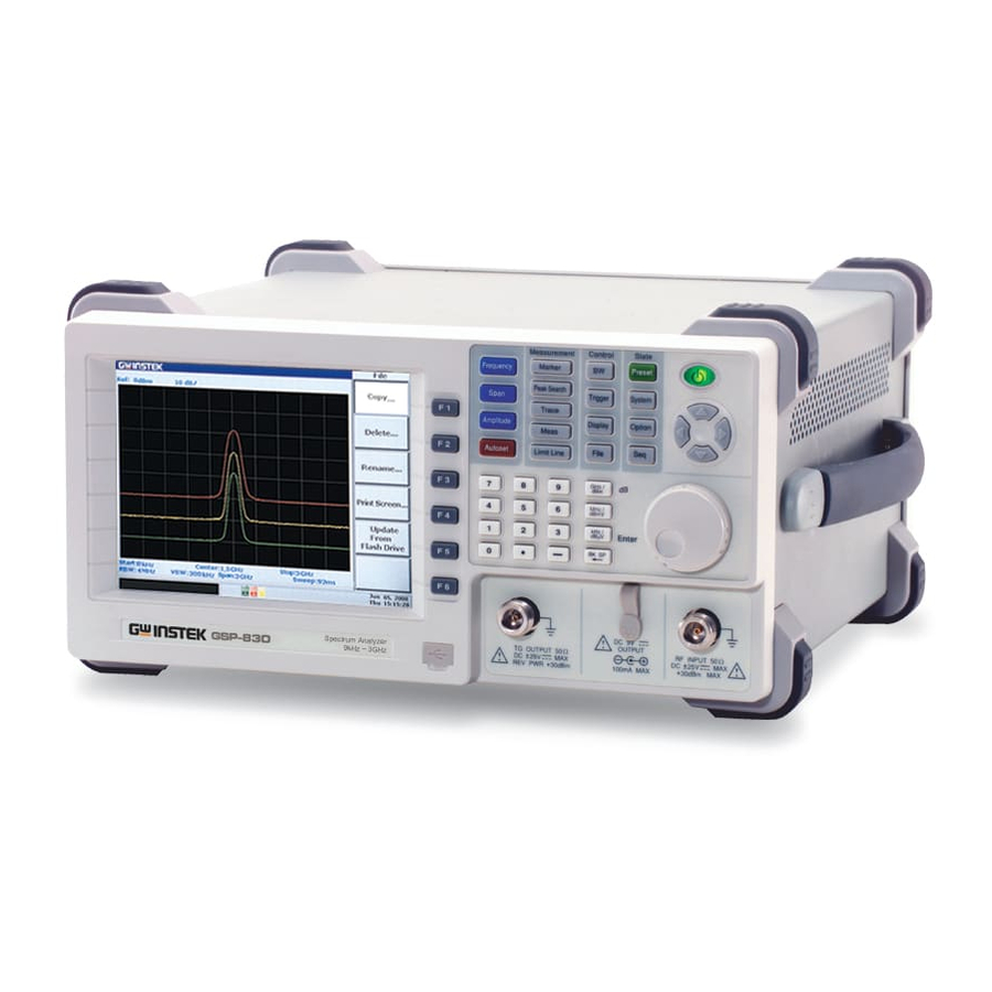
GW Instek GSP-830 User Manual
3.0ghz spectrum analyzer
Hide thumbs
Also See for GSP-830:
- User manual (181 pages) ,
- User manual (181 pages) ,
- User manual (181 pages)

Related Manuals for GW Instek GSP-830


Summary of Contents for GW Instek GSP-830
- Page 1 3.0GHz Spectrum Analyzer GSP-830 USER MANUAL GW INSTEK PART NO. 82SP-83000MA1 ISO-9001 CERTIFIED MANUFACTURER...
- Page 2 This manual contains proprietary information, which is protected by copyrights. All rights are reserved. No part of this manual may be photocopied, reproduced or translated to another language without prior written consent of Good Will company. The information in this manual was correct at the time of printing. However, Good Will continues to improve products and reserves the rights to change specification, equipment, and maintenance procedures at any time without notice.
-
Page 3: Table Of Contents
Table of Contents SAFETY INSTRUCTIONS ................. 7 Safety Symbols .................. 7 Safety Guidelines ................8 GETTING STARTED ..................11 GSP-830 Characteristics ..............12 Package Contents ................13 Front Panel Overview ............... 14 Rear Panel Overview ................ 17 Display Overview ................20 Tilt Stand & Power Up ..............22 Error Check ..................23... - Page 4 GSP-830 User Manual Activate/de-activate marker(s)............64 Move marker(s)................67 Show Markers in Table ..............69 PEAK SEARCH ....................70 Search Signal Peaks .................71 Show Peak Table................73 TRACE ......................75 View traced waveform ..............76 Move Marker to Trace ..............78 Run Trace Math ................80 Select Signal Detection Mode............82 POWER MEASUREMENT................
- Page 5 PRESET ...................... 126 SYSTEM.......................127 Save/Recall Panel Setting ............128 Configure Communication Interface..........129 View System Information..............131 Set Date/Time .................135 Synchronize GSP-830 with Other Device........136 Select Menu Language..............138 Service operation menu ............... 138 SEQUENCE....................139 Edit Sequence..................140 Run Sequence ..................143 TRACKING GENERATOR................145 DEMODULATOR ..................
- Page 6 Connect Software ................155 Use Software .................. 158 REMOTE CONTROL..................161 Configure Interface ............... 162 Command Syntax................164 Command Set.................. 165 FAQ......................178 Appendix ....................180 GSP-830 Specification ..............180 Optional Items Specifications ............182 Declaration of Conformity ............184 INDEX ......................185...
-
Page 7: Safety Instructions
GSP-830. Safety Symbols These safety symbols may appear in this manual or on GSP-830. Warning: Identifies conditions or practices that could WARNING result in injury or loss of life. -
Page 8: Safety Guidelines
Do not disassemble GSP-830 unless you are qualified • as service personnel. (Note) EN 61010-1:2001 specifies the measurement categories and their requirements as follows. GSP-830 falls under category II. Measurement category IV is for measurement performed at the • source of low-voltage installation. - Page 9 Temperature: 18°C to 28°C • (Note) EN 61010-1:2001 specifies the pollution degrees and their requirements as follows. GSP-830 falls under degree 2. Pollution refers to “addition of foreign matter, solid, liquid, or gaseous (ionized gases), that may produce a reduction of dielectric strength or surface resistivity”.
- Page 10 GSP-830 User Manual Power cord for the United Kingdom When using GSP-830 in the United Kingdom, make sure the power cord meets the following safety instructions. NOTE: This lead / appliance must only be wired by competent persons WARNING: THIS APPLIANCE MUST BE EARTHED...
-
Page 11: Getting Started
錯誤! 尚未定義樣式。 ETTING STARTED This chapter describes GSP-830 in a nutshell, including its main features, package contents, and front / rear / display panel introduction. After going through the overview, follow the Power-up sequence and Functionality check section to properly setup GSP-830. -
Page 12: Gsp-830 Characteristics
GSP-830 User Manual GSP-830 Characteristics GSP-830 is a middle- to high-range digital storage spectrum analyzer suitable for wide range of applications, such as production testing, research, and field verification. Performance Low noise floor: -117dBm @600MHz, 3k RBW • Fast sweep: 50ms ~ 25.6s range •... -
Page 13: Package Contents
錯誤! 尚未定義樣式。 Package Contents Contact your dealer in case there is a missing item. GSP-830 + pre-installed The following, if bundled, are factory installed items. optional items Option01 Tracking Generator • Option03 ±1ppm Stability module • Option04 300Hz RBW •... -
Page 14: Front Panel Overview
GSP-830 User Manual Front Panel Overview LCD Display TFT Color display, 640x480 resolution. For display setting details, see page110. F1~F6 Function Keys Soft keys linked to the menu that appears on the right side of the display. Main Keys Frequency key (page42), together with... - Page 15 File key (page116) saves/recalls/deletes trace waveform, limit line, amplitude correction, sequence (macro), and panel setup. It also saves display image through USB port. State Keys Preset key (page41or126) resets GSP-830 Preset to a predefined state. System key configures date/time (page135), GPIB/RS232C interface System (page129), and language (page138).
- Page 16 GSP-830 User Manual Power Key Power key selects the power state between Standby mode (Red LED On) and Power On mode (Green LED On). For main power On/Off, use the Power switch on the rear panel. For power up sequence, see page22.
-
Page 17: Rear Panel Overview
錯誤! 尚未定義樣式。 Rear Panel Overview Frequency Adjusts the internal reference signal ☺ Adjustment Point frequency; for service operation only. GPIB Connector Optional 24 pin female GPIB connector (Optional) for remote control (page161). For interface setting details, see page130. USB Connector Type B mini connector for PC software connection (page153) and remote control (page161). - Page 18 GSP-830 User Manual Phone Output 3.5mm phone jack for audio output. (Optional) Available when the optional Demodulator is installed. For details, see page147. Battery Pack Optional battery pack for portable (Optional) usage. Installed together with DC operation module. For details, see page151.
- Page 19 Reference Output Outputs +5V TTL, 10MHz reference signal used for synchronizing GSP-830 with external device. For details, see page136. Reference Input Accepts a signal from an external device, used for synchronization with GSP-830. For details, see page137.
-
Page 20: Display Overview
GSP-830 User Manual Display Overview Traces & Waveforms Input signal and trace that appears on the main display area. Input signal & TraceA: Green, TraceB: Red, TraceC: Yellow. For trace details, see page75. Title Title of the current display. For details, see page112. -
Page 21: Status Icon Overview
錯誤! 尚未定義樣式。 Status Icon The icons showing various system conditions. See the below Status Icon Overview for details. Test Result/ Error The result of the Pass/Fail test using the Limit lines Message (page96) or the system error messages (page131). Command Window Shows the current status of the selected menu or the entered parameters such as frequency and amplitude. -
Page 22: Tilt Stand & Power Up
GSP-830 User Manual Tilt Stand & Power Up Tilt stand Low angle High angle 1. Connect the Power cord to the Power Up rear panel socket. 2. Turn On the Main power switch. 3. The ON/STBY key on the front panel turns red. -
Page 23: Error Check
錯誤! 尚未定義樣式。 Error Check This section assumes that GSP-830 is already powered • up (page22). 1. Check system error Check the bottom of the display, next to the command window, to see if there is any error message. Center : 1.5GHz... -
Page 24: Functionality Check
• these steps to make sure it is functionally stable. 1. Feed a signal Input a signal to check if GSP-830 correctly shows the waveform on the display. There are two ways to feed an input signal. Feed the DUT signal If the Device Under Test is already available, connect the output signal to the RF input terminal. - Page 25 錯誤! 尚未定義樣式。 Check the peak frequency and amplitude that appear on the top right corner of the display. To move the marker, use the Scroll knob or Left/Right key Internal auxiliary signal, -30dBm @100MHz Peak frequency/amplitude If the displayed value does not match the actual signal, contact the service center.
-
Page 26: Quick Reference
Preset key. Use this chapter as a handy reference when you need quick access to the intended operation, and when you need to get an overview of GSP-830 functionalities. Shortcut Operation Shortcuts ................27 Menu Tree Frequency, Span, Autoset, Amplitude(1 of 2) ........ -
Page 27: Operation Shortcuts
錯誤! 尚未定義樣式。 Operation Shortcuts Here is the list of operations introduced in this manual and their shortcuts. Frequency and Span Set Center Frequency and Span Frequency→F1, Span→F1 Set Start and Stop Frequency Frequency→F2, F3 Set Frequency Step Frequency→F4 Activate Full Span (3.0GHz) Span→F2 Activate Zero Span (Time Domain) Span→F3... - Page 28 GSP-830 User Manual Marker Activate Normal Marker Marker→F1, F2 Activate Delta Marker Marker→F1, F2, F3 Activate All Normal Markers Marker→F6→F3 Move Marker to Peak Marker→F4 or Peak Search→F1 Move Marker and Peak to Center Marker→F4, F5 or Peak Search→F5 Track Marker on Peak Peak Search→F6→F4...
- Page 29 錯誤! 尚未定義樣式。 Power Measurement Activate ACPR Meas→F2 Set ACPR Main Channel Bandwidth Meas→F1→F1 Set ACPR Channel Space Meas→F1→F2 Set Adjacent Channel Offset Meas→F1→F4→F2, F4 Set Adjacent Channel Bandwidth Meas→F1→F4→F1, F3 Move ACPR Channel Up Meas→F4 Move ACPR Channel Down Meas→F5 Activate OCBW Meas→F3 Set OCBW Channel Bandwidth...
- Page 30 GSP-830 User Manual Bandwidth Select RBW BW→F1 Select VBW BW→F2 Set Sweep Time BW→F3 Set Trace Average Number BW→F4 or Trace→F6→F1 Reset RBW/VBW/Sweep to Auto BW→F5 Trigger Select Free Run (Default) Trigger→F1 Select Video/External Trigger Trigger→F2 Select Trigger Mode Trigger→F3 Set Trigger Delay Trigger→F4...
- Page 31 錯誤! 尚未定義樣式。 Copy Selected File File→F1→F4 Select File for Deletion File→F2→F1→F1~F5 Delete Selected File File→F2→F2 Rename File File→F3→F1 Confirm New File Name File→F3→F2 Save Display Image to USB Drive File→F4→F1→F2 Rename File in USB Drive File→F4→F1→F1 Preset Recall Preset Panel Setting Preset System Save Setup...
- Page 32 GSP-830 User Manual Activate FM Demodulator Option→F2→F1 Activate AM Demodulator Option→F2→F2 Activate Phone Output Option→F2→F3 Set Phone Output Volume Option→F2→F4 Set Squelch Level Option→F2→F5 View Battery Level Option→F3 Set Ext. Reference Signal Frequency Option→F4 Sequence Select Sequence Set Sequence→F1, F2 Start Sequence Edit Sequence→F3→F1...
-
Page 33: Menu Tree
錯誤! 尚未定義樣式。 Menu Tree Preset key does not have menu. Frequency, Span, Autoset, Amplitude(1 of 2) Frequency Span Autoset Center Span Autoset 1.5 GHz 3 GHz Start Amp.Floor Full Span 0 kHz Auto Man Stop Span Zero Span 3 GHz Auto Man Step Last Span... - Page 34 GSP-830 User Manual Amplitude (2 of 2), Marker Amplitude Ref.Level Select Edit... -30.0dBm 1 2 3 4 5 Correction Scale dB/Div Delete 10 5 2 1 Units... Delete All.. Ext.Gain Undelete Save Now Corrections.. More Return Return Return InputZ 50Ω...
- Page 35 錯誤! 尚未定義樣式。 Peak Search, Trace Peak Search Peak Table Pk Search Peak Sort Next Peak Freq Amp Next Pk Pk Threshold Right Next Pk Track Left Mkr Center Min Search More Return Trace Trace Clear A+B A Trace Math.. Peak Hold Detection..
- Page 36 GSP-830 User Manual Measurement, Limit Line Meas Channel CH BW Adj CH BW1 Setup... ACPR CH SPC Adj CH Offs1 OCBW OCBW % Adj CH BW2 ADJ CH CH Up Adj CH Offs2 Offset... CH Down More Return Return N dB BW...
- Page 37 錯誤! 尚未定義樣式。 BW, Trigger, Display Trigger Free Run Auto Manu Trigger Condition Auto Manu Video Ext. Swp Tm Trigger Mode Auto Manu Norm. Sgl. Cont. Trigger Delay 50ms Trigger Freq All Auto 1.5GHz Run Now Display Clear Title Upper LCD Dimmer (Capital Display Line Lower...
- Page 38 GSP-830 User Manual File File File Type... Source.. Type Type File Delete Now Destination.. Type Edit File Name Copy Now Return Return File File Type Trace Copy... Edit File Name Int. Ext. Limit Delete... Confirm Int. Ext. Correction Rename... Int.
- Page 39 錯誤! 尚未定義樣式。 System System Save/Recall Baud Setup Setup.. 115200 1 2 3 4 5 GPIB Add Parity Setup None 6 7 8 9 10 Stop Serial Port.. Save Now Aux Sig Data Recall Now Service... More... Return Return System Date... Year Clock...
- Page 40 GSP-830 User Manual Option, Sequence Option TG... Demod... TG Level Execute Battery Normalization.. Ext Ref Freq Norm Corr Volume 10MHz Squelch Ref Value Return Return Return Select Seq Seq.Index Start Edit 1 2 3 4 5 1 2 3 4 5...
-
Page 41: Preset Contents
錯誤! 尚未定義樣式。 Preset Contents Preset These are the settings that appear when pressing the Preset key Frequency Center: 1.5GHz Stop: 3GHz Start: 0Hz Step: 1MHz Span 3GHz Amplitude Ref.level: 0dBm Scale: 10dB/ Unit: dBm External Gain: 0dB Correction: Off Input Z: 50Ω Autoset Amplitude Floor: Auto Span: Auto... -
Page 42: Frequency/Span
GSP-830 User Manual REQUENCY/ Frequency key, together with Span key, sets the frequency scale. Two methods are available. Center-and-Span method defines the center point and the surrounding frequency range. Start-and-Stop method defines the beginning and the end of the frequency range. -
Page 43: View Signal (Center And Span)
錯誤! 尚未定義樣式。 View Signal (Center and Span) Center-and-Span method defines the Center frequency and the left/right bandwidth (Span) to locate the signal. Set frequency adjustment step Background Frequency adjustment step defines the Arrow key resolution for Center, Start, and Stop frequency. Panel operation 1. -
Page 44: Set Frequency Span
GSP-830 User Manual Display Center Frequency reading Set Frequency Span Panel operation 1. Press the Span key. Span 2. Press F1 (Span). Span 3 GHz 3. Enter the value using the numerical keys, Arrow key, and μ Scroll knob. Range 2kHz ~ 3GHz * Arrow key &... -
Page 45: View Signal (Start And Stop)
錯誤! 尚未定義樣式。 View Signal (Start and Stop) Start-and-Stop method defines the beginning (Start) and the end (Stop) of the frequency range. Set frequency adjustment Step Background Frequency adjustment step defines the Arrow key resolution for Center, Start, and Stop frequency. Panel operation 1. -
Page 46: Set Stop Frequency
GSP-830 User Manual Display Start Frequency Frequency reading Set Stop frequency Panel operation 1. Press the Frequency key. Frequency 2. Press F3 (Stop). Stop 3 GHz 3. Enter the value using the numerical keys, Arrow key, and μ Scroll knob. -
Page 47: Full/Zero Span
錯誤! 尚未定義樣式。 Full/Zero Span Full or Zero Span sets the span to extreme values: 3.0GHz (full) or 0kHz (zero). They provide faster ways to view signals in certain situations, such as in time domain (zero span) for viewing modulation or in full span for viewing frequency unknown signal. -
Page 48: Recall The Last Span Setting
GSP-830 User Manual Zero span also sets these parameters to fixed values. Start frequency: same as the Center frequency • Stop frequency: same as the Center frequency • Display The diagram shows an example of observing the amplitude modulation of the input signal. -
Page 49: Amplitude
Amplitude Correction adjusts the frequency response distortion caused by external networks. Pre-Amplifier is an optional item that boosts the level of weak input signal before entering GSP-830. You can also set input impedance level according to the application needs. Vertical Scale Set reference amplitude level............50... -
Page 50: Set Vertical Scale
GSP-830 User Manual Set Vertical Scale Vertical display scale is defined by the reference amplitude level, vertical amplitude range, measurement unit, and external gain/loss setting. Set reference amplitude level The reference level defines the uppermost display level. Panel operation 1. Press the Amplitude key. -
Page 51: Select Amplitude Scale
錯誤! 尚未定義樣式。 Select Amplitude scale Panel operation 1. Press the Amplitude key. Amplitude 2. Press F2 (Scale dB/Div) Scale dB/Div 10 5 2 1 repeatedly to select the scale. Range 10, 5, 2, 1 dB/Div Display Scale reading Select Amplitude Unit Panel operation 1. -
Page 52: Set External Offset Level
GSP-830 User Manual Set External Offset level Background External offset compensates amplitude gain or loss caused by an external network or device. Panel operation 1. Press the Amplitude key. Amplitude 2. Press F4 (Ext.Gain). Ext.Gain 3. Enter the value using the numerical keys. -
Page 53: Amplitude Correction
On. Correct amplitude step by step Example description In this example, the network between GSP-830 and DUT distorts the waveform and pushes the level down at around 2.4GHz. Amplitude correction can fix the level. Correction level In this example the amplitude around 2.4GHz is boosted... - Page 54 GSP-830 User Manual Diagram Network Waveform (before The frequency response is distorted (non-flat) and the correction) level is attenuated by 2 ~ 3dB. 1. Enter correction edit 1. Press the Amplitude key. Amplitude mode 2. Press F5 (Corrections). Corrections.. 3. Press F1 (Edit). The display Edit...
- Page 55 錯誤! 尚未定義樣式。 2. Select correction set Press F1 (Select) repeatedly to Select select the correction set. 5 sets, 30 1 2 3 4 5 points each, are selectable. Example: correction set 3 selected Select 1 2 3 4 5 3a. Add correction point 1.
-
Page 56: Correction
GSP-830 User Manual Example: point 3 deleted Freq. (MHz) Gain Freq. (MHz) Gain 2200 2200 2300 2300 2400 2500 2500 2600 2600 4. Save correction set 1. Press F5 (Save Now). The Save Now edited data is saved internally. 2. Press F6 (Return) to go back Return to the previous menu. -
Page 57: Recall Existing Correction Set
錯誤! 尚未定義樣式。 6. Select and press F1 (No) or F2 (Yes) for confirm. The whole data in the specified correction set is deleted. 7. Press F6 (Return) repeatedly to Return go back to previous menus. Recall existing correction set Panel operation 1. -
Page 58: Use Pre-Amplifier Gap-801 (Optional)
Amplitude 11.5dB typical Connection 1. Connect the pre-amplifier GAP-801 between the input terminal and DUT signal output. 2. Connect GAP-801 power input to GSP-830 DC 9V output. Power RF Input 3. The signal level is amplified by 11.5dB (typical). Amplitude boost 格式化: 標題... -
Page 59: Set Input Impedance
錯誤! 尚未定義樣式。 Set Input Impedance Select input impedance (50Ω/75Ω) Background In most cases, the default 50 Ω is appropriate. Use 75 Ω when specifically required, such as in Cable TV signals. Panel operation 1. Press the Amplitude key. Amplitude 2. Press F6 (More). More 3. -
Page 60: Autoset
GSP-830 User Manual UTOSET Autoset function checks the input signal configuration and automatically setup the suitable horizontal and vertical scale. The amplitude floor for limiting the search range, and frequency observation span for limiting the viewing range are customizable according to the application needs. - Page 61 錯誤! 尚未定義樣式。 Example: before Autoset Start frequency: 0kHz Stop frequency: 3GHz Span: 3GHz Signal peak: 100MHz Center frequency: 1.5GHz Reference level: −10dBm Example: after Autoset Start frequency: 97.5MHz Stop frequency: 102.5MHz Span: 5MHz Signal peak: 100MHz Center frequency: 100MHz Reference level: −30dBm RBW/VBW/Sweep Setting All the three BW related parameters, RBW, VBW, and after Autoset...
- Page 62 GSP-830 User Manual Limit vertical search range Background You can set the amplitude floor so that the signals lower than the setting will be ignored from Autoset search. Panel operation 1. Press the Autoset key. Autoset 2. Press F2 (Amp. Floor) to switch Amp.Floor...
-
Page 63: Marker
錯誤! 尚未定義樣式。 ARKER A Marker shows the frequency and amplitude of a waveform point. GSP-830 can activate up to 5 Markers or Marker pairs simultaneously. Marker Table helps editing and viewing multiple Markers in a single display. You can also enable/disable all Markers at once. Delta Marker shows the frequency and amplitude difference between the reference Marker. -
Page 64: Activate/De-Activate Marker(S)
GSP-830 User Manual Activate/de-activate marker(s) Menu tree F3 ~ F5 are available only when the Marker is On (activated). Range Normal marker Delta marker 5 pairs Amplitude −120 ~ +20dBm, 0.1dB resolution −73.01~+66.99dBmV, 0.01dB resolution −13.01~+126.99dBuV, 0.01dB resolution Frequency 0kHz ~ 3.0GHz... -
Page 65: Activate All 5 Normal Markers At Once
錯誤! 尚未定義樣式。 Display The upper right corner of the display shows the active marker. Marker ID, Frequency, Amplitude Activate all 5 normal markers at once Panel operation 1. Press the Marker key. Marker 2. Press F6 (More). More 3. Press F3 (All Mkrs On) to turn All Mkrs On all 5 normal markers. -
Page 66: Activate Delta Marker(S)
GSP-830 User Manual Activate delta marker(s) Panel operation 1. Press the Marker key. Marker 2. Press F1 (Marker) repeatedly Marker to select the marker ID from 1 1 2 3 4 5 to 5. 3. Press F2 (On) and turn On the selected marker. -
Page 67: Move Marker(S)
錯誤! 尚未定義樣式。 Move marker(s) This section assumes at least one marker is already activated (page64). Marker frequency positions can be set manually, or to specific locations using the menu shortcuts. Move marker manually Panel operation 1. Check the active marker at the top right corner of the display. -
Page 68: Move Marker And The Highest Peak To The Center
GSP-830 User Manual Move marker and the highest peak to the center Method 1 1. Check the active marker at the top right corner of the display. 2. Press the Marker key. Marker 3. Press F4 (To Peak). The marker To Peak moves to the signal peak. -
Page 69: Show Markers In Table
錯誤! 尚未定義樣式。 Move marker to a trace Panel operation 1. Check the active marker at the top right corner of the display. 2. Press the Marker key. Marker 3. Press F6 (More). More 4. Press F1 (Marker Trace). Marker Trace Auto A B C Range Auto... -
Page 70: Peak Search
GSP-830 User Manual EAK SEARCH Peak search automatically finds out the signal peaks in various conditions, such as next highest peak and minimum peak. Peak Search overlaps its feature with Marker function, and it is best to use the two together. -
Page 71: Search Signal Peaks
Search Signal Peaks Peak Search puts a marker on the target signal peak. If no marker has been activated, GSP-830 automatically activates marker 1. The peak signal frequency and amplitude appear at the top right corner of the display. Marker ID, Frequency, Amplitude... -
Page 72: Search The Next Highest Peak
GSP-830 User Manual Search the next highest peak The marker keeps moving to the next highest peak, in descending order. Panel operation 1. Press the Peak Search key. Peak Search 2. Press F2 ~ F4 repeatedly. Next Peak Next Peak: moves the marker to the next highest peak. -
Page 73: Show Peak Table
錯誤! 尚未定義樣式。 Search the minimum amplitude Panel operation 1. Press the Peak Search key. Peak Search 2. Press F6 (More). More 3. Press F5 (Min Search). The Min Search active marker moves to the deepest valley in the trace. Minimum Amplitude Show Peak Table Activate peak table Panel operation... -
Page 74: Set Peak Threshold
3. Press F1 (Peak Table On). Peak Table 4. Press F3 (Pk Threshold On). Pk Threshold 5. A horizontal line appears on the display. GSP-830 searches and lists peaks only below this threshold amplitude. 6. Use the Arrow key or the Scroll knob to move the threshold line. -
Page 75: Trace
B, and C, are available for accumulating the peak level, freezing the current waveform shape, and averaging the waveform. Trace math operations are available using trace A and B. Detection modes configure the way GSP-830 samples the input analog signal for digitizing. View trace Select (activate) trace............... 76 View real-time updated trace (default) .......... -
Page 76: View Traced Waveform
GSP-830 User Manual View traced waveform Select (activate) trace Panel operation 1. Press the Trace key. Trace 2. Press F1 (Trace) repeatedly to Trace select the trace. Range A (green) The default trace which is always activated. Together with trace B, runs trace math operation (page80). -
Page 77: Freeze Trace
錯誤! 尚未定義樣式。 3. The peak hold mode icon appears at the bottom of the display. Display Peak Hold Clear (default) Freeze trace Panel operation 1. Press the Trace key. Trace 2. Press F4 (View). View 3. The view mode (freeze) icon appears at the bottom of the display. -
Page 78: Move Marker To Trace
GSP-830 User Manual 3. Press F1 (AVG On) to turn On the average mode. 4. The average mode icon appears at the bottom of the display. 5. Enter the average number using the numerical keys. μ Method2 1. Press the BW key. -
Page 79: Save/Copy/Delete/Rename Trace File
錯誤! 尚未定義樣式。 Trace A The marker moves to Trace A. Trace B The marker moves to Trace B. Trace C The marker moves to Trace C. Display Marker on Trace C Save/copy/delete/rename trace file Background Trace files can be saved, copied, File deleted, or renamed using the file utility. -
Page 80: Run Trace Math
GSP-830 User Manual Run Trace Math Background You can run various mathematical operations between TraceA and TraceB. Both traces have to be activated (page76) in advance. After the math operation, the traces mode changes into View (page77). Panel operation 1. Press the Trace key. - Page 81 錯誤! 尚未定義樣式。 Example: A+B→A Example: A−B→A Example: A+constant→A (5 dB) Example: A−constant→A (5 dB)
-
Page 82: Select Signal Detection Mode
Background In order to show the incoming signal on the display, GSP-830 first converts the input signal to a video signal, digitizes it, then use a detector to pick up the samples to be displayed. By configuring the detection mode, certain signals can be viewed more clearly/sharply. - Page 83 錯誤! 尚未定義樣式。 AVG (average) Available when the optional EMI filter is installed. Detects the average power level of the samples, using low pass filter. Useful for reducing the noise level. For EMI filter details, see page149. QPeak (quasi-peak) Available when the optional EMI filter is installed.
-
Page 84: Power Measurement
GSP-830 User Manual OWER MEASUREMENT Power Measurement function includes four types of frequently used complex measurement items: ACPR, OCBW, N dB, and Phase Jitter. Each item is configurable and updated in real-time. ACPR Overview ....................85 ACPR measurement step ..............86 OCBW Overview ..................... -
Page 85: Acpr Measurement
錯誤! 尚未定義樣式。 ACPR Measurement Overview Background ACPR (Adjacent Channel Power Ratio), or ACLR (Adjacent Channel Leakage Ratio) in other term, refers to the amount of leakage power coming from the main radio channel which affects adjacent channels as signal distortion. Menu tree Channel CH BW... -
Page 86: Acpr Measurement Step
GSP-830 User Manual ACPR measurement step 1. Activate ACPR 1. Press the Measurement key. Meas 2. Press F2 (ACPR On). ACPR 3. The display switches to ACPR mode, showing and updating ACPR result on the lower half. Lower ACPR 1... - Page 87 錯誤! 尚未定義樣式。 4. Set adjacent channel1 1. Press F4 (ADJ CH Offset). ADJ CH bandwidth Offset... 2. Press F1 (Adj CH BW1). Adj CH BW1 3. Enter the adjacent channel 1 bandwidth using the numerical μ keys. Range: 1kHz ~ 3.0GHz 4.
-
Page 88: Ocbw Measurement
GSP-830 User Manual OCBW Measurement Overview Background OCBW (OCcupied BandWidth) refers to the bandwidth of the channel that consumes (occupies) the specified amount of power. Menu tree Channel CH BW Meas Setup... CH SPC OCBW OCBW % CH Up CH Down... - Page 89 錯誤! 尚未定義樣式。 OCBW Power 2. Set channel BW 1. Press F1 (Channel Setup). Channel Setup... 2. Press F1 (CH BW). CH BW 3. Enter the channel BW using the numerical keys, in MHz. μ Range: 1kHz ~ 3.0GHz 4. BW column updates the value. 3.
-
Page 90: N Db Measurement
GSP-830 User Manual N dB Measurement Background N dB refers to the frequency bandwidth of a channel that covers the specified amplitude. Parameter N dB 0.1dB ~ 80.0dB, 0.1dB resolution 1. Activate N dB 1. Press the Measurement key. Meas 2. -
Page 91: Phase Jitter Measurement
錯誤! 尚未定義樣式。 Phase Jitter Measurement Background Phase Jitter refers to the amount of phase fluctuation that leads to shortening or lengthening the Center frequency. Parameter Start offset Beginning frequency offset in reference to the center frequency. 0.0MHz ~ ½ of Span, 0.1MHz resolution Stop offset End frequency offset in reference to the center frequency. -
Page 92: Limit Line
GSP-830 User Manual IMIT LINE Limit Line sets the upper and lower amplitude limit over the entire frequency range. The limit lines can be used to detect whether the input signal level is above, below, or within the target amplitude. The result, pass or fail, is shown at the display bottom in real-time. -
Page 93: Edit Limit Line
錯誤! 尚未定義樣式。 Edit Limit Line Parameters Editing point Maximum 10 points for each High and Low limit line. Frequency 9kHz ~ 3.0GHz per editing point. Amplitude Per editing point: −130 ~ +20dBm −83.01dBmV ~ +66.99dBmV −23.01dBuV ~ +126.99dBuV 1. Activate Limit Line 1. - Page 94 GSP-830 User Manual 3a. Add a limit line point 1. Make sure that the cursor is pointing to the first empty frequency point. Use the Up/Down key to move the cursor, if necessary. 10 points are available for upper and lower limit line each.
- Page 95 錯誤! 尚未定義樣式。 3. To undo deletion, press F5 Undelete (Undelete). 3c. Delete the whole limit 1. Press F4 (Delete All). Delete All.. line data 2. Press F1 (No) or F2 (Yes) to confirm deletion. All 10 limit line points will be deleted. 3.
-
Page 96: Run Pass/Fail Test
GSP-830 User Manual Run Pass/Fail test This section assumes the limit line is already defined. Pass/Fail condition Checks whether all the waveform amplitude stays between the high limit and low limit lines. Checks whether the peak amplitude of the waveform stays between the high and low limit lines. - Page 97 錯誤! 尚未定義樣式。 Save/copy/delete/rename limit line file Background Limit line files can be saved, copied, File deleted, or renamed using the file utility. Press the File key to access each function. Save/Copy Press F1 (Copy). For detailed step, Copy... see page118. Delete Press F2 (Delete).
-
Page 98: Bandwidth
GSP-830 User Manual ANDWIDTH BW (BandWidth) feature configures how narrow GSP-830 can sort out different signal peaks (resolution), and how fast the display can be updated (sweep time). Averaging the waveform is also available for smoothing noise level. The resolution and the sweep time (+averaging) are in a trade-off relationship, so configuration should be done with care. -
Page 99: Select Rbw (Resolution Bandwidth)
錯誤! 尚未定義樣式。 Select RBW (Resolution BandWidth) Background RBW (Resolution Bandwidth) defines the width of the IF (intermediate frequency) filter that is used to separate signal peaks from one another. The narrower the RBW, the greater the capability to separate signals at close frequencies. - Page 100 GSP-830 User Manual 100kHz 6MHz≤Span<20MHz Optional (10k/100kHz RBW) 120kHz 6MHz≤Span<19MHz Optional (EMI Filter – page149) 300kHz 6MHz≤Span<60MHz Standard 4MHz 60MHz≤Span Standard Check RBW installation 1. Press the System key. System status 2. Press F6 (More). More... 3. Press F4 (System Config On) to...
-
Page 101: Select Vbw (Video Bandwidth)
10Hz ~ 1MHz in 1-3 steps VBW is automatically selected according to the RBW in Auto mode. See page102 for the setting list. Use this for the reference when manually selecting the VBW. Note GSP-830 automatically changes the VBW according • to RBW selection. -
Page 102: Rbw/Vbw Auto Mode Contents
GSP-830 User Manual RBW/VBW Auto Mode Contents Background The following applies when selecting Auto for RBW • and VBW setting. Use them as a reference when manually selecting the RBW and VBW. The RBW/VBW range differs according to system •... - Page 103 錯誤! 尚未定義樣式。 Standard + 9k/120kHz Optional item Install Configuration RBW configuration EMI Filter (9k/120k RBW) 300Hz RBW 10kHz/100kHz RBW (Logarithmic scale, unit in Hz) 30k 100k 300k 120k 300k Span 300k 600k Standard + Optional item Install Configuration 300/9k/120kHz RBW EMI Filter (9k/120k RBW) configuration 300Hz RBW...
-
Page 104: Set Sweep Time
Average Waveform Background GSP-830 averages the waveform for a configured number, then shows on the display. This feature smoothes the noise level to a great extent, but slows down the display update rate. -
Page 105: Reset Rbw/Vbw/Sweeptime To Auto
錯誤! 尚未定義樣式。 3. Enter the average time using the numerical keys. μ Panel operation (Method2) 1. Press the Trace key. Trace 2. Press F6 (More). More 3. Press F1 (AVG On) to turn On the average mode. 4. The average mode icon appears at the bottom of the display. -
Page 106: Trigger
GSP-830 User Manual RIGGER Trigger function sets the signal conditions upon which GSP-830 triggers capturing waveforms, including frequency, amplitude, and delay. External signal can be used in case a special condition is required. Free Run Free Run (Default)................107 Video Trigger Activate video trigger................ -
Page 107: Free Run
錯誤! 尚未定義樣式。 Free Run (Default) In free run, GSP-830 captures all incoming signals (no triggering condition). Panel operation 1. Press the Trigger key. Trigger 2. Press F1 (Free Run). Free Run Activate video trigger Panel operation 1. Press the Trigger key. -
Page 108: Activate External Trigger
Run Now (continuous) is selected, you can use F6 (Run Now) to manually start the triggering. Modes Normal GSP-830 captures signal every time the triggering condition occurs. Single GSP-830 captures signal when the first triggering condition occurs, then stops capturing altogether. -
Page 109: Trigger Delay
錯誤! 尚未定義樣式。 Set trigger delay Background Trigger delay sets the amount of time between the moment of trigger condition and when GSP-830 starts capturing signal. Panel operation 1. Press the Trigger key. Trigger 2. Press F4 (Trigger Delay). Trigger Delay 1000ms 3. -
Page 110: Display
GSP-830 User Manual ISPLAY Display setting configures the LCD screen dimmer level and display layout, including display line, title, and split window. Display line provides a convenient reference line for measuring amplitude. Split window allows two simultaneous waveforms shown on the display. The VGA terminal on the rear panel outputs the LCD screen contents in 640x480 resolution. -
Page 111: Change Display Brightness
錯誤! 尚未定義樣式。 Change Display Brightness Panel operation 1. Press the Display key. Display 2. Press F1 (LCD Dimmer). LCD Dimmer 3. Change the brightness using the Left/Right key or Scroll knob. Range 0 (darkest) ~ 5 (brightest) Activate Display Line Panel operation 1. -
Page 112: Enter Display Title
GSP-830 User Manual Enter Display Title Panel operation 1. Press the Display key. Display 2. Press F2 (Title). Title... 3. Select the character from F2 ~ (Capital F4 and press it. Letter) (Small Letter) (Symbol) 4. Here is how to type in the (Capital capital letter “S”. -
Page 113: Use Split Display
錯誤! 尚未定義樣式。 Use Split Display Panel operation 1. Press the Display key. Display 2. Press F4 (Split Window). Split Window... 3. The display splits into upper and lower screen. The lower display retains the original vertical and horizontal scale. The upper display shows full scale. 4. -
Page 114: Use Vga Output
GSP-830 User Manual Use VGA Output Panel operation Connect an external monitor to rear panel VGA output terminal. The output is always On. Parameter Connector type VGA 15pin, female Resolution 640 x 480 Save Display Image to USB Flash Drive Panel operation 1. - Page 115 錯誤! 尚未定義樣式。 File Function: Print to Type: Memory External File Item Name Remark MyPrintA MyPrintB MyResultA MyFigure 7. If you want to edit the file Edit File Name name, press F1 (Edit File Name). 8. The character table appears at the bottom of the display.
-
Page 116: File
GSP-830 User Manual File function manages file operations; copy, delete, and name change. The file format and contents include trace waveform, limit line, amplitude correction, sequence set (user defined macro), and panel setup. The file source and destination are selectable between internal and external (USB flash drive). -
Page 117: File Location And File Type
錯誤! 尚未定義樣式。 File Location and File Type File location Internal The GSP-830 internal memory. The number of file is fixed (see below). External The USB flash drive connected to the front panel terminal. There is no practical limit on the number of files. -
Page 118: File Copy Step
GSP-830 User Manual Setup Panel setup data. For details, see page128. File format: *.set 10 files are available: Setup 1 ~ 10. File Copy Step 1. Connect USB flash drive When using the USB flash drive (for external file) (external file) for source or destination, connect the drive to front panel terminal. - Page 119 錯誤! 尚未定義樣式。 5. Use the Up/Down key to move the cursor to the copy source file location. (Example: TraceC selected) Source File Function: Copy Type: Memory Item Name Remark TraceA TraceB TraceC 6. Press F6 (Return). The copy Return source file information is retained.
- Page 120 GSP-830 User Manual 3. Press F6 (Return). The copy Return destination file information is retained. 4. Copy file 1. The copy source and destination files are highlighted (Example: source – TraceC, destination – Trace1) Source File Function: Copy Type: Memory...
-
Page 121: File Delete Step
錯誤! 尚未定義樣式。 Char Table A B C D E F G H I J K L M N O P Q R S T U V W X Y Z a b c d e f g h i j k l m n o p q r s t u v w x y z 0 1 2 3 4 5 6 7 8 9 4. - Page 122 GSP-830 User Manual Source File Function: Delete Type: Memory Internal Item Name Remark TraceA TraceB TraceC Trace1 5. Use the Up/Down key to move the cursor to the file location. (Example: Trace1 selected) Source File Function: Delete Type: Memory Internal...
-
Page 123: File Rename Step
錯誤! 尚未定義樣式。 File Rename Step Background File rename is allowed only for external (USB flash drive) file. Rename operation is also available during file copy (page118) and display image save (page124). 1. Connect USB flash drive When using the USB flash drive (external file) for source or destination, connect the drive to front panel terminal. -
Page 124: Save Display Image To Usb Flash Drive
GSP-830 User Manual Save Display Image to USB Flash Drive Panel operation 1. Connect the USB flash drive to front panel USB terminal. The USB icon turns On when the flash drive is detected. 2. Press the File key. File 3. - Page 125 錯誤! 尚未定義樣式。 8. The character table appears at the bottom of the display. Move the cursor inside the table using the Left/Right key and Scroll knob. Press the Enter key to confirm the character. Char Table A B C D E F G H I J K L M N O P Q R S T U V W X Y Z a b c d e f g h i j k l m n o p q r s t u v w x y z 0 1 2 3 4 5 6 7 8 9 9.
-
Page 126: Preset
GSP-830 User Manual RESET Pressing the Preset key brings back GSP-830 to the below state. The same content is also shown in page41. Frequency Center: 1.5GHz Stop: 3GHz Start: 0Hz Step: 1MHz Span 3GHz Amplitude Ref.level: 0dBm Scale: 10dB/ Unit: dBm... -
Page 127: System
錯誤! 尚未定義樣式。 YSTEM System key configures and displays the system settings, including self-test result, date/time setting, and synchronization with other devices. The panel setting can be saved into file and recalled later, even in other GSP-830s. Panel setting Save/Recall Panel Setting ..............128 Copy/delete/rename setup ............ -
Page 128: Save/Recall Panel Setting
GSP-830 User Manual Save/Recall Panel Setting Panel operation 1. Press the System key. System 2. Press F1 (Save/Recall Setup). Save/Recall Setup.. 3. Press F1 or F2 repeatedly to Setup select the setup file. 1 2 3 4 5 Setup 6 7 8 9 10 4. -
Page 129: Configure Communication Interface
錯誤! 尚未定義樣式。 Configure Communication Interface Background Communication interface is used in the following occasions. The interface configuration is introduced in the relevant chapter too. PC software (page153) USB slave, RS-232C Remote control USB slave, RS-232C, GPIB (optional) (page161) Interface type USB slave USB 1.1 or 2.0, TypeB mini, female connector. -
Page 130: Gpib Configuration (Optional)
GSP-830 User Manual 4. Connect RS-232C cable to the rear panel terminal. 9 pin, female GPIB configuration GPIB interface is a factory installed optional item. (optional) Contact service personnel for a new installation. 1. Press the System key. System 2. Press F2 (GPIB Add). -
Page 131: View System Information
錯誤! 尚未定義樣式。 3. Press F2 (Self Test). Self Test... 4. The GPIB result appears at F1. GPIB If the result is Fail (underlined), Pass Fail contact service personnel. GPIB constraints Keep these rules when using GPIB interface. Altogether less than 15 devices & 20m cable length, •... -
Page 132: View System Configuration
GSP-830 User Manual View system configuration Panel operation 1. To check system System configuration, press the System key. 2. Press F6 (More). More... 3. Press F4 (System Config On). System Config 4. The system configuration window appears. Four types of information are listed from the top. - Page 133 錯誤! 尚未定義樣式。 Optional item installation Shows which optional item is currently installed. status : installed, : uninstalled. Sign Description Battery pack / DC input module (page151) GPIB interface (page130) Demodulator (page147) Internal reference signal with middle range stability in ±1ppm stability module (page182).
-
Page 134: View Self-Test Result
GSP-830 User Manual View self-test result GSP-830 runs a series of internal tests upon power-up. Background GSP-830 runs a series of internal tests upon power-up. If any of the test result shows fail, contact service personnel. Panel operation 1. Press the System key. -
Page 135: Set Date/Time
錯誤! 尚未定義樣式。 Set Date/Time 1. Activate clock display 1. Press the System key. System 2. Press F6 (More). More... 3. Press F1 (System Clock). System Clock... 4. Press F3 (Clock On). The clock Clock appears on the bottom right side of the display. 2. -
Page 136: Synchronize Gsp-830 With Other Device
0 ~ 59 Synchronize GSP-830 with Other Device Using the reference frequency input/output on the rear panel, GSP-830 can synchronize its internal frequency with other device. GSP-830 can become the master (output the reference signal to other device) or the slave (input the reference signal from other device). -
Page 137: Gsp As A Slave (External Reference Signal)
錯誤! 尚未定義樣式。 GSP as a slave (external reference signal) Panel operation 1. Press the Option key. Option 2. Press F4 (Ext Ref Freq) to Ext Ref Freq enable external reference signal. 10MHz 3. Use the Arrow key to select the external reference frequency. -
Page 138: Select Menu Language
GSP-830 User Manual Select Menu Language Panel operation 1. Press the System key. System 2. Press F6 (More). More... 3. Press F5 (Language). Language 4. Press F1 repeatedly to select (English) the menu language. Language type English → Simplified Chinese → Other selections (differs according to the region) →... -
Page 139: Sequence
錯誤! 尚未定義樣式。 EQUENCE Sequence function records and playbacks user-defined macro (measurement steps). 10 sequences are available in repeat or single running mode, each with 20 steps available for all panel operations. Delay and pause features allows observing measurement result during the sequence. -
Page 140: Edit Sequence
GSP-830 User Manual Edit Sequence 1. Select sequence 1. Press the Sequence key. 2. Press F1 (sequence 1 ~ 5) or Select Seq F2 (sequence 6 ~ 10) 1 2 3 4 5 repeatedly to select the Select Seq sequence ID. - Page 141 錯誤! 尚未定義樣式。 2b. Add delay The delay function inserts a waiting period between steps. 1. Press F2 (Delay ms). Delay ms 100 X 2. Enter the time of delay period (100ms) insertion using the μ numerical keys. For example, pressing 5 times inserts 500ms (5 * 100ms).
- Page 142 GSP-830 User Manual Aux Sig On Aux Sig On Autoset Autoset Delay ms 5s Delay ms 5s NdB BW On NdB BW On NdB 5 NdB 5 → 4. Press F6 (Return) to go back Return to the previous menu.
-
Page 143: Run Sequence
錯誤! 尚未定義樣式。 5. Press F6 (Return) to go back Return to the previous menu. 3. Stop editing 1. Press F5 (Stop Edit). Stop Edit 2. The Start Edit sign on the Start Edit middle of the display turns gray. 4. Save the edited 1. -
Page 144: Select Running Mode
GSP-830 User Manual 2. Select running 1. Press F4 (Run). Run... mode 2. Press F1 (Run Mode) to select Run Mode the running mode, repeat Rept Sngl (Rept) or single (Sngl). Repeat Repeats running a sequence until F6 (Stop) is pressed. Note: F6 (Stop) menu appears only when the sequence is running. -
Page 145: Tracking Generator
The optional Tracking Generator generates a sweep signal with its sweep time and its frequency range matching the GSP-830 system. The amplitude is maintained to a constant value over the entire frequency range, which is very useful for testing the frequency response of the Device Under Test. - Page 146 GSP-830 User Manual Normalize tracking generator 1. Set reference level 1. Press the Option key. Option 2. Press F1 (TG). TG... 3. Press F5 (Ref Value). Ref Value 4. Set the reference value using the Arrow key or Scroll knob.
-
Page 147: Demodulator
錯誤! 尚未定義樣式。 EMODULATOR The optional FM/AM Demodulator recovers AM or FM modulated baseband signal. The demodulated signal can be output from the rear panel mono phone jack. Activate Demodulation Panel operation 1. Press the Option key. Option 2. Press F2 (Demod). Demod... - Page 148 GSP-830 User Manual Set phone output volume Panel operation 1. Press F2 (Demod). Demod... 2. Press F4 (Volume). Volume 3. The volume level appears in the VOLUME: 30 command window. 4. Change the output volume using the Numerical keys, μ...
-
Page 149: Emi Filter
EMI average detection, where higher level of sensitivity is required than the standard configuration. When this module is installed, GSP-830 gets two additional features: Average/Quasi-peak detection mode, and 9k/120k RBW. For a new installation, contact the service center. - Page 150 GSP-830 User Manual Select 9kHz/120kHz RBW Panel operation 1. Press the BW key. 2. Press F1 (RBW Manu). Auto Manu 3. Select 9kHz/120kHz RBW using the Scroll key. The RBW value appears in the command RBW: 9kHz window. Note In the automatic mode, RBW is selected according to the internal reference setting.
-
Page 151: Battery / Dc Operation
錯誤! 尚未定義樣式。 ATTERY / OPERATION Battery/DC operation kit is an optional item for using GSP-830 in outdoor environment, such as field operation using battery and automobile using DC outlet. Battery Operation Package removal / Turn Off the main power insertion switch before inserting or removing the battery pack. -
Page 152: Dc Operation
Battery icon appears at display bottom. Fully charged 50% ~ 25% 75% ~ 50% Less than 25% Note Regardless of this operation, GSP-830 shows the icon for 5 seconds every 30 minutes. Parameter Usage time 3 hours (typical) Charge time... -
Page 153: Pc Software
錯誤! 尚未定義樣式。 SOFTWARE The proprietary PC software for remote operation is downloadable from GoodWill Instruments website. It monitors the waveform and allows panel operations from the familiar PC environment, including large display and keyboard/mouse operation. Installation PC requirement .................. 154 Software download ................ -
Page 154: Install Software
2. Download page The Software download screen appears. Select Spectrum Analyzer from the drop down menu. 3. Download Click the PC software name under GSP-830 section and download the software package to your local PC. Installation step 1. Activate setup software 1. -
Page 155: Connect Software
This section assumes the software is already installed. Configure interface USB slave, or RS-232C is available. Configure USB No need to configure anything on GSP-830 side. Just connect the USB cable to the rear panel. Type B mini, female connector Configure RS-232C 1. The RS-232C configuration can... -
Page 156: Invoke Software
GSP-830 User Manual 3. The RS-232C port configuration Baud appears. Configure the PC 115200 according to this setting. Parity Baud: 115200 None Parity: None Stop Stop bit: 1 Data bit: 8 Data 4. Connect the RS-232C cable to the rear panel terminal. - Page 157 5. Click the Setting icon again to close the setting window 6. Click the Open COM Port icon. The connection is established when the other icons becomes active. Functionality check Click the Capture icon. Make sure the waveform shown in GSP-830 display is captured correctly.
-
Page 158: Use Software
GSP-830 User Manual Use Software Establish connection Operation step 1. Press the setting icon and open 註解 [IK1]: the parameter setting window. 2. Select the serial port terminal. 3. Press the COM port icon. The connection is established when the other icons becomes active. -
Page 159: Save Waveform
錯誤! 尚未定義樣式。 Display Save waveform Operation step 1. Press the setting icon. Select the file format from *.jpg/*.bmp (screen snapshot), *.txt (measurement data). 2. Press the save icon. The Windows standard save dialogue window opens. Select the directory and save the file. File format The *.txt file contains the following information. -
Page 160: Exit Program
GSP-830 User Manual 2. Select Live or Storage. 3. Check the marker ID box. 5 markers, 0 to 4, are available. 4. Enter the frequency to each marker. 5. Select normal (N) or delta marker. Example: Marker0 & Delta 1: the delta marker shows the difference between marker0 and marker1. -
Page 161: Remote Control
錯誤! 尚未定義樣式。 EMOTE CONTROL GSP-830 supports remote control which is partially based on IEEE 488.2 and SCPI standard. The command set covers most of the panel operations. Three interfaces are available: USB slave, RS-232, and GPIB (optional). Interface Configure Interface................162 Command Syntax Command Syntax ................ -
Page 162: Configure Interface
GSP-830 User Manual Configure Interface Interface type USB slave USB 1.1 or 2.0, TypeB mini, female connector. RS-232C D-sub 9 pin, female connector. GPIB (optional) 24pin female connector. USB slave port No need for panel configuration: configuration Just connect a USB cable to the rear panel. - Page 163 At least 2/3 of the GPIB devices turned On • No loop or parallel structure allowed • Functionality Check Run this query command from the terminal. *idn? This should return the Manufacturer, Model number, Serial number, and Firmware version. GW, GSP-830, P920130, V3.01...
-
Page 164: Command Syntax
GSP-830 User Manual Command Syntax The commands are partially compatible with IEEE488.2 (1992) and SCPI (1994) standard. Commands are NON-case sensitive. Example command meas:freq:cen _ 9 _ khz 2 3 4 1: Command Header 2: Single space 3: Parameter1 4: Single space... -
Page 165: Command Set
錯誤! 尚未定義樣式。 Command Set Commands are non-case sensitive. • Underline means a single space (100_mhz→100 mhz). • Frequency meas:freq:cen? Returns the center frequency in kHz. Example: 1000000 khz meas:freq:cen Sets the center frequency. Example: meas:freq:cen_100_mhz meas:freq:st? Returns the start frequency in kHz. Example: 1000000 khz meas:freq:st Sets the start frequency. - Page 166 GSP-830 User Manual Amplitude meas:refl:unit? Returns the reference level unit. Parameter: 1 (dBm), 2 (dBmV), 3 (dBuV) meas:refl:unit Sets the reference level unit. Parameter: 1 (dBm), 2 (dBmV), 3 (dBuV) Example: meas:refl:unit:_1 (dBm) meas:refl? Returns the reference level in current unit.
- Page 167 錯誤! 尚未定義樣式。 meas:inputz Sets the input impedance. Parameter: 50, 75 Example: meas:inputz_50 (50Ω) meas:inputz:cal? Returns the input impedance calibration value in dB. meas:inputz:cal Sets the input impedance calibration value in dB. Example: meas:inputz:cal_5.9 (5.9dB) Autoset meas:autoset:run Runs autoset. meas:autoset:amp: Sets the autoset amplitude floor setting to auto mode. auto meas:autoset:amp: Sets the autoset amplitude floor setting to manual mode.
- Page 168 GSP-830 User Manual meas:mark:delta Sets a marker to delta mode. Also sets the relative frequency. Parameter: 1 ~ 5 (marker ID) Example: meas:mark:delta_1 (marker 1 in delta mode) Example: meas:mark:delta_1_10_mhz (marker 1 in delta mode, relative frequency 10MHz) meas:mark:delta: Returns the relative frequency of a delta marker. Need to specify the marker ID.
- Page 169 錯誤! 尚未定義樣式。 meas:mark: Activates marker table. marktable:on meas:mark: Deactivates marker table. marktable:off meas:mark: Activates peak table. peaktable:on meas:mark: Deactivates peak table. peaktable:off meas:mark: Sorts peak table by frequency. peaktable:sortf meas:mark: Sorts peak table by amplitude. peaktable:sorta meas:mark: Turns On peak track. peaktrack:on Parameter: 1 ~ 5 (marker ID) Example: meas:mark:peaktrack:on_1 (marker 1 tracks peak)
- Page 170 GSP-830 User Manual meas:tra:const? Returns the constant value to be added or subtracted. meas:tra:const Sets the constant value to be added or subtracted. meas:tra:a+const>a Adds a constant value to traceA. Subtracts a constant value from traceA. meas:tra:a−const>a meas:tra:det? Returns the detection mode.
- Page 171 錯誤! 尚未定義樣式。 meas:ocbw Turns On/Off OCBW. Parameter: on, off Example: meas:ocbw_on meas:ocbw:bw? Returns the power measurement channel space in kHz. meas:ocbw:per? Returns OCBW percentage. meas:ocbw:per Sets OCBW percentage. Example: meas:ocbw:per_90 (90%) meas:ndb? Returns N dB activation/deactivation status. Parameter: on, off meas:ndb Turns On/Off N dB.
- Page 172 GSP-830 User Manual meas:lmtline:passfail Turns On/Off Pass/Fail test. Parameter: on, off Example: meas:lmtline:passfail_on (Pass/Fail test On) meas:lmtline: Returns Pass/Fail test criteria. passfail:criterion? Parameter: 1 (pass if all signals are in the zone), 2 (pass if the peaks are in the...
- Page 173 錯誤! 尚未定義樣式。 con:rbw:auto Sets RBW to auto. con:rbw? Returns the RBW (resolution bandwidth). Parameter: 0 (10kHz), 1 (300Hz), 2 (3kHz), 3 (9kHz), 4 (30kHz), 5 (120kHz), 6 (300kHz), 7 (4MHz), 8 (100kHz) con:rbw:man Selects the RBW. Parameter: 0 (200Hz), 1 (300Hz), 2 (3kHz), 3 (9kHz), 4 (30kHz), 5 (120kHz), 6 (300kHz), 7 (4MHz) Example: con:rbw:man_1 (sets RBW to 300Hz) con:rbw:mode?
- Page 174 GSP-830 User Manual Display con:disp:dim Selects the display dimmer level. Parameter: 0 ~ 5 Example: con:disp:dim_2 (dimmer level 2) con:disp:dl Turns On/Off display line. Parameter: on, off Example: con:disp:dim_on (display line On) con:disp:dl:level Sets the display line level in current unit.
- Page 175 Saves the display image to external USB flash drive. Need to specify the file name. Example: con:file:prtsc:tofile_myscreen (saves the display image to a file named myscreen) Preset con:preset Presets GSP-830. System con:sys:setup:save Save the current system setting to setup file. Parameter: 1~10 Example: con:sys:setup:save_1 (save current setup to setup1) con:sys:setup:recall Recalls a system setting from setup file.
- Page 176 GSP-830 User Manual con:sys:swver? Returns the software version. Example: 01.00 06/07/28 (version 1.00, 2006 July 28 con:sys:fwver? Returns the firmware version. Example: 01.00 (version 1.00) con:sys:hwver? Returns hardware version in following order. RF, IF, DSP, MB Example: 01.00 01.00 01.01 01.00 (RF: version 1.00, IF: version 1.00, DSP: version 1.01, MB: version 1.00)
- Page 177 錯誤! 尚未定義樣式。 con:seq:runmode Selects the sequence run mode. Parameter: 1 (repeat mode), 2 (single mode) Example: con:seq:runmode_2 (sequence runs in sing mode) con:seq:runseq Runs the sequence. Parameter: sequence index, 1 ~ 10 Example: con:seq:runseq_2 (run sequence 2) con:seq:stopseq Stops the running sequence. con:seq:delallseq Deletes all programmed sequence.
-
Page 178: Faq
For details, see page76. I connected the signal but it does not appear on screen. Run the Autoset and let GSP-830 find the best display scale for your target signal. Press the Autoset key, then press F1 (Autoset). For details, see page60. - Page 179 錯誤! 尚未定義樣式。 The GSP-830 performance does not match the specification. Make sure the device is powered On for at least 30 minutes, within +20°C~+30°C. This is necessary to stabilize the unit to match the specification. If there is still a problem, please contact your local dealer or GWInstek at...
-
Page 180: Appendix
GSP-830 User Manual ppendix GSP-830 Specification Frequency Range 9kHz ~ 3.0GHz ± 10ppm, 0-50° C, 5ppm/yr Aging Rate 2kHz ~ 3.0GHz in 1/2/5 sequence, full Frequency Span Range span, zero span Phase Noise -80dBc/Hz @ 1GHz 20kHz Offset typ. 50 ms ~ 25.6s... - Page 181 錯誤! 尚未定義樣式。 Ref Level @−30dBm ≤ −93dBm: 1MHz~15MHz, RefLvl @ −30dBm ≤ −109dBm: 15MHz~600MHz, RefLvl @ −50dBm Non-Harmonic Spurious ≤ −106dBm: 600MHz~2.3GHz, RefLvl @ −50dBm ≤ −104dBm: 2.3GHz~3GHz, RefLvl @ −50dBm 640 x 480 high-res color TFT LCD Display 10 Traces, 10 Setup Info, 10 Limit Internal Memory Lines, 5 Corrections, 10 Sequences 10 markers for peaks: 5 normal-delta...
-
Page 182: Optional Items Specifications
GSP-830 User Manual <85﹪for storage Optional Items Specifications Frequency Range 9kHz ~ 3.0GHz Amplitude Range -50dBm ~ 0 dBm Amplitude Accuracy ±1dB @100MHz, 0dBm Amplitude Flatness ±1dB @0dBm Opt.01 Tracking Generator (*2) Harmonics <-30dBc typical Reverse Power +30dBm Impedance Type: N female, 50 Ω nominal TG Output VSWR <... - Page 183 10dB typical GSC-001 Soft Carrying Case Soft Carrying Case * Note: 1. Among Opt. 05 to 07, only one item can be installed to given GSP-830. 2. The following are factory installed items. Opt. 01, 03, 04, 05, 06, 07...
-
Page 184: Declaration Of Conformity
GSP-830 User Manual Declaration of Conformity GOOD WILL INSTRUMENT CO., LTD. (1) No.7-1, Jhongsing Rd., Tucheng City, Taipei County, Taiwan (2) No. 69, Lu San Road, Suzhou City (Xin Qu), Jiangsu Sheng, China declare, that the below mentioned product Type of Product: Digital Spectrum Analyzer... -
Page 185: Index
........43 amplitude correction.......53 move marker to ........68 file type..........117 move peak to........72 amplitude floor, Autoset ......62 cleaning GSP-830 ........9 Autoset clear trace ..........76 chapter ..........60 command set, general ......178 command set ........167 continuous trigger mode ...... - Page 186 GSP-830 User Manual clock activation ........ 135 external reference signal...... 137 command set ........174 external trigger........108 FAQ........... 178 menu tree ........... 37 FAQ............178 output ..........114 feature list..........12 display icon file 75ohm impedance ......59 chapter ..........116 amplitude correction....
- Page 187 錯誤! 尚未定義樣式。 impedance offset ........59 OCBW ............. 88 impedance selection ........59 operation environment......9 option command set........176 language selection.........138 menu tree..........40 last span setting........48 operation shortcut......31 LCD dimmer.......... 111 optional item limit line 10/100kHz RBW......... 99 chapter ..........92 300Hz RBW ........
- Page 188 GSP-830 User Manual command set ........167 RLB kit set ..........183 menu tree ........... 35 RS-232C configuration ..129, 155, 162 operation shortcut......28 RTC test result ........134 peak table ..........73 phase jitter..........91 safety instruction phone output......... 147 general guideline ........
- Page 189 錯誤! 尚未定義樣式。 start frequency ........45 command set........169 state keys overview.........15 FAQ ........... 178 step, frequency ........43, 45 file type ..........117 stop frequency .........46 menu tree..........35 storage environment.........9 move marker to ......69, 78 sweep time..........104 operation shortcut......28 synchronization trace math..........
Need help?
Do you have a question about the GSP-830 and is the answer not in the manual?
Questions and answers