Table of Contents
Advertisement
Quick Links
www.ti.com
EVM User's Guide: TPS7H2140EVM
TPS7H2140-SEP Evaluation Module (EVM)
Description
The TPS7H2140EVM provides a platform to
demonstrate the operation and features of the
TPS7H2140-SEP eFuse. The EVM provides test
points, jumpers, connection terminals, and labeled
easy-to-access components allowing for customized
configurations of device features. The board also
includes a voltage regulator to enable device
functionality without the need for secondary power
sources for IO configuration.
SLVUCS1A – JULY 2023 – REVISED AUGUST 2023
Submit Document Feedback
Features
1. Operating voltage 4.5 V– 32 V
2. Programmable current limit with external resistor
3. Output channels can be connected in parallel for
higher current applications
4. Multiplex current sense output
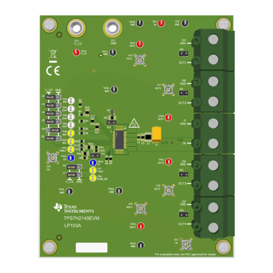
TPS7H2140EVM Board
Copyright © 2023 Texas Instruments Incorporated
TPS7H2140-SEP Evaluation Module (EVM)
Description
1
Advertisement
Table of Contents

Related Manuals for Texas Instruments TPS7H2140-SEP


Summary of Contents for Texas Instruments TPS7H2140-SEP
- Page 1 1. Operating voltage 4.5 V– 32 V demonstrate the operation and features of the 2. Programmable current limit with external resistor TPS7H2140-SEP eFuse. The EVM provides test 3. Output channels can be connected in parallel for points, jumpers, connection terminals, and labeled...
-
Page 2: Kit Contents
EVM is configured as shown in Table 1-1. To change the configuration of the device, please refer to the TPS7H2140-SEP data sheet (SLVSH46) to calculate values of any passive components that need to be changed. 1.2 Kit Contents •... -
Page 3: Device Information
R29 = 442 Ω 1.4 Device Information The TPS7H2140-SEP is a quad-channel, 4.5 V to 32 V, 160-mΩ eFuse with an adjustable current limit and high accuracy current sense. Additionally, the TPS7H2140-SEP features short-to-GND protection, loss-of-GND protection, thermal overload protection, and inductive load negative voltage clamp. The device contains four N-channel MOSFETs for independent control of all four channels using a discrete enable signal for each output channel. - Page 4 This section describes the connectors on the EVM as well and how to properly connect, set up, and use the TPS7H2140EVM. 2.1.1 Connectors TPS7H2140EVM TPS7H2140-SEP Evaluation Module (EVM) SLVUCS1A – JULY 2023 – REVISED AUGUST 2023 Submit Document Feedback Copyright © 2023 Texas Instruments Incorporated...
- Page 5 GND - GND_IC Open-load detection pull-up OUT1 Open-load detection pull-up OUT2 Open-load detection pull-up OUT3 Open-load detection pull-up OUT4 SLVUCS1A – JULY 2023 – REVISED AUGUST 2023 TPS7H2140-SEP Evaluation Module (EVM) Submit Document Feedback Copyright © 2023 Texas Instruments Incorporated...
- Page 6 CS pin (I ). Check R with Equation CS_FAULT V CS_FAULT MAX V CS ≥ I CS I CS_FAULT MIN TPS7H2140-SEP Evaluation Module (EVM) SLVUCS1A – JULY 2023 – REVISED AUGUST 2023 Submit Document Feedback Copyright © 2023 Texas Instruments Incorporated...
- Page 7 TPS7H2140EVM with less than all four channels being loaded, the shunts for each disabled and unloaded channel must be removed for the FAULT pin to report accurately. SLVUCS1A – JULY 2023 – REVISED AUGUST 2023 TPS7H2140-SEP Evaluation Module (EVM) Submit Document Feedback Copyright © 2023 Texas Instruments Incorporated...
- Page 8 Remove the other enable jumpers for the bonded channel set. TPS7H2140-SEP Evaluation Module (EVM) SLVUCS1A – JULY 2023 – REVISED AUGUST 2023 Submit Document Feedback Copyright © 2023 Texas Instruments Incorporated...
-
Page 9: Power Up And Power Down
Figure 3-1. Power-up Figure 3-2. Power-down Both tests were performed using VIN = 12 V and a load of 12 Ω. SLVUCS1A – JULY 2023 – REVISED AUGUST 2023 TPS7H2140-SEP Evaluation Module (EVM) Submit Document Feedback Copyright © 2023 Texas Instruments Incorporated... -
Page 10: Enable And Disable
Figure 3-4. Channel Disable Both tests were performed using VIN = 12 V and a load of 12 Ω. TPS7H2140-SEP Evaluation Module (EVM) SLVUCS1A – JULY 2023 – REVISED AUGUST 2023 Submit Document Feedback Copyright © 2023 Texas Instruments Incorporated... - Page 11 The cross-channel load step test was performed using VIN = 12 V, and a load step from 48 Ω to 12 Ω on CH1. Voltage measurements for CH2-CH4 were made using AC coupling mode. SLVUCS1A – JULY 2023 – REVISED AUGUST 2023 TPS7H2140-SEP Evaluation Module (EVM) Submit Document Feedback Copyright © 2023 Texas Instruments Incorporated...
-
Page 12: Overcurrent Protection
Load Both tests were performed using VIN = 12 V, and a load between 6 Ω and 12 Ω. TPS7H2140-SEP Evaluation Module (EVM) SLVUCS1A – JULY 2023 – REVISED AUGUST 2023 Submit Document Feedback Copyright © 2023 Texas Instruments Incorporated... - Page 13 The following test was performed with an EVM board that was modified by removing the output capacitors, and is meant to demonstrate the fast-trip overcurrent protection of the TPS7H2140-SEP. For the purposes of demonstrating the fast-trip feature, the output of the device was short-circuited to collect Figure 3-9.
- Page 14 Hardware Design Files www.ti.com 4 Hardware Design Files 4.1 Schematic Figure 4-1. TPS7H2140EVM Schematic TPS7H2140-SEP Evaluation Module (EVM) SLVUCS1A – JULY 2023 – REVISED AUGUST 2023 Submit Document Feedback Copyright © 2023 Texas Instruments Incorporated...
-
Page 15: Pcb Layouts
The EVM board utilizes a GND network to allow for testing of applications that can require one. However, if a GND network is not required for the application of the TPS7H2140-SEP, the thermal pad can also be connected directly to a GND plane to improve thermal performance. Additional information can be found in... - Page 16 Hardware Design Files www.ti.com Figure 4-3. Top Solder Mask TPS7H2140-SEP Evaluation Module (EVM) SLVUCS1A – JULY 2023 – REVISED AUGUST 2023 Submit Document Feedback Copyright © 2023 Texas Instruments Incorporated...
- Page 17 Hardware Design Files Figure 4-4. Layer 1 (Top) SLVUCS1A – JULY 2023 – REVISED AUGUST 2023 TPS7H2140-SEP Evaluation Module (EVM) Submit Document Feedback Copyright © 2023 Texas Instruments Incorporated...
- Page 18 Hardware Design Files www.ti.com Figure 4-5. Layer 2 TPS7H2140-SEP Evaluation Module (EVM) SLVUCS1A – JULY 2023 – REVISED AUGUST 2023 Submit Document Feedback Copyright © 2023 Texas Instruments Incorporated...
- Page 19 Hardware Design Files Figure 4-6. Layer 2 SLVUCS1A – JULY 2023 – REVISED AUGUST 2023 TPS7H2140-SEP Evaluation Module (EVM) Submit Document Feedback Copyright © 2023 Texas Instruments Incorporated...
- Page 20 Hardware Design Files www.ti.com Figure 4-7. Layer 3 (Bottom) TPS7H2140-SEP Evaluation Module (EVM) SLVUCS1A – JULY 2023 – REVISED AUGUST 2023 Submit Document Feedback Copyright © 2023 Texas Instruments Incorporated...
- Page 21 Hardware Design Files Figure 4-8. Bottom Solder Mask SLVUCS1A – JULY 2023 – REVISED AUGUST 2023 TPS7H2140-SEP Evaluation Module (EVM) Submit Document Feedback Copyright © 2023 Texas Instruments Incorporated...
- Page 22 Hardware Design Files www.ti.com Figure 4-9. Bottom Overlay TPS7H2140-SEP Evaluation Module (EVM) SLVUCS1A – JULY 2023 – REVISED AUGUST 2023 Submit Document Feedback Copyright © 2023 Texas Instruments Incorporated...
-
Page 23: Bill Of Materials
0805 RT0805BRD07442RL Yageo America 0805 RES, 1.00 k, 1%, 0.125 W, 1.00k 0805 CRCW08051K00FKEA Vishay-Dale AEC-Q200 Grade 0, 0805 SLVUCS1A – JULY 2023 – REVISED AUGUST 2023 TPS7H2140-SEP Evaluation Module (EVM) Submit Document Feedback Copyright © 2023 Texas Instruments Incorporated... - Page 24 Radiation Tolerant 32-V, 160- Texas HTSSOP28 TPS7H2140MPWPTSEP mΩ Quad-Channel eFuse Instruments High-Voltage Ultralow-I(q) Texas Low-Dropout Regulator, DGN0008D TPS7A6650QDGNRQ1 Instruments DGN0008D (HVSSOP-8) TPS7H2140-SEP Evaluation Module (EVM) SLVUCS1A – JULY 2023 – REVISED AUGUST 2023 Submit Document Feedback Copyright © 2023 Texas Instruments Incorporated...
-
Page 25: Revision History
Changes from Revision * (July 2023) to Revision A (August 2023) Page • Changeded input voltage range throughout document..................• Changed description of EVM configuration used for implementation results............. SLVUCS1A – JULY 2023 – REVISED AUGUST 2023 TPS7H2140-SEP Evaluation Module (EVM) Submit Document Feedback Copyright © 2023 Texas Instruments Incorporated... - Page 26 STANDARD TERMS FOR EVALUATION MODULES Delivery: TI delivers TI evaluation boards, kits, or modules, including any accompanying demonstration software, components, and/or documentation which may be provided together or separately (collectively, an “EVM” or “EVMs”) to the User (“User”) in accordance with the terms set forth herein.
- Page 27 www.ti.com Regulatory Notices: 3.1 United States 3.1.1 Notice applicable to EVMs not FCC-Approved: FCC NOTICE: This kit is designed to allow product developers to evaluate electronic components, circuitry, or software associated with the kit to determine whether to incorporate such items in a finished product and software developers to write software applications for use with the end product.
- Page 28 www.ti.com Concernant les EVMs avec antennes détachables Conformément à la réglementation d'Industrie Canada, le présent émetteur radio peut fonctionner avec une antenne d'un type et d'un gain maximal (ou inférieur) approuvé pour l'émetteur par Industrie Canada. Dans le but de réduire les risques de brouillage radioélectrique à...
- Page 29 www.ti.com EVM Use Restrictions and Warnings: 4.1 EVMS ARE NOT FOR USE IN FUNCTIONAL SAFETY AND/OR SAFETY CRITICAL EVALUATIONS, INCLUDING BUT NOT LIMITED TO EVALUATIONS OF LIFE SUPPORT APPLICATIONS. 4.2 User must read and apply the user guide and other available documentation provided by TI regarding the EVM prior to handling or using the EVM, including without limitation any warning or restriction notices.
- Page 30 Notwithstanding the foregoing, any judgment may be enforced in any United States or foreign court, and TI may seek injunctive relief in any United States or foreign court. Mailing Address: Texas Instruments, Post Office Box 655303, Dallas, Texas 75265 Copyright © 2023, Texas Instruments Incorporated...
- Page 31 TI products. TI’s provision of these resources does not expand or otherwise alter TI’s applicable warranties or warranty disclaimers for TI products. TI objects to and rejects any additional or different terms you may have proposed. IMPORTANT NOTICE Mailing Address: Texas Instruments, Post Office Box 655303, Dallas, Texas 75265 Copyright © 2023, Texas Instruments Incorporated...
Need help?
Do you have a question about the TPS7H2140-SEP and is the answer not in the manual?
Questions and answers