Advertisement
Quick Links
www.ti.com
EVM User's Guide: TPS7H2211EVM TPS7H2211-SEP
TPS7H2211EVM Evaluation Module (EVM)
Description
The TPS7H2211EVM demonstrates the operation
of a single TPS7H2211 eFuse (Radiation Tolerant/
Hardened Plastic). The board provides footprints that
can be populated with additional components to allow
for testing of customized configurations, such as
parallel or redundant eFuses.
The EVM is populated for a single-device configuration. The footprints on the bottom half of the board can be populated if a parallel-
device configuration is desired.
SLVUCQ6 – JULY 2023
Submit Document Feedback
Features
•
Flexible configuration options, including single-
and parallel-device circuits
•
Customizable soft start, enable threshold,
undervoltage threshold, and capacitance
TPS7H2211EVM Board
Copyright © 2023 Texas Instruments Incorporated
TPS7H2211EVM Evaluation Module (EVM)
Description
1
Advertisement

Related Manuals for Texas Instruments TPS7H2211EVM


Summary of Contents for Texas Instruments TPS7H2211EVM
- Page 1 Description EVM User's Guide: TPS7H2211EVM TPS7H2211-SEP TPS7H2211EVM Evaluation Module (EVM) Description Features The TPS7H2211EVM demonstrates the operation • Flexible configuration options, including single- of a single TPS7H2211 eFuse (Radiation Tolerant/ and parallel-device circuits Hardened Plastic). The board provides footprints that •...
-
Page 2: Kit Contents
1 Evaluation Module Overview 1.1 Introduction The TPS7H2211EVM is the Evaluation Module (EVM) for the plastic package option of the TPS7H2211 and provides a platform to electrically evaluate the features. This user’s guide provides details about the EVM, including the configuration, schematics, and BOM. -
Page 3: Device Information
In addition to the default EVM configuration, this user's guide provides an example for how the TPS7H2211EVM can be configured for parallel operation. The enable (EN) and overvoltage protection (OVP) specifications for the parallel configuration are the same as what is used for the default configuration. -
Page 4: Evm Connectors And Test Points
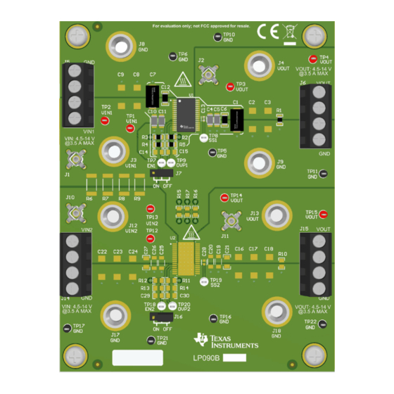
Hardware www.ti.com 2 Hardware 2.1 EVM Connectors and Test Points Figure 2-1. TPS7H2211EVM 3D Rendering (Top) Table 2-1. Summary of Connectors and Test Points Reference Designator Function J3, J5 (pins 3 & 4) VIN1 Input Voltage and Current for U1 J8, J5 (pins 1 &... - Page 5 J2, J11, TP3, TP4, TP14, TP15 TP5, TP6, TP10, TP11, TP16, TP17, TP21, TP22 Test Point TP19 TP18 OVP1 TP20 OVP2 VIN1-EN1-GND Shunt for mode selection VIN2-EN2-GND SLVUCQ6 – JULY 2023 TPS7H2211EVM Evaluation Module (EVM) Submit Document Feedback Copyright © 2023 Texas Instruments Incorporated...
- Page 6 3.1 Default Configuration Results The results shown in Figure 3-1 through Figure 3-4 were observed using the TPS7H2211EVM in the default configuration with VIN = 12 V. Figure 3-1. Default Configuration: Start Up Figure 3-2. Default Configuration: Shutdown TPS7H2211EVM Evaluation Module (EVM) SLVUCQ6 –...
- Page 7 Implementation Results Figure 3-3. Default Configuration: Assertion of OVP Due to Input Voltage Figure 3-4. Default Configuration: Deassertion of OVP Due to Input Voltage SLVUCQ6 – JULY 2023 TPS7H2211EVM Evaluation Module (EVM) Submit Document Feedback Copyright © 2023 Texas Instruments Incorporated...
- Page 8 The results shown in Figure 3-5 through Figure 3-8 were observed using the TPS7H2211EVM in the parallel configuration shown in this document with VIN = 13 V. Figure 3-5. Parallel Configuration: Start Up Figure 3-6. Parallel Configuration: Shutdown TPS7H2211EVM Evaluation Module (EVM) SLVUCQ6 –...
- Page 9 Implementation Results Figure 3-7. Parallel Configuration: Assertion of OVP due to Input Voltage Figure 3-8. Parallel Configuration: Deassertion of OVP due to Input Voltage SLVUCQ6 – JULY 2023 TPS7H2211EVM Evaluation Module (EVM) Submit Document Feedback Copyright © 2023 Texas Instruments Incorporated...
- Page 10 Hardware Design Files www.ti.com 4 Hardware Design Files 4.1 Schematic Figure 4-1 shows the default TPS7H2211EVM schematic. Figure 4-2 is the schematic for the parallel configuration of the EVM shown in this document. (4.5V-14V) VIN1 VOUT VOUT VOUT VOUT VOUT VOUT 10.0k...
- Page 11 OVP_2 TP20 9.31k 0.1uF OVP_2 TP21 9.31k 0.1uF Thermal_Pad TP22 EN_1 SS_1 TPS7H2211MDAPTSEP EN_2 SS_2 OVP_1 OVP_2 Figure 4-2. Example: TPS7H2211EVM Parallel Schematic SLVUCQ6 – JULY 2023 TPS7H2211EVM Evaluation Module (EVM) Submit Document Feedback Copyright © 2023 Texas Instruments Incorporated...
-
Page 12: Board Layout
Hardware Design Files www.ti.com 4.2 Board Layout Figure 4-3 through Figure 4-9 show the layout of the TPS7H2211EVM. Figure 4-3. Top Overlay TPS7H2211EVM Evaluation Module (EVM) SLVUCQ6 – JULY 2023 Submit Document Feedback Copyright © 2023 Texas Instruments Incorporated... - Page 13 Hardware Design Files Figure 4-4. Top Solder Mask SLVUCQ6 – JULY 2023 TPS7H2211EVM Evaluation Module (EVM) Submit Document Feedback Copyright © 2023 Texas Instruments Incorporated...
- Page 14 Hardware Design Files www.ti.com Figure 4-5. Layer 1 (Top) TPS7H2211EVM Evaluation Module (EVM) SLVUCQ6 – JULY 2023 Submit Document Feedback Copyright © 2023 Texas Instruments Incorporated...
- Page 15 Hardware Design Files Figure 4-6. Layer 2 SLVUCQ6 – JULY 2023 TPS7H2211EVM Evaluation Module (EVM) Submit Document Feedback Copyright © 2023 Texas Instruments Incorporated...
- Page 16 Hardware Design Files www.ti.com Figure 4-7. Layer 3-7 TPS7H2211EVM Evaluation Module (EVM) SLVUCQ6 – JULY 2023 Submit Document Feedback Copyright © 2023 Texas Instruments Incorporated...
- Page 17 Hardware Design Files Figure 4-8. Layer 8 (Bottom) SLVUCQ6 – JULY 2023 TPS7H2211EVM Evaluation Module (EVM) Submit Document Feedback Copyright © 2023 Texas Instruments Incorporated...
- Page 18 Hardware Design Files www.ti.com Figure 4-9. Bottom Solder TPS7H2211EVM Evaluation Module (EVM) SLVUCQ6 – JULY 2023 Submit Document Feedback Copyright © 2023 Texas Instruments Incorporated...
- Page 19 BOM for the default EVM configuration. Parallel Configuration Bill of Materials (BOM) lists the BOM for the parallel configuration of the EVM shown in this document. Default Configuration Bill of Materials (BOM) Table 4-1. TPS7H2211EVM Default Bill of Materials (BOM) Designator Quantity Value Description...
- Page 20 Hardware Design Files www.ti.com Table 4-1. TPS7H2211EVM Default Bill of Materials (BOM) (continued) Designator Quantity Value Description PackageReference PartNumber Manufacturer 150 µF Molded Tantalum Polymer C2, C3, C8, C9, C16, C17, Capacitor 20 V 2917 (7343 Metric) 2917 T521D157M020ATE050 Kemet...
- Page 21 Hardware Design Files Parallel Configuration Bill of Materials (BOM) An example BOM for the EVM configured for parallel operation is provided below. Table 4-2. Example: TPS7H2211EVM Parallel Bill of Materials (BOM Designator Quantity Value Description PackageReference PartNumber Manufacturer 150 µF Molded Tantalum Polymer...
- Page 22 Hardware Design Files www.ti.com Table 4-2. Example: TPS7H2211EVM Parallel Bill of Materials (BOM (continued) Designator Quantity Value Description PackageReference PartNumber Manufacturer Radiation-Hardness-Assured (RHA) 14-V, U1, U2 TSSOP32 TPS7H2211MDAPTSEP Texas Instruments 3.5-A eFuse 150 µF Molded Tantalum Polymer C2, C3, C8, C9, C17, C18,...
-
Page 23: Related Documentation
Related Documentation 5 Related Documentation • Texas Instruments, Standard Terms for Evaluation Modules SLVUCQ6 – JULY 2023 TPS7H2211EVM Evaluation Module (EVM) Submit Document Feedback Copyright © 2023 Texas Instruments Incorporated... - Page 24 STANDARD TERMS FOR EVALUATION MODULES Delivery: TI delivers TI evaluation boards, kits, or modules, including any accompanying demonstration software, components, and/or documentation which may be provided together or separately (collectively, an “EVM” or “EVMs”) to the User (“User”) in accordance with the terms set forth herein.
- Page 25 www.ti.com Regulatory Notices: 3.1 United States 3.1.1 Notice applicable to EVMs not FCC-Approved: FCC NOTICE: This kit is designed to allow product developers to evaluate electronic components, circuitry, or software associated with the kit to determine whether to incorporate such items in a finished product and software developers to write software applications for use with the end product.
- Page 26 www.ti.com Concernant les EVMs avec antennes détachables Conformément à la réglementation d'Industrie Canada, le présent émetteur radio peut fonctionner avec une antenne d'un type et d'un gain maximal (ou inférieur) approuvé pour l'émetteur par Industrie Canada. Dans le but de réduire les risques de brouillage radioélectrique à...
- Page 27 www.ti.com EVM Use Restrictions and Warnings: 4.1 EVMS ARE NOT FOR USE IN FUNCTIONAL SAFETY AND/OR SAFETY CRITICAL EVALUATIONS, INCLUDING BUT NOT LIMITED TO EVALUATIONS OF LIFE SUPPORT APPLICATIONS. 4.2 User must read and apply the user guide and other available documentation provided by TI regarding the EVM prior to handling or using the EVM, including without limitation any warning or restriction notices.
- Page 28 Notwithstanding the foregoing, any judgment may be enforced in any United States or foreign court, and TI may seek injunctive relief in any United States or foreign court. Mailing Address: Texas Instruments, Post Office Box 655303, Dallas, Texas 75265 Copyright © 2023, Texas Instruments Incorporated...
- Page 29 TI products. TI’s provision of these resources does not expand or otherwise alter TI’s applicable warranties or warranty disclaimers for TI products. TI objects to and rejects any additional or different terms you may have proposed. IMPORTANT NOTICE Mailing Address: Texas Instruments, Post Office Box 655303, Dallas, Texas 75265 Copyright © 2023, Texas Instruments Incorporated...
Need help?
Do you have a question about the TPS7H2211EVM and is the answer not in the manual?
Questions and answers