Table of Contents
Advertisement
Quick Links
www.ti.com
User's Guide
TPS7H1111EVM-CVAL Evaluation Module (EVM)
This user's guide describes operational use of the TPS7H1111EVM-CVAL evaluation module (EVM) as a
reference design for engineering demonstration and evaluation of the TPS7H1111-SP, a 1.5-A, Ultra-Low Noise,
High PSRR, Radiation-Hardness-Assured RF Low Drop Out (LDO) regulator. This user's guide provides details
about the EVM, its configuration, schematics, and bill of material (BOM).
1
Introduction.............................................................................................................................................................................2
Information............................................................................................................................................................3
1.2 Features.............................................................................................................................................................................
1.3
Applications........................................................................................................................................................................3
2
Setup........................................................................................................................................................................................4
2.1 Input/Output Connectors and Jumper Descriptions...........................................................................................................
Setup................................................................................................................................................................6
3
Operation.................................................................................................................................................................................6
Operation..............................................................................................................................................................7
Results.............................................................................................................................................................................8
5.1 Enable and Soft Start Timing.............................................................................................................................................
5.2 PSRR.................................................................................................................................................................................
5.3
Stability.............................................................................................................................................................................10
5.4 Noise Spectral Density.....................................................................................................................................................
Layout.........................................................................................................................................................................12
7
Schematic..............................................................................................................................................................................16
8 Bill of Materials.....................................................................................................................................................................
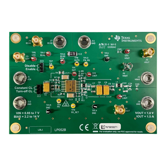
Figure 1-1. TPS7H1111EVM-CVAL (LP052B).............................................................................................................................
Figure 5-1. TPS7H1111 enable and soft start timing...................................................................................................................
Figure 5-3. TPS7H1111EVM-CVAL Gain and Phase vs. Frequency (Bode Plot)......................................................................
Figure 5-4. Output Noise vs. Frequency across Output Current (Noise Spectral Density)........................................................
Silkscreen............................................................................................................................................12
Mask......................................................................................................................................................12
Layer......................................................................................................................................................13
Figure 6-4. Signal 1 Layer.........................................................................................................................................................
Figure 6-5. Signal 2 Layer.........................................................................................................................................................
Figure 6-6. Bottom Signal Layer................................................................................................................................................
Layer................................................................................................................................................15
Table 2-1. Jumpers......................................................................................................................................................................
Table 2-2. Test Points..................................................................................................................................................................
Materials..........................................................................................................................................................17
Trademarks
All trademarks are the property of their respective owners.
SLVUCG5 - JANUARY 2023
Submit Document Feedback
ABSTRACT
Table of Contents
List of Figures
Voltage....................................................................................................7
.....................................................................................................................
Schematic..........................................................................................................16
List of Tables
Copyright © 2023 Texas Instruments Incorporated
TPS7H1111EVM-CVAL Evaluation Module (EVM)
Table of Contents
3
4
8
9
11
17
2
8
9
10
11
13
14
14
4
5
1
Advertisement
Table of Contents

Related Manuals for Texas Instruments TPS7H1111EVM-CVAL


Summary of Contents for Texas Instruments TPS7H1111EVM-CVAL
-
Page 1: Table Of Contents
TPS7H1111EVM-CVAL Evaluation Module (EVM) ABSTRACT This user’s guide describes operational use of the TPS7H1111EVM-CVAL evaluation module (EVM) as a reference design for engineering demonstration and evaluation of the TPS7H1111-SP, a 1.5-A, Ultra-Low Noise, High PSRR, Radiation-Hardness-Assured RF Low Drop Out (LDO) regulator. This user's guide provides details about the EVM, its configuration, schematics, and bill of material (BOM). -
Page 2: Introduction
1.5 A to a load. Achieving the maximum load depends on multiple variables, including the input-output power dissipation, board thermal dissipation, and heat removal. Figure 1-1. TPS7H1111EVM-CVAL (LP052B) TPS7H1111EVM-CVAL Evaluation Module (EVM) SLVUCG5 – JANUARY 2023 Submit Document Feedback Copyright © 2023 Texas Instruments Incorporated... -
Page 3: Related Information
• Accurate supply for FPGAs (field programmable gate arrays) and DSPs (digital signal processors) • Radiation-hardened ultra-clean analog supply for space constrained areas SLVUCG5 – JANUARY 2023 TPS7H1111EVM-CVAL Evaluation Module (EVM) Submit Document Feedback Copyright © 2023 Texas Instruments Incorporated... -
Page 4: Setup
Three pin enable/disable jumper selector. Pulls EN signal to V "enable" or GND "disable". No jumper will enable LDO based on V R2/R7 divider reaching 600mV enable threshold. TPS7H1111EVM-CVAL Evaluation Module (EVM) SLVUCG5 – JANUARY 2023 Submit Document Feedback Copyright © 2023 Texas Instruments Incorporated... -
Page 5: Table 2-2. Test Points
Bias test point, located on source side of the bias filter defined by R6 and C14. TP13 FB_PG test point. TP14, TP15 GND test points. SLVUCG5 – JANUARY 2023 TPS7H1111EVM-CVAL Evaluation Module (EVM) Submit Document Feedback Copyright © 2023 Texas Instruments Incorporated... -
Page 6: Equipment Setup
Setup www.ti.com 2.2 Equipment Setup The following procedure guides the setup and testing of the TPS7H1111EVM-CVAL. The following equipment is required for this testing: 1. Power supply PS1 capable of up to 7 V and 1.5 A for suppling V •... -
Page 7: Adjustable Operation
Thus, setting appropriate divider is important for proper startup. See SLVSFT8 for more detailed information. SLVUCG5 – JANUARY 2023 TPS7H1111EVM-CVAL Evaluation Module (EVM) Submit Document Feedback Copyright © 2023 Texas Instruments Incorporated... -
Page 8: Test Results
5 Test Results This section provides typical performance waveforms for the TPS7H1111EVM-CVAL with respect to stability, Noise Spectral Density (NSD), and PSRR. All performance data show is utilizing the the standard configuration of the EVM. The standard configuration is based on the following conditions: Vin = 2.5 V, Vbias = 5 V, and Vout = 1.8 V... -
Page 9: Psrr
Test Results 5.2 PSRR Figure 5-2 shows the typical PSRR performance of the TPS7H1111EVM-CVAL at various I loads under the following conditions: V = 2.5 V, V = 5 V, V = 1.8 V, C removed. BIAS = 1.5 A... -
Page 10: Stability
Figure 5-3 shows the typical Bode gain and phase plot versus frequency for minimum no load, and maximum load of 1.5 A. Stability tests performed with the TPS7H1111EVM-CVAL operating with the following conditions: = 2.5 V, V = 5 V, V = 1.8 V. -
Page 11: Noise Spectral Density
Test Results 5.4 Noise Spectral Density Figure 5-4 shows the typical Noise Spectral Density (NSD) performance of the TPS7H1111EVM-CVAL operating with the following conditions: V = 2.5 V, V = 5 V, V = 1.8 V. The plot also shows the integrated 10 Hz to BIAS 100 kHz RMS noise for the various output loads. -
Page 12: Board Layout
Board Layout www.ti.com 6 Board Layout The following images represent the board design layers. Figure 6-1. Top Overlay Silkscreen Figure 6-2. Top Solder Mask TPS7H1111EVM-CVAL Evaluation Module (EVM) SLVUCG5 – JANUARY 2023 Submit Document Feedback Copyright © 2023 Texas Instruments Incorporated... -
Page 13: Figure 6-3. Top Signal Layer
Board Layout Figure 6-3. Top Signal Layer Figure 6-4. Signal 1 Layer SLVUCG5 – JANUARY 2023 TPS7H1111EVM-CVAL Evaluation Module (EVM) Submit Document Feedback Copyright © 2023 Texas Instruments Incorporated... -
Page 14: Figure 6-5. Signal 2 Layer
Board Layout www.ti.com Figure 6-5. Signal 2 Layer Figure 6-6. Bottom Signal Layer TPS7H1111EVM-CVAL Evaluation Module (EVM) SLVUCG5 – JANUARY 2023 Submit Document Feedback Copyright © 2023 Texas Instruments Incorporated... -
Page 15: Figure 6-7. Bottom Solder Layer
Board Layout Figure 6-7. Bottom Solder Layer SLVUCG5 – JANUARY 2023 TPS7H1111EVM-CVAL Evaluation Module (EVM) Submit Document Feedback Copyright © 2023 Texas Instruments Incorporated... -
Page 16: Schematic
Not in version control Assembly Variant: Sheet: warrant that this design will meet the specifications, will be suitable for your application or fit for any particular purpose, or will operate in an implementation. Texas Instruments and/or its Drawn By: Wade Vonbergen File: LP052B.SchDoc... -
Page 17: Bill Of Materials
Capacitor, ceramic, 6.8 μF, 50 V, ± 10%, X7R, AEC-Q200 CGA8P3X7R1H685K250KB Grade 1, Capacitor, ceramic, 0.01 μF, 16 V, ±5%, C0G/NP0, 0805 B37947K9103J62 SLVUCG5 – JANUARY 2023 TPS7H1111EVM-CVAL Evaluation Module (EVM) Submit Document Feedback Copyright © 2023 Texas Instruments Incorporated... - Page 18 STANDARD TERMS FOR EVALUATION MODULES Delivery: TI delivers TI evaluation boards, kits, or modules, including any accompanying demonstration software, components, and/or documentation which may be provided together or separately (collectively, an “EVM” or “EVMs”) to the User (“User”) in accordance with the terms set forth herein.
- Page 19 www.ti.com Regulatory Notices: 3.1 United States 3.1.1 Notice applicable to EVMs not FCC-Approved: FCC NOTICE: This kit is designed to allow product developers to evaluate electronic components, circuitry, or software associated with the kit to determine whether to incorporate such items in a finished product and software developers to write software applications for use with the end product.
- Page 20 www.ti.com Concernant les EVMs avec antennes détachables Conformément à la réglementation d'Industrie Canada, le présent émetteur radio peut fonctionner avec une antenne d'un type et d'un gain maximal (ou inférieur) approuvé pour l'émetteur par Industrie Canada. Dans le but de réduire les risques de brouillage radioélectrique à...
- Page 21 www.ti.com EVM Use Restrictions and Warnings: 4.1 EVMS ARE NOT FOR USE IN FUNCTIONAL SAFETY AND/OR SAFETY CRITICAL EVALUATIONS, INCLUDING BUT NOT LIMITED TO EVALUATIONS OF LIFE SUPPORT APPLICATIONS. 4.2 User must read and apply the user guide and other available documentation provided by TI regarding the EVM prior to handling or using the EVM, including without limitation any warning or restriction notices.
- Page 22 Notwithstanding the foregoing, any judgment may be enforced in any United States or foreign court, and TI may seek injunctive relief in any United States or foreign court. Mailing Address: Texas Instruments, Post Office Box 655303, Dallas, Texas 75265 Copyright © 2023, Texas Instruments Incorporated...
- Page 23 TI products. TI’s provision of these resources does not expand or otherwise alter TI’s applicable warranties or warranty disclaimers for TI products. TI objects to and rejects any additional or different terms you may have proposed. IMPORTANT NOTICE Mailing Address: Texas Instruments, Post Office Box 655303, Dallas, Texas 75265 Copyright © 2023, Texas Instruments Incorporated...
Need help?
Do you have a question about the TPS7H1111EVM-CVAL and is the answer not in the manual?
Questions and answers