Table of Contents
Advertisement
Quick Links
www.ti.com
User's Guide
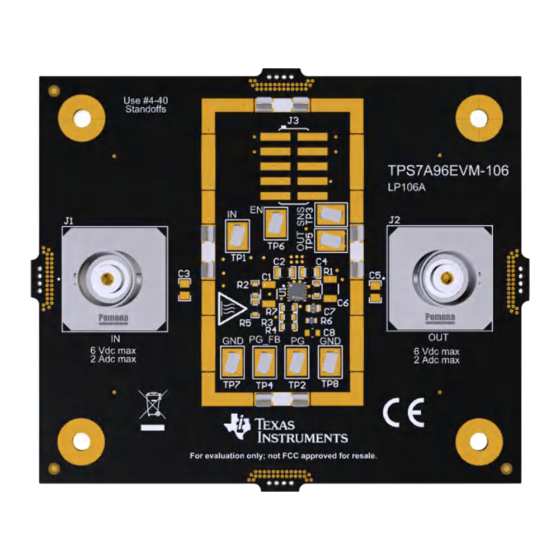
TPS7A96EVM-106 Evaluation Module
This user's guide describes the operational use of the TPS7A96EVM-106 evaluation module (EVM) as a
reference design for engineering demonstration and evaluation of the TPS7A9601DSC, an ultra-low noise,
ultra-high PSRR, RF low-dropout (LDO) linear regulator. Included in this user's guide are setup and operating
instructions, thermal and layout guidelines, a printed circuit board (PCB) layout, a schematic diagram, and a bill
of materials (BOM).
Throughout this document the terms demonstration kit, evaluation board, and evaluation module are
synonymous with the TPS7A96EVM-106.
SBVU081 – JUNE 2023
Submit Document Feedback
ABSTRACT
Figure 1-1. TPS7A96EVM-106 Evaluation Module
Copyright © 2023 Texas Instruments Incorporated
TPS7A96EVM-106 Evaluation Module
1
Advertisement
Table of Contents

Related Manuals for Texas Instruments TPS7A96EVM-106


Summary of Contents for Texas Instruments TPS7A96EVM-106
- Page 1 ABSTRACT Figure 1-1. TPS7A96EVM-106 Evaluation Module This user's guide describes the operational use of the TPS7A96EVM-106 evaluation module (EVM) as a reference design for engineering demonstration and evaluation of the TPS7A9601DSC, an ultra-low noise, ultra-high PSRR, RF low-dropout (LDO) linear regulator. Included in this user's guide are setup and operating instructions, thermal and layout guidelines, a printed circuit board (PCB) layout, a schematic diagram, and a bill of materials (BOM).
-
Page 2: Table Of Contents
2.3 Equipment Connections..............................Operation....................................4 Schematic....................................5 5 PCB Layout....................................6 6 Bill of Materials..................................List of Figures Figure 1-1. TPS7A96EVM-106 Evaluation Module........................Figure 4-1. TPS7A96EVM-106 Schematic..........................Figure 5-1. Assembly Layer.................................6 Figure 5-2. Top Layer Routing..............................Figure 5-3. First Middle Layer..............................6 Figure 5-4. Second Middle Layer..............................6... -
Page 3: Introduction
Introduction 1 Introduction Texas Instruments' TPS7A96EVM-106 helps design engineers evaluate the operation and performance of the TPS7A96 linear regulator for possible use in their own circuit application. This particular EVM configuration contains a single high-accuracy, small size, adjustable linear regulator for a wide range of applications. The... -
Page 4: Evm Setup
EVM Setup www.ti.com 2 EVM Setup This section describes how to properly connect and set up the TPS7A96EVM-106, including the jumpers and connectors on the EVM board. 2.1 Inputs/Outputs Connectors and Jumper Descriptions 2.1.1 J1 – IN Input power-supply voltage connector with ground connection. -
Page 5: Schematic
PG_FB FB_PG MNT_4 MNT_4 10µF 10µF 10µF 10µF 10uF 10uF NR/SS NR/SS Thermal_Pad TPS7A9601DSCR 4.7µF 4.7µF 10.0k 12.4k NR/SS PG_FB Figure 4-1. TPS7A96EVM-106 Schematic SBVU081 – JUNE 2023 TPS7A96EVM-106 Evaluation Module Submit Document Feedback Copyright © 2023 Texas Instruments Incorporated... -
Page 6: Pcb Layout
PCB layout for this EVM. Figure 5-1. Assembly Layer Figure 5-2. Top Layer Routing Figure 5-3. First Middle Layer Figure 5-4. Second Middle Layer TPS7A96EVM-106 Evaluation Module SBVU081 – JUNE 2023 Submit Document Feedback Copyright © 2023 Texas Instruments Incorporated... -
Page 7: Figure 5-5. Bottom Layer
PCB Layout Figure 5-5. Bottom Layer Routing SBVU081 – JUNE 2023 TPS7A96EVM-106 Evaluation Module Submit Document Feedback Copyright © 2023 Texas Instruments Incorporated... -
Page 8: Bill Of Materials
This assembly must comply with workmanship standards IPC-A-610 Class 2. Unless otherwise noted in the Alternate Part Number or Alternate Manufacturer columns, all parts can be substituted with equivalents. TPS7A96EVM-106 Evaluation Module SBVU081 – JUNE 2023 Submit Document Feedback Copyright © 2023 Texas Instruments Incorporated... - Page 9 STANDARD TERMS FOR EVALUATION MODULES Delivery: TI delivers TI evaluation boards, kits, or modules, including any accompanying demonstration software, components, and/or documentation which may be provided together or separately (collectively, an “EVM” or “EVMs”) to the User (“User”) in accordance with the terms set forth herein.
- Page 10 www.ti.com Regulatory Notices: 3.1 United States 3.1.1 Notice applicable to EVMs not FCC-Approved: FCC NOTICE: This kit is designed to allow product developers to evaluate electronic components, circuitry, or software associated with the kit to determine whether to incorporate such items in a finished product and software developers to write software applications for use with the end product.
- Page 11 www.ti.com Concernant les EVMs avec antennes détachables Conformément à la réglementation d'Industrie Canada, le présent émetteur radio peut fonctionner avec une antenne d'un type et d'un gain maximal (ou inférieur) approuvé pour l'émetteur par Industrie Canada. Dans le but de réduire les risques de brouillage radioélectrique à...
- Page 12 www.ti.com EVM Use Restrictions and Warnings: 4.1 EVMS ARE NOT FOR USE IN FUNCTIONAL SAFETY AND/OR SAFETY CRITICAL EVALUATIONS, INCLUDING BUT NOT LIMITED TO EVALUATIONS OF LIFE SUPPORT APPLICATIONS. 4.2 User must read and apply the user guide and other available documentation provided by TI regarding the EVM prior to handling or using the EVM, including without limitation any warning or restriction notices.
- Page 13 Notwithstanding the foregoing, any judgment may be enforced in any United States or foreign court, and TI may seek injunctive relief in any United States or foreign court. Mailing Address: Texas Instruments, Post Office Box 655303, Dallas, Texas 75265 Copyright © 2023, Texas Instruments Incorporated...
- Page 14 TI products. TI’s provision of these resources does not expand or otherwise alter TI’s applicable warranties or warranty disclaimers for TI products. TI objects to and rejects any additional or different terms you may have proposed. IMPORTANT NOTICE Mailing Address: Texas Instruments, Post Office Box 655303, Dallas, Texas 75265 Copyright © 2023, Texas Instruments Incorporated...
Need help?
Do you have a question about the TPS7A96EVM-106 and is the answer not in the manual?
Questions and answers