Table of Contents
Advertisement
Quick Links
www.ti.com
EVM User's Guide: TPS7H3014EVM-CVAL
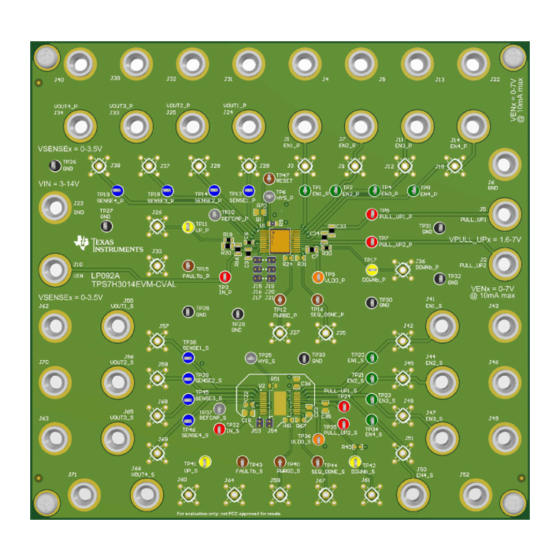
TPS7H3014EVM-CVAL Evaluation Module (EVM)
Description
The
TPS7H3014EVM-CVAL
operation of a single
TPS7H3014-SP
(ceramic package). The board provides footprints
that can be populated with additional components to
allow for testing of customized configurations, such as
daisy-chained sequencers.
SLVUCT9 – JANUARY 2024
Submit Document Feedback
demonstrates the
sequencer
Figure 1-1. EVM Board
Copyright © 2024 Texas Instruments Incorporated
Features
•
Flexible configuration options, including single-
device and daisy-chained device circuits.
•
Customizable delay timers, sense thresholds,
sense hysteresis, and sequence up/down
thresholds.
•
Footprints for optional external system reset
signal.
TPS7H3014EVM-CVAL Evaluation Module (EVM)
Description
1
Advertisement
Table of Contents

Related Manuals for Texas Instruments TPS7H3014EVM-CVAL


Summary of Contents for Texas Instruments TPS7H3014EVM-CVAL
-
Page 1: Description
• Footprints for optional external system reset signal. Figure 1-1. EVM Board SLVUCT9 – JANUARY 2024 TPS7H3014EVM-CVAL Evaluation Module (EVM) Submit Document Feedback Copyright © 2024 Texas Instruments Incorporated... -
Page 2: Table Of Contents
6 Additional Information................................32 6.1 Known Hardware Issues..............................7 Related Documentation................................32 8 Revision History................................... Trademarks All trademarks are the property of their respective owners. TPS7H3014EVM-CVAL Evaluation Module (EVM) SLVUCT9 – JANUARY 2024 Submit Document Feedback Copyright © 2024 Texas Instruments Incorporated... -
Page 3: Evaluation Module Overview
1 Evaluation Module Overview 1.1 Introduction The TPS7H3014EVM-CVAL is the Evaluation Module (EVM) for the ceramic package option of the TPS7H3014 and provides a platform to electrically evaluate its features. This user’s guide provides details about the EVM, including the configuration,schematics, and BOM. - Page 4 If VTH_SENSEx is not reached before the timer expires, the device will SENSEx Regulation Timer 12.35 ms sequence down. tREG_TMR Set by: R14 = 619 kΩ J20 shunted TPS7H3014EVM-CVAL Evaluation Module (EVM) SLVUCT9 – JANUARY 2024 Submit Document Feedback Copyright © 2024 Texas Instruments Incorporated...
- Page 5 Evaluation Module Overview 1.3.1 Alternate Board Configurations The TPS7H3014EVM-CVAL board provides footprints that can be populated with components for testing a "daisy-chain" configuration of 2 TPS7H3014-SP sequencers. The configuration is used to increase the number of monitored SENSEx inputs and ENx outputs that can be used for sequencing.
-
Page 6: Device Information
REG_TMR pin, or by floating the pin to allow infinite time for the SENSEx voltage to pass the on threshold. A standard microcircuit drawing (SMD) is available for the QML variants: 5962R23201VXC. TPS7H3014EVM-CVAL Evaluation Module (EVM) SLVUCT9 – JANUARY 2024 Submit Document Feedback Copyright © 2024 Texas Instruments Incorporated... -
Page 7: Hardware
1.6V ≤ VPULL_UPx ≤ 7V 2.2 Important Usage Notes The TPS7H3014EVM-CVAL board is configured so that the ENx signals are tied by a 0Ω resistor to their respective SENSEx signal. This configuration is purely for simplicity of testing device features and behavior when external voltages are not available to be sensed by the SENSEx pins. - Page 8 Probe test point EN4_S Probe test point Output connector for EN4 of Output connector for EN4 of the primary device. the secondary device. TPS7H3014EVM-CVAL Evaluation Module (EVM) SLVUCT9 – JANUARY 2024 Submit Document Feedback Copyright © 2024 Texas Instruments Incorporated...
- Page 9 TP10 REFCAP_P Test point TP37 REFCAP_S Test point TP47 RESET Test point External RESET will apply to both the primary and secondary device. SLVUCT9 – JANUARY 2024 TPS7H3014EVM-CVAL Evaluation Module (EVM) Submit Document Feedback Copyright © 2024 Texas Instruments Incorporated...
-
Page 10: Implementation Results
5. External System RESET 3.1 Default Configuration Results The following tests were performed using the TPS7H3014EVM-CVAL in the default configuration with VIN=12V and PULL_UP1=PULL_UP2=1.8V or 3.3V (indicated by voltage seen on the ENx, PWRGD, SEQ_DONE, and FAULT signals). All UP and DOWN sequences were initiated by raising or lowering VIN, as shown in the first two tests, unless stated otherwise. - Page 11 Implementation Results VIN<6V initiates sequence DOWN. EN2 goes LOW after DLY_TMR (12.35ms) expires. Figure 3-2. VIN Falling, Initiate Sequence DOWN SLVUCT9 – JANUARY 2024 TPS7H3014EVM-CVAL Evaluation Module (EVM) Submit Document Feedback Copyright © 2024 Texas Instruments Incorporated...
-
Page 12: Delay Timer
ENx signal to transition HIGH or LOW is met and when the ENx signal transitions. Figure 3-3. Sequence UP, 23ms Delay Figure 3-4. Sequence DOWN, 23ms Delay TPS7H3014EVM-CVAL Evaluation Module (EVM) SLVUCT9 – JANUARY 2024 Submit Document Feedback Copyright © 2024 Texas Instruments Incorporated... - Page 13 Implementation Results Figure 3-5. Sequence UP, 12ms Delay Figure 3-6. Sequence DOWN, 12ms Delay SLVUCT9 – JANUARY 2024 TPS7H3014EVM-CVAL Evaluation Module (EVM) Submit Document Feedback Copyright © 2024 Texas Instruments Incorporated...
- Page 14 Implementation Results www.ti.com Figure 3-7. Sequence UP, DLY_TMR Floating Figure 3-8. Sequence DOWN, DLY_TMR Floating TPS7H3014EVM-CVAL Evaluation Module (EVM) SLVUCT9 – JANUARY 2024 Submit Document Feedback Copyright © 2024 Texas Instruments Incorporated...
-
Page 15: Regulation Timer
Figure 3-9. Regulation Timer Expiration, 23ms Figure 3-10. Regulation Timer Expiration, 12ms SLVUCT9 – JANUARY 2024 TPS7H3014EVM-CVAL Evaluation Module (EVM) Submit Document Feedback Copyright © 2024 Texas Instruments Incorporated... - Page 16 Implementation Results www.ti.com Figure 3-11. Sequence UP, REG_TMR Floating Figure 3-12. Sequence DOWN, REG_TMR Floating TPS7H3014EVM-CVAL Evaluation Module (EVM) SLVUCT9 – JANUARY 2024 Submit Document Feedback Copyright © 2024 Texas Instruments Incorporated...
-
Page 17: Disabled Channels
The following tests were performed with SENSE3 and SENSE4 tied to 3.3V to disable channels 3 and 4. Figure 3-13. Sequence UP, CH3-4 Disabled Figure 3-14. Sequence DOWN, CH3-4 Disabled SLVUCT9 – JANUARY 2024 TPS7H3014EVM-CVAL Evaluation Module (EVM) Submit Document Feedback Copyright © 2024 Texas Instruments Incorporated... -
Page 18: Externally Induced System Reset
FET with low leakage to minimize the error it introduces to the SENSEx ON and OFF thresholds. Figure 3-15. Sequence UP Figure 3-16. External System RESET TPS7H3014EVM-CVAL Evaluation Module (EVM) SLVUCT9 – JANUARY 2024 Submit Document Feedback Copyright © 2024 Texas Instruments Incorporated... -
Page 19: Hardware Design Files
Note: 0-Ohm resistors connecting ENx to VOUTx are 0.1% 0.1% 100pF for simplicity of testing when external voltages are not available to sense. DNP if connecting external voltage to VOUTx. SLVUCT9 – JANUARY 2024 TPS7H3014EVM-CVAL Evaluation Module (EVM) Submit Document Feedback Copyright © 2024 Texas Instruments Incorporated... - Page 20 VOUT2_S=1.00 V with VON=85% and VOFF=50% VOUT3_S=1.20 V with VON=90% and VOFF=10% VOUT4_S=1.20 V with VON=97% and VOFF=95% Figure 4-1. Default EVM Schematic TPS7H3014EVM-CVAL Evaluation Module (EVM) SLVUCT9 – JANUARY 2024 Submit Document Feedback Copyright © 2024 Texas Instruments Incorporated...
- Page 21 0.1% 0.1% 100pF for simplicity of testing when external voltages are not available to sense. DNP if connecting external voltage Nb_P to VOUTx. SLVUCT9 – JANUARY 2024 TPS7H3014EVM-CVAL Evaluation Module (EVM) Submit Document Feedback Copyright © 2024 Texas Instruments Incorporated...
- Page 22 VOUT2_S=1.00 V with VON=85% and VOFF=50% VOUT3_S=1.20 V with VON=90% and VOFF=10% VOUT4_S=1.20 V with VON=97% and VOFF=95% Figure 4-2. Example: Daisy-Chain Configuration EVM Schematic TPS7H3014EVM-CVAL Evaluation Module (EVM) SLVUCT9 – JANUARY 2024 Submit Document Feedback Copyright © 2024 Texas Instruments Incorporated...
-
Page 23: Pcb Layouts
Hardware Design Files 4.2 PCB Layouts Figure 4-3. Top Overlay Figure 4-4. Top Solder Mask SLVUCT9 – JANUARY 2024 TPS7H3014EVM-CVAL Evaluation Module (EVM) Submit Document Feedback Copyright © 2024 Texas Instruments Incorporated... - Page 24 Hardware Design Files www.ti.com Figure 4-5. Layer 1 (Top) Figure 4-6. Layer 2 TPS7H3014EVM-CVAL Evaluation Module (EVM) SLVUCT9 – JANUARY 2024 Submit Document Feedback Copyright © 2024 Texas Instruments Incorporated...
- Page 25 Hardware Design Files Figure 4-7. Layer 3 Figure 4-8. Layer 4 (Bottom) SLVUCT9 – JANUARY 2024 TPS7H3014EVM-CVAL Evaluation Module (EVM) Submit Document Feedback Copyright © 2024 Texas Instruments Incorporated...
- Page 26 Hardware Design Files www.ti.com Figure 4-9. Bottom Solder Mask Figure 4-10. Bottom Overlay TPS7H3014EVM-CVAL Evaluation Module (EVM) SLVUCT9 – JANUARY 2024 Submit Document Feedback Copyright © 2024 Texas Instruments Incorporated...
- Page 27 Hardware Design Files Figure 4-11. Drill Drawing SLVUCT9 – JANUARY 2024 TPS7H3014EVM-CVAL Evaluation Module (EVM) Submit Document Feedback Copyright © 2024 Texas Instruments Incorporated...
-
Page 28: Bill Of Materials (Bom)
Panasonic Electronic 60.4k 0.125W(1/8W) ±25ppm/C Pad SMD Automotive 0805 ERA-6AEB6042V Components 49.9k RES, 49.9 k, 0.1%, 0.125 W, 0805 0805 RT0805BRD0749K9L Yageo America TPS7H3014EVM-CVAL Evaluation Module (EVM) SLVUCT9 – JANUARY 2024 Submit Document Feedback Copyright © 2024 Texas Instruments Incorporated... - Page 29 TP26, TP27, TP28, TP29, Test Point, Multipurpose, Black, TH Multipurpose Testpoint 5011 Keystone Electronics TP30, TP31, TP32, TP33 Radiation-Hardeness-Assured, 14-V, 4-Channel CFP22 TPS7H3014HFT/EM Texas Instruments Sequencer SLVUCT9 – JANUARY 2024 TPS7H3014EVM-CVAL Evaluation Module (EVM) Submit Document Feedback Copyright © 2024 Texas Instruments Incorporated...
- Page 30 RES, 10.0 k, 0.1%, 0.2 W, AEC-Q200 Grade 0, R62, R70 10.0k 0805 MCU0805MD1002BP100 Vishay/Beyschlag 0805 40.2k RES, 40.2 k, 0.1%, 0.125 W, 0805 0805 RG2012P-4022-B-T5 Susumu Co Ltd TPS7H3014EVM-CVAL Evaluation Module (EVM) SLVUCT9 – JANUARY 2024 Submit Document Feedback Copyright © 2024 Texas Instruments Incorporated...
- Page 31 RP73PF2A1K0BTDF TE Connectivity 1.07k RES, 1.07 k, 0.1%, 0.125 W, 0805 0805 RT0805BRD071K07L Yageo America Radiation-Hardeness-Assured, 14-V, 4-Channel CFP22 TPS7H3014HFT/EM Texas Instruments Sequencer SLVUCT9 – JANUARY 2024 TPS7H3014EVM-CVAL Evaluation Module (EVM) Submit Document Feedback Copyright © 2024 Texas Instruments Incorporated...
-
Page 32: Compliance Information
5.1 Compliance and Certifications • Texas Instruments, TPS7H3014EVM-CVAL EU RoHS Declaration of Conformity (DoC) 6 Additional Information 6.1 Known Hardware Issues 1. An initial build of this board has duplicate designators for 2 test points. Both the RESET and EN1_S test points were listed as TP20. - Page 33 STANDARD TERMS FOR EVALUATION MODULES Delivery: TI delivers TI evaluation boards, kits, or modules, including any accompanying demonstration software, components, and/or documentation which may be provided together or separately (collectively, an “EVM” or “EVMs”) to the User (“User”) in accordance with the terms set forth herein.
- Page 34 www.ti.com Regulatory Notices: 3.1 United States 3.1.1 Notice applicable to EVMs not FCC-Approved: FCC NOTICE: This kit is designed to allow product developers to evaluate electronic components, circuitry, or software associated with the kit to determine whether to incorporate such items in a finished product and software developers to write software applications for use with the end product.
- Page 35 www.ti.com Concernant les EVMs avec antennes détachables Conformément à la réglementation d'Industrie Canada, le présent émetteur radio peut fonctionner avec une antenne d'un type et d'un gain maximal (ou inférieur) approuvé pour l'émetteur par Industrie Canada. Dans le but de réduire les risques de brouillage radioélectrique à...
- Page 36 www.ti.com EVM Use Restrictions and Warnings: 4.1 EVMS ARE NOT FOR USE IN FUNCTIONAL SAFETY AND/OR SAFETY CRITICAL EVALUATIONS, INCLUDING BUT NOT LIMITED TO EVALUATIONS OF LIFE SUPPORT APPLICATIONS. 4.2 User must read and apply the user guide and other available documentation provided by TI regarding the EVM prior to handling or using the EVM, including without limitation any warning or restriction notices.
- Page 37 Notwithstanding the foregoing, any judgment may be enforced in any United States or foreign court, and TI may seek injunctive relief in any United States or foreign court. Mailing Address: Texas Instruments, Post Office Box 655303, Dallas, Texas 75265 Copyright © 2023, Texas Instruments Incorporated...
- Page 38 TI products. TI’s provision of these resources does not expand or otherwise alter TI’s applicable warranties or warranty disclaimers for TI products. TI objects to and rejects any additional or different terms you may have proposed. IMPORTANT NOTICE Mailing Address: Texas Instruments, Post Office Box 655303, Dallas, Texas 75265 Copyright © 2024, Texas Instruments Incorporated...
Need help?
Do you have a question about the TPS7H3014EVM-CVAL and is the answer not in the manual?
Questions and answers