
Related Manuals for Vimar 0K03800.02


Summary of Contents for Vimar 0K03800.02
- Page 1 Installer manual By-alarm Plus burglar alarm system Installation Manual BY-ALARM PLUS...
- Page 2 By-alarm Plus...
-
Page 3: Table Of Contents
By-alarm Plus Index 1. General characteristics . . . . . . . . . . . . . . . . . . . . . . . . . . . . . . . . . . . . . . . . . . . . . . . . . . . . . . . . . . . . . . . . . . . . . . . . . . . . . . . . . . . . . . . . . . . . . . . . . . . . . . . . . . 1 .1 Main components of the By-alarm Plus system . -
Page 4: General Characteristics
By-alarm Plus General characteristics 1. General characteristics The By-alarm Plus system is latest-generation hybrid burglar alarm system dedicated to protecting people and property from unauthorised access . It comprises a set of wired devices/peripherals (connected to the system by BUS) and a set of via-radio devices/peripherals . The system stands out due to the following features: •... - Page 5 By-alarm Plus General characteristics • LTE communicators They notify users and installers of system events via the mobile network operators . They operate in the 2G, 3G and 4G networks that the peripheral automatically selects (according to the best technology available in the location of the system installation) and send voice messages and text messages . The user may also send text messages to the peripheral to give the system controls .
-
Page 6: How To Create A System
By-alarm Plus How to create a system 2. How to create a system Below is a description of the different ways a By-alarm Plus system can be created . In actual fact each method is not mutually exclusive from the next and so the installer will decide the most appropriate one to use . -
Page 7: The Control Unit
By-alarm Plus The control unit 3. The control unit The microcontroller-based control unit, available in versions with 25, 65 and 125 zones (art . 03800, 03801 and 03802, respectively) has 10 expandable input/output lines and is managed through the LCD keypad art . 03817 and 03818 with actuator 03824; it has 1 programmable relay, 2 open-collector outputs and 3 auxiliary 12 V outputs . The voice synthesis card 03813 and the GSM transceiver module 03810-03820 can be connected to the control unit . -
Page 8: System Sizing Criteria
By-alarm Plus The control unit 3.3 System sizing criteria This paragraph illustrates the flow diagram with the criteria to follow for the correct sizing of the system in relation to the desired range and to the consumption levels of the devices in the By-alarm Plus system . START Does the system need to comply with EN50131... - Page 9 By-alarm Plus The control unit Devices in the By-alarm Plus system and their consumption levels Article Description Notes Absorption 03808 5 In/Out expansion card 20 mA 03809 Relay interface card 30 mA In transmission 540 mA 03810 GSM 4G communicator card Stand-by 70 mA 03813...
-
Page 10: Functional Characteristics And Manageable Devices
By-alarm Plus The control unit 3.4 Functional characteristics and manageable devices Control unit 03800 03801 03802 Areas Total zones Keyboards Expansions Readers Sirens Radio transceivers Isolators GSM/LTE communicator User profiles Users Possible user PIN combinations 1000000 Electronic keys/remote controls Possible key combinations 4294967296 Possible remote control combinations 16777216... -
Page 11: Activity Leds And What They Mean
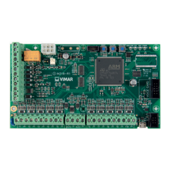
By-alarm Plus The control unit SERV/ENR SERV/ENR RESET FACTORY EXE BUS POWER Connector for power supply unit POWER-IN Activity LEDs Anti-tamper TAMPER Push buttons Connector for voice synthesis card 03813. Connector for gateway 03812 Mini USB connector for Earth cable connection connection to the PC AUX2 AUX3... -
Page 12: Serv/Enr Led
By-alarm Plus The control unit 3.6.1 SERV/ENR LED The red LED indicates the following phases: on steady = control unit under MAINTENANCE (**, see the paragraph concerning the MAINTENANCE status hereunder); certain functions are forbidden, such as the processing of alarms and sabotages off = control unit fully operating normally, all the processing is active flashing = control unit in peripheral on BUS acquisition phase;... -
Page 13: Installing The Control Unit
By-alarm Plus The control unit 3.10 Installing the control unit The control unit card can be installed together with other peripherals inside the following articles: • Art . 03814 By-alarm Plus plastic box for 25- or 65-zone control unit card, 2 slots available for 5 In/Out expansion card 03808, GSM communicator card 03810 or burglar alarm system gateway 03812, 1 slot available for radio module 03832, 1 3 .2A power supply unit 03805, 1 housing for 7Ah battery, anti-removal and anti-tamper protection, surface mounting . -
Page 14: Connecting The Pc
By-alarm Plus The control unit 3.12 Connecting the PC This can be done in the following ways: • USB: this is a direct connection to the control unit via the USB port . The connection operation depends on the installation of the drivers for communication via USB which are normally available on PCs where Microsoft® Windows® is installed . -
Page 15: Connecting The Peripherals To The Control Unit Bus
By-alarm Plus Connecting the peripherals to the control unit bus 4. Connecting the peripherals to the control unit bus Connection of peripherals to the control unit is with a 4-wire (or more) shielded cable . Caution: Connect the shield to one of the earth (or GND) terminals at the control unit end only, and ensure that it follows the entire BUS without being connected to earth at any other point. -
Page 16: Indications For Terminals Programmed As No (Norm . Open)
By-alarm Plus Connecting the peripherals to the control unit bus The length (L) indicated here corresponds: • in the case of a single line, to the length of the cables between an isolator and the subsequent peripherals or between two subsequent isolators . •... - Page 17 By-alarm Plus Connecting the peripherals to the control unit bus 4.2 Connecting isolators The isolators have a dual purpose: - to regenerate the electrical signals of the BUS which deteriorate in the presence of long sections or in the presence of multiple connected devices; - isolate the BUS itself galvanically both to protect it from tampering and for the correct management of the additional auxiliary power supplies The articles available in the range are: art .
- Page 18 By-alarm Plus Connecting the peripherals to the control unit bus Integrated regenerated power supply and regeneration of BUS signals If the current required to power the BUS peripherals is less than 1A, then isolator art . 03823 can be used as it is equipped with an integrated switching power supply unit capable of supplying 13 .8V@1A .
-
Page 19: Connecting Alarm Sensors And Balancing
By-alarm Plus Connecting alarm sensors and balancing 5. Connecting alarm sensors and balancing Connecting sensors (detectors) and balancing them depends on their type and on the protection degree you wish to achieve . Sensors can be powered: • by terminals [+AUX/12V] and [-/earth] present on the control unit •... -
Page 20: Double Balancing
By-alarm Plus Connecting alarm sensors and balancing Note The level of protection of the single balancing is as safe as the double balancing if the sabotage contact of the sensor is connected to a balanced input. 5.3 Double balancing Double balancing (often indicated as double end-of-line resistor or double EOL) uses two resistors, for which four statuses of the terminal which they are connected to can be detected: •... -
Page 21: Connecting Roller Shutter/Inertia Sensors And Balancing
By-alarm Plus Connecting alarm sensors and balancing 5.5 Connecting roller shutter/inertia sensors and balancing In the case of roller shutter or inertia detectors, you can choose between two balancing types: • normally closed (NC) • single balancing (similar to NC with EOL resistor) . The table below shows the relationship between the level of protection of roller shutter or inertia sensors with the two envisaged control unit balancing types: N.C. -
Page 22: Connecting Sirens
By-alarm Plus Connecting sirens 6. Connecting sirens 6.1 Connecting an outdoor siren and an indoor siren using a single relay The relay output of the control unit should be configured by default in other words as ACTIVATION CAUSE (BURGLAR ALARM – BURGLARY/SABOTAGE/SYSTEM SABOTAGE/PANIC –... -
Page 23: Connecting An Outdoor Siren And An Indoor Siren With Separate Control
By-alarm Plus Connecting sirens 6.2 Connecting an outdoor siren and an indoor siren with separate control The OC1 output of the control unit should be configured as ACTIVATION CAUSE (BURGLAR ALARM – BURGLARY/SABOTAGE/SYSTEM SABOTAGE/PANIC – AREA 1) . The AUX1 output of the control unit should be configured as ACTIVATION CAUSE (BURGLAR ALARM – BURGLARY/SABOTAGE/SYSTEM SABOTAGE/PANIC – AREA 1-DO NOT PARTIALLY ACTIVATE) . -
Page 24: Connecting An Outdoor Siren Using "Start" And "Stop" And An Indoor Siren With Separate Control
By-alarm Plus Connecting sirens 6.3 Connecting an outdoor siren using “START” and “STOP” and an indoor siren with separate control The outdoor siren should be kept at its default configuration . A terminal of the control unit or of an In/Out expansion or of the keypad should be configured as an OUTPUT and as ACTIVATION CAUSE (BURGLAR ALARM – BUR- GLARY/SABOTAGE/SYSTEM SABOTAGE/PANIC –... - Page 25 By-alarm Plus Connecting sirens Characteristics of the START and STOP terminals The START and STOP terminals operate in a static manner, in other words, depending on their on/off status, they determine the behaviour of the siren . In practice, the operation of the siren is NOT determined by pulses on START and STOP . Keep in mind that the on/off status of the START and STOP terminals is aligned with the configuration assigned to the “START Input”...
-
Page 26: Outdoor Siren Led Control
By-alarm Plus Connecting sirens 6.4 Outdoor siren LED control The outdoor siren should be kept at its default configuration . A terminal of the control unit, or of an In/Out expansion or of the keypad should be configured as an OUTPUT and connected to the LED terminal of the outdoor siren; the latter should be configured as ACTIVATION CAUSE for a control unit event for which you wish to trigger the signalling on the LED of the outdoor siren . -
Page 27: Connecting Outputs
By-alarm Plus Connecting outputs 7. Connecting outputs 7.1 Auxiliary power supply terminals The +OC terminal is an auxiliary 13 .8 V power supply terminal with a maximum current of 350 mA . 7.2 Programmable, supervised auxiliary power supply terminals The AUX1, AUX2 and AUX3 terminals are programmable, supervised 13 .8 V auxiliary power supply terminals with a maximum current of 1 .5 A . They are protected against voltage and current surges and short circuits . -
Page 28: Routing Peripherals
By-alarm Plus Routing peripherals - First power-up - Integration with the By-me Plus home automation system 8. Routing peripherals All the peripherals connected to the BUS must have unequivocal logic addresses to be correctly identified by the control unit . Different types of peripherals can have the same address (for instance address 3 for a keypad and for an expansion), whereas two peripherals of the same type must under no circumstances have the same address . -
Page 29: Accessing The Keypad As An Installer User
By-alarm Plus Integration with the By-me Plus home automation system 10.2 Accessing the keypad as an Installer user Press and hold down button at length then enter the Installer PIN (the default value is “9999”) . The list of available menus is displayed: •... -
Page 30: Faults Viewable On The Keypad
By-alarm Plus Faults viewable on the keypad 11. Faults viewable on the keypad ADDITIONAL DESCRIPTION FAULT on keypad SUB-FAULT on keypad FAULT DESCRIPTION SUB-FAULT DESCRIPTION on keypad Control unit AC mains power No primary power supply supply interruption Overload Maximum current exceeded Over-temperature Over-temperature Problem with power supply... - Page 31 By-alarm Plus Faults viewable on the keypad ADDITIONAL DESCRIPTION FAULT on keypad SUB-FAULT on keypad FAULT DESCRIPTION SUB-FAULT DESCRIPTION on keypad Date and time at factory Date and time lost settings Channel 1 blacked out Disturbance or jamming at- Channel 2 blacked out Radio channel black-out tempt on one of the via-radio Channel 3 blacked out...
-
Page 32: Troubleshooting
By-alarm Plus Troubleshooting 12. Troubleshooting Make sure the Installer PIN entered is correct (9999 by default) . Disconnect the connector and check the list of COM ports available . After re-connecting the USB connector a new COM port is displayed; select it and Connection via USB cable not working - User not recognised perform the connection check . - Page 33 By-alarm Plus...
- Page 34 Viale Vicenza 14 36063 Marostica VI - Italy By-alarm Plus 02 2309 www.vimar.com...
Need help?
Do you have a question about the 0K03800.02 and is the answer not in the manual?
Questions and answers