Table of Contents
Advertisement
Operation &
Maintenance Manual
FORKLIFTS
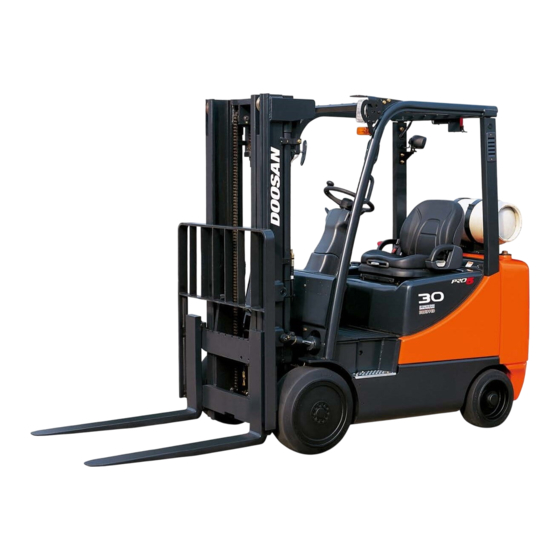
D20S-5, D25S-5, D30S-5, D33S-5, D35C-5
FDA04, FDA05, FDA06, FDA07, FDA08 (Yanmar 3.3L/3.0L Tier-3)
G20E-5, G25E-5, G30E-5
FGA07, FGA08, FGA09 (HMC 2.4L Tier-3)
GC20E-5, GC25E-5, GC30E-5, GC33E-5
FGA0K, FGA0L, FGA0M, FGA0N (HMC 2.4L Tier-3)
G20P-5, G25P-5, G30P-5, G33P-5, G35C-5
FGA0A, FGA0B, FGA0C, FGA0D, FGA0E (MMC 2.4L Tier-3)
G20P-5 Plus, G25P-5 Plus,
G30P-5 Plus, G33P-5 Plus, G35C-5 Plus
FGB0H, FGB0J, FGB0K, FGB0L, FGB0M (GM 3.0L Tier-3)
GC20P-5, GC25P-5, GC30P-5, GC33P-5
FGA0P, FGA0R, FGA0S, FGA0T (MMC 2.4L Tier-3)
Original Instruction
SB2349E10
1703
Advertisement
Chapters
Table of Contents


Need help?
Do you have a question about the D35C-5 FDA04 and is the answer not in the manual?
Questions and answers