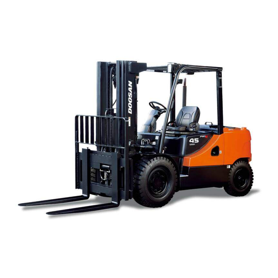
Doosan D35S-5 Disassembly/Assembly

Doosan D35S-5 Disassembly/Assembly

Vehicle system
Hide thumbs Also See for D35S-5:

Advertisement

Vehicle System
Disassembly & Assembly
D35S-5, D40S-5, D45S-5, D50C-5, D55C-5
D40SC-5, D45SC-5, D50SC-5, D55SC-5
G35S-5, G40S-5, G45S-5, G50C-5, G55C-5
G40SC-5, G45SC-5, G50SC-5, G55SC-5
GC35S-5, GC40S-5, GC45S-5
GC50C-5, GC55C-5
SB4267E00
May. 2007

Advertisement

Table of Contents
loading
Need help?

Need help?

Do you have a question about the D35S-5 and is the answer not in the manual?

Questions and answers

Summary of Contents for Doosan D35S-5

  • Page 1 SB4267E00 May. 2007 Vehicle System Disassembly & Assembly D35S-5, D40S-5, D45S-5, D50C-5, D55C-5 D40SC-5, D45SC-5, D50SC-5, D55SC-5 G35S-5, G40S-5, G45S-5, G50C-5, G55C-5 G40SC-5, G45SC-5, G50SC-5, G55SC-5 GC35S-5, GC40S-5, GC45S-5 GC50C-5, GC55C-5...
  • Page 3 If a tool, procedure, work method or operating technique not specifically recommended by DOOSAN is used, you must satisfy yourself that it is safe for you and others. You should also ensure that the product will not be damaged or made unsafe by the operation, lubrication, maintenance or repair procedures you choose.
  • Page 5: Table Of Contents

    Index Disassembly & Assembly....... 5 Hood (with seat) ............ 5 Overhead Guard............ 6 Tilt Cylinders ............7 Secondary Lift Cylinders........9 Primary Lift Cylinder ..........12 Hydraulic Control Value ........15 Washing .............. 17 Inspection............17 Assembling............18 Relief Valve Maintenance ........20 Steering Wheel............
  • Page 7: Disassembly & Assembly

    Disassembly & Assembly Hood (with seat) Remove & Install Hood (with seat) Assembly 5. Remove the washers and four bolts (3). WARNING The hood and seat assembly can fall when nut (1) is removed from the support cylinder rod. To avoid personal injury, support the seat and hood assembly before removing nut (1).
  • Page 8: Overhead Guard

    Overhead Guard Remove & Install Overhead Guard 3. Remove the washers, nuts, and two bolts (3). 4. Remove front overhead guard (1), Front overhead guard (1) weighs approximately 30 kg (66 lb). 1. Support overhead guard (1) with lifting straps and 5.
  • Page 9: Tilt Cylinders

    Tilt Cylinders Remove & Install Tilt Cylinders NOTE: The procedure for removing and installing the tilt cylinders is the same for both cylinders. WARNING If both tilt cylinders are removed at the same time the mast can fall. To avoid possible personal injury, make sure the mast is securely held in place or supported by a hoist before 2.
  • Page 10 Disassemble & Assemble Tilt Cylinders Start By: a. Remove tilt cylinder. 4. Remove pin (5) inside hole and nut (6) from the cylinder rod (4). 5. Remove piston (7) from the cylinder rod. 1. Remove eye (1) from the rod assembly (4). 6.
  • Page 11: Secondary Lift Cylinders

    Secondary Lift Cylinders Disassemble Secondary Lift Cylinders Start By : a. Remove secondary lift cylinders. 8. Remove O-ring seal (11) and backup ring (12) from the rod cover (2). 1. Put secondary lift cylinder (1) in position as shown. 9. Remove wiper seal (13), backup ring (14), U- packing (15) and DU-bush (16) from the rod cover.
  • Page 12 4. Remove retaining ring (4) and piston (5) from the 7. Remove O-ring seal (10) from the head assembly. cylinder rod. 5. Remove O-ring seal (6) from the cylinder rod. 8. Remove wiper seal (11), seal (12) and bush (13) from the head assembly.
  • Page 13 Assemble Secondary Lift Cylinders 5. Install O-ring seal (6) on the cylinder rod. 1. Install bush (13) and seal (12). 2. Install wiper seal (11). Install the seal with the lip toward the outside. 6. Install piston (5) and retaining ring (4) on the cylinder rod.
  • Page 14: Primary Lift Cylinder

    8. Install head assembly (2) on the cylinder rod and 1. Fasten nylon straps and hoist to the primary lift tighten using tool. cylinder. End By : 2. Remove bolt (1). a. Install secondary lift cylinders. Primary Lift Cylinder Remove & Install Primary Lift Cylinder Start By : a.
  • Page 15 Disassemble Primary Lift Cylinder Start By : a. Remove primary lift cylinder. 4. Remove O-ring seal (4) and back-up ring (5) from the bearing. 1. Remove bearing (1). 2. Remove rod (2) from the cylinder body. 5. Remove wiper seal (6), back-up ring (7), seal (8) and rings (9) from the bearing.
  • Page 16 Assemble Primary Lift Cylinder 5. Install split rings (3) on the cylinder. 1. Install back-up ring (7) and seal (8) in the bearing. Install the seal with the lip toward the inside. 2. Install wiper seal (6). Install the seal with the lip toward the outside.
  • Page 17: Hydraulic Control Value

    Hydraulic Control Value 2. Slowly remove each spool section assembly in the reverse order as in the outlet section. Take care not to lose poppet, springs, or o-rings in Disassembling the fitting face of each section. Keep following precautions for disassembling. 3.
  • Page 18 2. Hold the spool (2) on a vise by inserting rigid 11. Take out plug(34) and remove spring(33) and wood pieces(Fig. 2-1) etc. to prevent damage on poppet assembly(32). the surface. Remove the cap screw(11), Then, remove the main poppet from the poppet disassemble spring seat(7) and spring(6), and assembly(32).
  • Page 19: Washing

    Washing 4. Hold the spool(2) in a vise using rigid wood pieces(Fig. 2-1) to prevent damage. Remove cap screw(8) and remove spring seat(7), spring(9), Wash all the disassembled parts completely with wiper(5) and O-ring(4). At this time, take care that mineral oil.
  • Page 20: Assembling

    Assembling Spool Subassembly With reference to the attached Part List of each Take following cares when handling the O-rings. section assemblies, mount O-ring, wiper and seal plate on the spool in specified order. Insert spring 1. Do not use any defective O-ring, whether the between the spring seats and mount it on the spool defect was made in forming or handling, with cap screw.
  • Page 21 Assembling Inlet Section Assembly 7. Insert shuttle(36) into spring(37) and insert them into inlet hosing(1). At this time, the shuttle(36) may be ejected out by Combination number shall be in accordance with the spring(37) force. Place the solenoid(38) on the attached Part List (P/N: C0213-41001).
  • Page 22: Relief Valve Maintenance

    Relief Valve Maintenance Assembling Spool Section Assembly The combination numbers shall in accordance with Main Relief Valve, Second Relief Valve the pertinent Parts List. Tightening torques of each part must be in Disassembling compliance with the Parts List. The combination numbers shall be in accordance 1.
  • Page 23 Washing, Inspection 5. At the specified pressure, hold the adjuster and tighten with lock nut. Specified torque: 27~31N Wash all parts with clean mineral oil. Dry with ・m compressed air for inspection. 6. Raise the pressure again to check if the specified 1.
  • Page 24 Ref.No. GZ-MS-V0030 Vehicle Systems Disassembly & Assembly...
  • Page 25 Ref.No. GZ-MS-V0030 Vehicle Systems Disassembly & Assembly...
  • Page 26 Ref.No. GZ-MS-V0030 Vehicle Systems Disassembly & Assembly...
  • Page 27 Ref.No. GZ-MS-V0030 Vehicle Systems Disassembly & Assembly...
  • Page 28 Ref.No. GZ-MS-V0030 Vehicle Systems Disassembly & Assembly...
  • Page 29 Ref.No. GZ-MS-V0030 Vehicle Systems Disassembly & Assembly...
  • Page 30 Ref.No. GZ-MS-V0030 Vehicle Systems Disassembly & Assembly...
  • Page 31: Steering Wheel

    Steering Wheel Remove & Install Steering Wheel 1. Remove cap (1) from the steering wheel. 2. Remove nut (2) and washer (3) from the steering wheel shaft. Put location marks on the steering wheel and the steering wheel shaft for installation purposes.
  • Page 32: Steering Unit

    Steering Unit 1. Disconnect (4) tubes and (1) hose assembled to steering unit. Remove & Install Steering Unit Start By: a. Remove covers from steering wheel group WARNING To prevent personal injury be sure pressure in the hydraulic system has been released before disconnecting any hydraulic lines.
  • Page 33 Disassemble Steering Unit Cleanliness is extremely important when repairing a steering unit. Work in a clean area. Before disconnecting lines, clean port area of unit thoroughly. Use a wire brush to remove foreign material and debris from around exterior joints of the unit. Although not all drawings show the unit in a vise, we recommend that you keep the unit in the vise during disassembly.
  • Page 34 Seal Gland Bushing Spacer Plate Drive IDCD283S Seal 12. Rotate spool and sleeve until pin is horizontal. Push spool and sleeve assembly forward with your thumbs just far enough to free gland IDCD281S bushing from housing. Remove bushing. 8. Remove drive. 9.
  • Page 35 Bearing Needle Race Thrust Bearing Bearing Race IDCD285S IDCD287S 15. Remove 2 bearing races and the needle thrust 18. Push spool partially from control end of sleeve, bearing from spool and sleeve assembly. then remove 4 centering springs from spool carefully by hand.
  • Page 36 Assemble Steering Unit Check all mating surfaces. Replace any parts that have scratches or burrs that could cause leakage. Spring Slot Clean all metal parts in clean solvent. Blow dry with air. Control Sleeve Do not wipe dry with cloth or paper towel because lint Spring Slot or other matter can get into the hydraulic system and cause damage.
  • Page 37 Needle Thrust Bearing Bearing Race(2 Seal IDCD292S 11. Position the spool and sleeve assembly so that the splined end of the spool enters the 14 hole end of housing first. IDCD293S ATTENTION: Be extremely careful that the parts do not tilt out of position while inserting. Push parts 12.
  • Page 38 Retainin g Ring Seal Gland Bushing (with seals) IDCD294S IDCD296S 16. Install seal gland bushing over the spool end 18. Clamp housing in vise. Clamp lightly on edges of with a twisting motion. Tap the bushing in place mounting area. Do not over tighten jaws. with a rubber hammer.
  • Page 39 Seal Groove this Side of Gerotor (Meter) Star Valley Port Face Drive Drive Pin Parallel (Marked) with Port Face IDCD298S 21. Rotate spool and sleeve assembly until pin is parallel with port face. Install drive, make sure Port Face you engage drive with pin. To assure proper IDCD300S alignment, mark...
  • Page 40 24. Install drive spacer (s) when used, in meter. 25. Install 73.5 mm [2.89 in.] ID seal in gerotor (meter) or end cap, see notes. Seal Drive Spacer(s) 26. Install end cap on gerotor, align holes. IDCD301P IDCD302P Actual Spacer Displacement Length mm [in.] 27.
  • Page 41: Brake Hydraulic Booster

    Brake Hydraulic Booster 1. Installation is the reverse order of removal. Be sure to check the leakage between the connections. Remove and Install Brake Hydraulic Booster 2. Remove the air (bleed the brake lines). See the topic of Brake System Air Removal. Flow Control Valve 3.
  • Page 42 Disassemble & assemble brake valve 1. Take off bellows (4) and lift push rod (3), remove vent air (25) and bolts (28). 2. Separate the front housing (1) and rear housing (2), remove servo spring (10), servo piston (9) and master piston (5).
  • Page 43 3. Take off seal u-cup (14) from master piston (5). Notice the direction of the seal. 4. Remove lock washer (6) and ball (7) from servo piston (9). Pull off piston ring (8), seal u-cup (13), seal u- cup (12) and seal u-cup (11) in sequence. Notice the direction of each seal. Color Material Translucency...
  • Page 44 5. Remove relief plug (18), o-ring (19), spring (17), shims (16) and piston (15) from front housing (1). 6. Remove check valve parts from rear housing (2): plug (26), o-ring (27), cage (24), spring (23), ball (21) and o-ring (22). Remove o-ring (20). 7.
  • Page 45: Tie Rods

    Tie Rods 6. Install the tie rod in the reverse order of removal. Remove And Install Tie Rods Tools Needed Floor Jack Drive Set Start By : a. Remove steer wheels. NOTE: The procedure to remove and install the tie rod is the same for each steer wheel.
  • Page 46: Steering Knuckles, Kingpins, And Bearings

    Steering Knuckles, Kingpins, And Bearings Remove And Install Steering Knuckles, King Pins And Bearings Tools Needed Drive Set Start By: 4. Remove four bolts (5) and cover (6). a. remove steer wheels NOTE: The procedure to remove and install the steering knuckles, kingpins, and bearings is the same for both sides of the lift truck.
  • Page 47: Steer Axle

    Steer Axle Remove & Install Steer Axle Tools Needed Jack Stand WARNING Be sure the pressure in the hydraulic system is released before any lines or hoses have been 6. Remove kingpin (8) and knuckle (9). disconnected. 7. Remove spacer (11), bearing cup (13) and bearing cone (12).
  • Page 48: Steering Cylinder

    Steering Cylinder 6. Remove bolts (2) and mounting caps (3) from the steer axle. Remove & Install Steering Cylinder 7. Remove steer axle (4). The steer axle weighs180 kg (400 lb). NOTE : Use the following steps to install the steer axle.
  • Page 49 Disassemble And Assemble Steering Cylinder Start By : a. Remove steering cylinder. 4. Remove retaining ring (5) with a plier and ring (6) from each side of piston (7) that holds piston in position on rod (3). 5. Remove piston (7) from the rod (3). 1.
  • Page 50: Tires And Rims (Steer)

    Tires And Rims (Steer) Remove And Install Tires And Rims (Steer) 9. Remove O-ring seal (12) and backup ring (13) from each head (1). 1. Put a hydraulic jack in position under the steer axle. 2. Loosen nuts (1) that hold the tire and rim in place. 3.
  • Page 51: Hydraulic Control Valves

    Hydraulic Control Valves Remove And Install Hydraulic Control Valves WARNING Hydraulic oil under pressure can remain in the hydraulic system after the engine and pump have been stopped. Personal injury can result if the pressure is not released before any work is done to the hydraulic system.
  • Page 52: Hydraulic Pump

    Hydraulic Pump Remove and Install Hydraulic Pump Start By : a. Remove counterweight. 1. Drain the oil from the hydraulic tank. 2. Disconnect three oil lines (1) from the pump elbows. 3. Fasten a hoist to pump (5). Remove bolts (4) that hold the pump in place. Remove the pump and plate assembly.
  • Page 53: General Instruction

    General Instruction Disassembly Process Cleanliness Rear section 1. Cleanliness is the primary means of assuring Loosen and remove the clamp bolts (18) from rear satisfactory hydraulic pump life. working section (1). Components such as flanges and covers are best cleansed in soap and hot water, then air dried. Related parts Gears should be washed in solvent, air dried, and Washer (22), Rear cover (4), Dowel pin(35),...
  • Page 54 Center section 4. Remove through shaft(34) from driving shaft(14). 5. Loosen and remove the clamp bolt(17) with washer(21), and then remove the working section(3) from mounting flange(5) 1. Remove through shaft (33) from driving shaft (11). Related parts. Square ring(25), Dowel pin (35) 2.
  • Page 55 Reassembly Process Center section Information for assembly way of thrust plates It is important that all of thrust plate parts in this hydraulic pump should be assembled such as below picture during reassembly. Picture 8, 9 show assembling sequence and direction. 1.
  • Page 56 4. Insert the driving gear (14) and driven gear (15) 8. Locate the o-ring (23) on the groove ore-arranged into working section (3) while keeping the gears on the thrust plate (8). straight. Locate thrust plate(9+24+30) with care for the 9.
  • Page 57 11. Insert the through shaft (33) into driving shaft 3. Locate the driving gear(10) and driven gear(12) (11), and then locate the working body (2) and with thrust plate parts(8+23+29) into working flange (32) after inserting the squaring ring (26) section(2).
  • Page 58: Counterweight

    Counterweight Remove And Install Counterweight 6. Tighten the bolt (18) with washer (22) in a cross pattern to torque valve of 45Nm. Check that the pump rotate freely when the driving shaft is turned by hand. If not a thrust plate seal may be pinched.
  • Page 59: Hydraulic Oil Filter Assembly

    Hydraulic Oil Filter Assembly 1. Raise the machine until tires are approximately 1 to 2 inches off of the floor. Position the machine on tooling (A). Remove And Install Hydraulic Oil Filter Assembly 2. Disconnect brake tubes (7) and parking cables from drive axle.
  • Page 60: Engine

    b. Install mast * * Refer to the Mast System Disassembly & Assembly Section for further information. Engine Remove & Install Engine Tools Needed Link Bracket 7. Support the engine with a hoist and tooling (B). NOTE: Procedures for LP gas and diesel engines are all similar.
  • Page 61 2. Disconnect air intake hose (4). 3. Disconnect battery cables and remove battery (5) and battery tray assembly. 7. Disconnect engine wire harness (8). Disconnect wires from the alternator (9). To remove engine from the truck, other wires or connectors not shown should be disconnected.
  • Page 62 11. Remove bolts (14) and nuts from two engine mounts, located on each side of the engine. NOTICE Make sure the engine is supported underneath by suitable wooden blocks. Failure to support engine will result in possible damage. 13. Remove the engine with a hoist. 14.

Table of Contents

Save PDF