Epson TM-U220-i Technical Reference Manual
Hide thumbs
Also See for TM-U220-i:
- User manual (48 pages) ,
- User manual (72 pages) ,
- User manual (22 pages)
Table of Contents
Advertisement
Technical Reference Guide
Product Overview
Describes features for the product.
Setup
Describes setup and installation of the product and peripherals.
Application Development Information
Describes how to control the printer and necessary information
when you develop applications.
Handling
Describes how to handle the product.
Appendix
Describes general specifications and character code tables.
M00091802
Rev. C
Advertisement
Table of Contents

Related Manuals for Epson TM-U220-i


Summary of Contents for Epson TM-U220-i
- Page 1 Technical Reference Guide Product Overview Describes features for the product. Setup Describes setup and installation of the product and peripherals. Application Development Information Describes how to control the printer and necessary information when you develop applications. Handling Describes how to handle the product. Appendix Describes general specifications and character code tables.
- Page 2 • Neither is any liability assumed for damages resulting from the use of the information contained herein. • Neither Seiko Epson Corporation nor its affiliates shall be liable to the purchaser of this product or third parties for damages, losses, costs, or expenses incurred by the purchaser or third parties as a result of: accident, misuse, or abuse of this product or unauthorized modifications, repairs, or alterations to this product, or (excluding the U.S.) failure to strictly comply with Seiko Epson Corporation’s operating and...
-
Page 3: For Safety
For Safety Key to Symbols The symbols in this manual are identified by their level of importance, as defined below. Read the following carefully before handling the product. You must follow warnings carefully to avoid serious bodily injury. WARNING Provides information that must be observed to prevent damage to the equipment or loss of data. ... -
Page 4: Warnings
Shut down your equipment immediately if it produces smoke, a strange odor, or unusual noise. Continued use may lead to fire. Immediately unplug the equipment and contact your dealer or a Seiko Epson service center for advice. Never attempt to repair this product yourself. Improper repair work can be dangerous. -
Page 5: Cautions
Cautions Do not connect cables in ways other than those mentioned in this manual. Different connections may cause equipment damage or fire. Be sure to set this equipment on a firm, stable, horizontal surface. CAUTION The product may break or cause injury if it falls. ... -
Page 6: About This Manual
About this Manual Aim of the Manual This manual aims to provide all the information necessary for the development, design, and installment of POS systems, order entry systems, and other receipt issuing systems that use TM- U220-i. Manual Content The manual is made up of the following sections: Chapter 1 Product Overview Chapter 2... -
Page 7: Table Of Contents
Contents ■ For Safety ..........................3 Key to Symbols ............................3 Warnings ..............................4 Cautions..............................5 ■ Restriction of Use ........................5 ■ About this Manual ........................ 6 Aim of the Manual ..........................6 Manual Content ............................ 6 ■ Contents..........................7 Product Overview ................11 ■... - Page 8 Epson ePOS SDK ...........................84 ePOS-Device XML..........................85 ePOS-Print XML............................87 Server Direct Print ..........................89 Device Data Notification........................90 Web Server ............................91 Spooler and Print Forwarding......................92 ■ Software and Manuals ....................... 95 How to Get Manuals and Software....................96 ■ EPSON TMNet WebConfig ....................97...
- Page 9 Starting EPSON TMNet WebConfig..................... 97 Help Screen Display..........................97 Version Screen Display ........................97 General Information ..........................98 Information - Wired - TCP/IP........................ 99 Information - Wireless - TCP/IP ......................99 Information - Web Contents ......................100 Information - Time ..........................100 Web Service Settings - Device Admin - Printer ................
- Page 10 Appendix..................137 ■ Product Specifications ..................... 137 Software Specifications ........................139 Controllable Peripherals ........................140 Printing Specifications ........................141 Character Specifications........................142 Printable Area.............................143 Paper Specifications ..........................146 Ribbon Specifications ........................147 Electrical Characteristics ........................147 Environmental Conditions........................148 External Dimensions and Mass ......................149 AC Adapter............................149 ■ Option Specifications ...................... 150 Wireless LAN Cable Set (OT-WL01)....................150 Customer Display (DM-D110) ......................150 ■...
-
Page 11: Product Overview
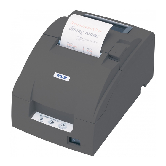
Product Overview Product Overview This chapter describes features of the product. Features TM-U220-i is a receipt printer which can print directly from a smart device application or Web application. This product supports ePOS-Device and ePOS-Print and are capable of controlling POS peripherals or network compatible TM printers. - Page 12 The Epson ePOS SDK is a software development kit that integrates the ePOS-Print SDK and the ePOS-Device SDK. It is recommended that application software developed with the ePOS-Device SDK is migrated to the Epson ePOS SDK. For detail, refer to the Migration Guide included with the Epson ePOS SDK.
-
Page 13: Product Configurations
Chapter 1 Product Overview Product Configurations Bundled items • AC adapter (Model: PS-180) • AC cable * • Roll paper (for operation check) • Ribbon cassette (Model: ERC-38) • Start Here • Manual CD • Power switch cover * May vary based on specifications and region. Options •... -
Page 14: Part Names And Functions
After the product is turned on, it requires about 30 seconds until it is ready to print. Power Switch Cover Install the power switch cover that comes with the TM-U220-i onto the printer to prevent inadvertent changing of the power switch, to prevent tampering, and to improve the appearance of the printer. -
Page 15: Roll Paper Cover / Cover Open Lever
Chapter 1 Product Overview Roll paper cover / Cover open lever When setting or replacing the roll paper, use the cover open lever to open the roll paper cover. Pull the cover open lever to open the roll paper cover. Do not open the roll paper cover during printing or while the autocutter is operating. -
Page 16: Control Panel
Control Panel PAPER OUT LED ERROR LED FEED button POWER LED Name Status Description POWER LED Power is being supplied. Power is not being supplied. ERROR LED Normal operation (online) Immediately after the power is turned on or immediately after a reset (offline). -
Page 17: Interfaces
Chapter 1 Product Overview Interfaces Serial port Ethernet port DC-in connector microSD card slot USB host ports USB device port Drawer kick connector Name Description Drawer kick connector Connects a cash drawer. Ethernet port Connect the LAN cable here to connect to the network. USB host port (Type A) Connects peripherals via a USB interface. - Page 18 DIP switch Turn both DIP switches SW-1 and SW-2 of the intelligent I/F board OFF.
-
Page 19: Status Led
Chapter 1 Product Overview Status LED With the status LED on the rear of the product, you can check the interface board status. Status LED Description On (Green) Operating normally. On (Orange) Starting up. If the status LED is on in orange even after 30 seconds have passed since the printer is turned on, repair is required. -
Page 20: Wired Lan Status Led
Wired LAN Status LED With the Wired LAN Status LED on the rear of the product, you can check the communication status of the product. LED (Yellow) LED (Green) Status Description Green Link established Flashing Transmitting/receiving data Link not established Yellow 100BASE-TX 10BASE-T... -
Page 21: Online And Offline
Chapter 1 Product Overview Online and Offline Online When no events to go offline have occurred, the printer is online and ready for normal printing. Offline The printer automatically goes offline under the following conditions: • During power on (including resetting with the interface) until the printer is ready •... -
Page 22: Error Status
Error Status There are three possible error types: automatically recoverable errors, recoverable errors, and unrecoverable errors. Check the error LED flash code. When connection to peripherals fails, check the status LEDs at the lower rear of the product. Automatically Recoverable Errors Printing is no longer possible when automatically recoverable errors occur. -
Page 23: Unrecoverable Errors
Chapter 1 Product Overview Unrecoverable Errors If the same error occurs again even after turning the power back on, contact your dealer or a Epson service center. Turn off the power immediately when unrecoverable errors occur. CAUTION Error Error description... -
Page 25: Setup
You can utilize "Easy Setup", which enables settings to the TM-i to be made in a simple manner using a USB memory that contains a file of EPSON TMNet WebConfig setting values. For detail, refer the “TM-i series Easy Setup Guide”. - Page 26 Epson ePOS SDK, ePOS-Device XML, ePOS-Print XML Settings for Printer Installing the Product ( page 30) Changing the Paper Width ( page 43) Adjusting the Paper Roll Near-End Sensor ( page 46) Connecting the Product to the Network ( page 50)
- Page 27 Attaching the Power Switch Cover ( page 58) Setting the DIP Switches ( page 59) Setting the Memory Switches ( page 62) Settings for EPSON TMNet WebConfig Network Setting ( page 65) Settings for Server Direct Print ( page 72)
- Page 28 Attaching the Power Switch Cover ( page 58) Setting the DIP Switches ( page 59) Setting the Memory Switches ( page 62) Settings for EPSON TMNet WebConfig Network Setting ( page 65) Settings for Connected Devices ( page 73) Settings for Device Data Notification ( page 82)
- Page 29 Attaching the Power Switch Cover ( page 58) Setting the DIP Switches ( page 59) Setting the Memory Switches ( page 62) Settings for EPSON TMNet WebConfig Network Setting ( page 65) Enabling HTTPS Communication ( page 71) Enabling PHP ( page 70)
-
Page 30: Installing The Product
Installing the Product You can install the printer horizontally on a flat surface (with the paper exit on top). Also, you can hang it on a wall using the included accessories. Horizontal Installation Hanging Installation Take measures to prevent the printer from moving by vibration during paper cutting and when using a drawer. -
Page 31: Hanging The Printer On A Wall
Chapter 2 Setup Hanging the Printer on a Wall To hang the printer on the wall, follow the steps below. Before installation, be sure that the printer and all equipment connected to the printer is turned off. Detach all cables from the body of the printer. Static electricity may cause cut paper to adhere to the printer case. - Page 32 Loosen the detector adjustment screw a little bit by using a tool such as a coin and then loosen the screw gently by hand as until it stops. It must not be removed completely. Detector adjustment screw Remove the two screws of the roll paper guide. Roll paper guide For a model that does not have a roll-paper near-end detector, jump to step 6.
- Page 33 Chapter 2 Setup Rotate the detector lever on the roll paper guide to change its direction. After the direction of the detector lever is changed, be sure that the cable is connected to the connector firmly. Detector lever Cable Tighten the detector adjustment screw. Detector adjustment screw...
- Page 34 Align the hole on the roll paper guide with the hole on the roll paper holder to match your roll paper width and then tighten the screw (3×10). You will not use one of the two screws that have been removed when the roll paper guide is removed.
- Page 35 Chapter 2 Setup Tighten the screw (3×6) to fix the roll paper holder for hanging bracket and the base frame. Tighten the screw (3×10) to fix the roll paper holder for hanging bracket and the roll paper holder.
- Page 36 Check that the brake arm is up. brake arm Do not move the brake arm until the roll paper holder for hanging bracket is attached onto the base frame. Otherwise the arm part will be damaged. Insert the dowel of the cam into the hole of the platen frame. Dowel Hole Platen frame...
- Page 37 Chapter 2 Setup While you make sure the pin of the brake arm is in the groove on the inner side of the cam, rotate the cam along with the surface of the platen frame in the direction indicated by the arrow until it clicks into position. Pin of brake arm Close the printer cover.
- Page 38 Removing the cam While you push the cam through the hole on the platen frame with a pointed tool such as tweezers, rotate the cam in the upper direction to remove it.
- Page 39 Chapter 2 Setup Installing the brackets Turn the printer over and then put it on a packing box as a platform horizontally. Fold this part inside and insert it into holes to assemble the package. Attach the upper bracket to the holes numbered “2” and the lower bracket to the holes numbered “1”using the screws (3×6).
- Page 40 Installing the wall-mount Attach the wall-mount to the wall in the position illustrated to the right (with the area marked A at the top), and fasten securely with ten screws. These screws are not included; please use screws appropriate to the type of wall being used. 48 mm 12 mm or more 84 mm...
- Page 41 Chapter 2 Setup Mounting the printer on the wall Slide the brackets into the slots of the wall-mount, starting with the top bracket. When mounting the printer, make sure that the wall-mount is securely fastened to the wall.
- Page 42 Setting the “Right side up printing” “Right side up printing“ is a printing mode used for printers installed on a wall. Turn on the setting for DIP switch 1-1 (U "Setting the DIP Switches" on page 59). For details about this mode, refer to Guide for TM-U220 right side up printing (U "Software and Manuals"...
-
Page 43: Changing The Paper Width
Setup Changing the Paper Width The TM-U220-i accommodates 76 mm {3"},69.5 mm {2.74"}, 57.5 mm {2.26"} wide paper rolls. Follow the steps below to change the paper width. When changing the paper width, be sure to make the setting for the paper width with the memory switch. - Page 44 Make sure the power supply is disconnected. Open the roll paper cover. Take off the roll paper guide from the printer by loosening the two screws. Roll paper guide Push the roll paper guide on the appropriate width. Roll paper guide position of fixing the screws A: 76 mm width B: 69.5 mm width...
- Page 45 Chapter 2 Setup Tighten the spacer with two screws included with the guide. Roll paper guide Set the memory switch (customize value) for the paper width. (U "Setting the Memory Switches" on page 62).
-
Page 46: Adjusting The Paper Roll Near-End Sensor
Adjusting the Paper Roll Near-End Sensor Below are two situations where a paper near-end sensor adjustment is required. • To adjust the detection position to suit the diameter of the roll paper core used. • To adjust the detection position of the remaining amount of roll paper. ... - Page 47 Chapter 2 Setup Adjust the detector by sliding the lever in the direction shown below. Knob Detector lever #1 setting #2 setting The table below shows the point at which the near-end detector is triggered. Note that this figure is a calculated value, and there may be some variations, depending on the printer. Detector position (attaching point of the Trigger point (included the thickness of paper roll core)
- Page 48 Tighten the detector adjustment screw. Detector adjustment screw Check to be sure that the detecting lever moves freely.
-
Page 49: Installing The Microsd Card
Chapter 2 Setup Installing the microSD Card Install the microSD card into the microSD card slot on the rear of the product. Use a microSD card that has wear leveling functions The microSD card can only be used if the PHP function is enabled. ... -
Page 50: Connecting The Product To The Network
Connecting the Product to the Network For Wired LAN connection Connect the product to a network by a LAN cable via a hub. Insert a 10BASE-T/100BASE-TX LAN cable into the LAN connector until it clicks. When LAN cables are installed outdoors, make sure devices without proper surge protection are cushioned by being connected through devices that do have surge protection. - Page 51 Chapter 2 Setup Connecting the unit directly with the product Install the wireless LAN unit to a USB port of the product. USB port Using the USB extension cable Attach the included rubber cover to the connector of the USB extension cable into which the wireless LAN unit will be inserted, to prevent the unit from coming off.
- Page 52 Connect the USB extension cable to the USB port of the product. If you want to fix the wireless LAN unit, cut the included affixing tape to fit and put on the unit, and fix the unit in a place with good communication.
-
Page 53: Connecting The Peripherals
Connecting the Customer Display For details on connecting the customer display, refer to the "DM-D110/DM-D210 Technical Reference Guide". (U "Software and Manuals" on page Use EPSON TMNet WebConfig to configure customer display settings and perform display tests. "Settings for Connected Devices" on page... -
Page 54: Connecting The Serial Communication Device
For key input devices such as barcode scanners and keyboards, connect a USB cable of a device to the USB port at the rear of this product. Use EPSON TMNet WebConfig to select a device control script and perform communication tests. "Settings for Connected Devices" on page... -
Page 55: Connecting The Cash Drawer
Chapter 2 Setup Connecting the Cash Drawer Using the optional product for TM printer is recommended. If the optional external buzzer is used, you cannot use a cash drawer. Specifications of drawers differ depending on makers or models. When you use a drawer other than specified, make sure its specification meets the following conditions. - Page 56 Drawer Connection Circuitry Drawer kick connector With shielded Drawer kick solenoid +24V Control device Drawer open/close switch Printer side User side [Drawer kick side]...
-
Page 57: Connecting The Ac Adapter
Chapter 2 Setup Connecting the AC Adapter Do not use this product with any voltage other than the specified one. Doing so may lead to fire or electric shock. Make sure the wall socket power supply satisfies the rated voltage requirements of the WARNING power supply unit. -
Page 58: Attaching The Power Switch Cover
Attaching the Power Switch Cover Attaching the enclosed power switch cover prevents inadvertent changing of the power switch and tampering. You can turn the power switch on and off by inserting a sharp-pointed object in the holes in the power switch cover. To detach these covers, also use a sharp-pointed object. -
Page 59: Setting The Dip Switches
Chapter 2 Setup Setting the DIP Switches Various functions can be changed with the DIP switch settings. When you adjust the items, we recommend to confirm the new setting. The confirmation is performed by running a self-test. (U"Self-test Mode" on page 123). - Page 60 DSW2 (DIP Switch 2) : default values Function Print column 42/35 40/33 Reserved (Auto cutter enable/ disable) Reserved Fixed to Off Pin 25 reset signal * Used Not used Reserved Fixed to Off Reserved Fixed to Off Reserved Fixed to Off Reserved Fixed to Off *: Be sure to use the device with DIP switches 2-4 ON.
-
Page 61: Setting Procedure
Chapter 2 Setup Setting Procedure If you need to change settings, follow the steps below to make your changes: Turn off the power while removing the DIP switch cover to prevent an electric short, which can damage the printer. ... -
Page 62: Setting The Memory Switches
Setting the Memory Switches This printer has memory switches as software switches for making a variety of settings. Memory switches include Msw2, Msw 8, Customized values. The Memory switch is available to be changed by two methods: • Memory switch setup mode (U "Memory Switch Setup Mode"... -
Page 63: Customize Value
Chapter 2 Setup Msw 8-5: When Off is selected, a bit of the "roll paper end sensor" in each status that is transmitted from the printer is changed every time the roll paper cover is open or closed. When On is selected, a bit of the "roll paper cover open / close"... -
Page 64: Memory Switch Setup Mode
Memory Switch Setup Mode You can configure the memory switches (customized values) of the printer. ❏ Basic Serial communication condition (Serial communication) * ❏ Receive buffer full release condition (Msw 8-7) ❏ Roll paper width (Customize value) ❏ Cover open status (Msw 8-5) *: This function is disabled on this product. -
Page 65: Network Setting
If no IP address is printed, print a status sheet and check the IP address. 3. Start EPSON TMNet WebConfig Access the address bar of the Web browser on the PC for setting to start EPSON TMNet WebConfig. When SSL is disabled: http://[This product’s IP address]/webconfig/... - Page 66 5. Set up a wireless LAN For a wireless LAN, select the [System Settings] menu and [Wireless], and set the items such as SSID and Security Mode. After setting, click [Apply] at the bottom of the screen. Then the settings are written to the product. If [Apply] is not clicked, the settings are not applied.
-
Page 67: Confirming Network Setting
Chapter 2 Setup Confirming Network Setting You can confirm the network setting with a status sheet or EPSON TMNet WebConfig. Confirming with a status sheet Print a status sheet and check the following items. • Wired TCP/IP Get IP Address ... -
Page 68: Initializing The Network Setting
The time server is disabled and the time difference is initialized to the default value. ❏ Admin Settings - Administrator Information - Password The password required when starting up EPSON TMNet WebConfig is initialized to the default value. EPSON TMNet WebConfig settings other than those listed above are not initialized. - Page 69 Chapter 2 Setup Initialization procedure Load the paper on the product and turn on the product. Push and hold the push button for 10 seconds or longer. The following initialization start message is printed. Press the push button with a thin object such as a tweezers. Push button Do not turn off the power until the initialization is completed.
-
Page 70: Enabling Php
Make sure that the microSD card is installed in the microSD card slot on this product. 2. Start EPSON TMNet WebConfig Access the address bar of the Web browser on the PC for setting to start EPSON TMNet WebConfig. When SSL is disabled: http://[This product’s IP address]/webconfig/PHPSetting... -
Page 71: Enabling Https Communication
Connect this product to a network and turn on the product. 2. Start EPSON TMNet WebConfig Access the address bar of the Web browser on the PC for setting to start EPSON TMNet WebConfig. When SSL is disabled: http://[This product's IP address]/webconfig... -
Page 72: Settings For Server Direct Print
Connect this product to a network and turn on the product. 2. Start EPSON TMNet WebConfig Access the address bar of the Web browser on the PC for setting to start EPSON TMNet WebConfig. When SSL is disabled: http://[This product’s IP address]/webconfig/ When SSL is enabled: https://[This product’s IP address]/webconfig/... -
Page 73: Settings For Connected Devices
In addition, check the device ID to be set for the controlled devices with the system administrator. 3. Start EPSON TMNet WebConfig Access the address bar of the Web browser on the PC for setting to start EPSON TMNet WebConfig. When SSL is disabled: http://[This product’s IP address]/webconfig/ When SSL is enabled: https://[This product’s IP address]/webconfig/... - Page 74 This section briefly explains the setup procedure. 1. Start EPSON TMNet WebConfig Access the address bar of the Web browser on the PC for setting to start EPSON TMNet WebConfig. When SSL is disabled: http://[This product’s IP address]/webconfig/ When SSL is enabled: https://[This product’s IP address]/webconfig/...
-
Page 75: Registering Web Contents
Chapter 2 Setup Registering Web Contents Registering Web contents to this product allows the use of a Web server that is accessed from an input terminal for content distribution. You can periodically update Web contents on this product by using a Web server for distributing Web contents that is separate from this product. -
Page 76: Specifications For When Php Is Enabled
• To access the Web contents registered in this product from an input terminal or other device, the reference URL is different depending on the folder configuration of the zip file as shown below. ➀ When SSL is disabled: http://[This product’s IP address]/index.html ➁... -
Page 77: Verifying The Integrity Of Web Contents With Md5 Files
• Save the md5 file to the same folder as the auto updating file. Check Verification You can check the results of running an automatic update from [Information] - [Web Contents] - [Status of Last Automatic Update] in the EPSON TMNet WebConfig. For detail, refer to "Information - Web Contents" on page... -
Page 78: Registering Web Contents
Connect this product to a network and turn on the product. 2. Start EPSON TMNet WebConfig Access the address bar of the Web browser on the PC for setting to start EPSON TMNet WebConfig. When SSL is disabled: http://[This product’s IP address]/webconfig/... - Page 79 Connect this product to a network and turn on the product. 2. Start EPSON TMNet WebConfig Access the address bar of the Web browser on the PC for setting to start EPSON TMNet WebConfig. When SSL is disabled: http://[This product’s IP address]/webconfig/...
-
Page 80: Settings For Spooler
Connect this product to the network and turn on the power. 2. Start EPSON TMNet WebConfig On the setup computer, enter the following into the address bar of your Web browser to start EPSON TMNet WebConfig. When SSL is disabled: http://This product's IP address/webconfig... -
Page 81: Settings For Print Forwarding
Connect this product to the network and turn on the power. 2. Start EPSON TMNet WebConfig On the setup computer, enter the following into the address bar of your Web browser to start EPSON TMNet WebConfig. When SSL is disabled: http://This product's IP address/webconfig... -
Page 82: Settings For Device Data Notification
Connect this product to the network and turn on the power. 2. Start EPSON TMNet WebConfig On the setup computer, enter the following into the address bar of your Web browser to start EPSON TMNet WebConfig. When SSL is disabled: http://[This product's IP address]/webconfig... -
Page 83: Application Development Information
The method for controlling the printer with your print application will depend on the system structure. Controlling method System Page Epson ePOS SDK The Epson ePOS Controlling printing and peripherals from iOS, SDK is a software development kit Android and Windows applications, and Web page 84 that integrates the ePOS-Print SDK applications. -
Page 84: Epson Epos Sdk
Epson ePOS SDK The Epson ePOS SDK is an SDK for developing iOS, Android and Windows applications, and Web applications. You can use the Epson ePOS SDK to control the printer with simple code. Additionally, you can control customer displays, bar code scanners and other POS peripherals connected to this product, and TM printers connected to the network. -
Page 85: Epos-Device Xml
Chapter 3 Application Development Information ePOS-Device XML ePOS-Device XML is a command system that uses XML to define functions to control various POS peripherals (including this product printer unit) connected to this product. An application creates a request message in XML format and sends it to this product using socket communications. This product executes control on peripherals and returns a response. - Page 86 The package includes: • ePOS-Device XML User’s Manual • Sample program How to obtain Download from our web site.
-
Page 87: Epos-Print Xml
Chapter 3 Application Development Information ePOS-Print XML ePOS-Print XML is a POS printer command system that uses XML to define the main functions for the ESC/POS command system. The application creates a request message in XML format and sends it to this product using HTTP. You can print using this product as well as TM printers on a network. - Page 88 How to obtain Download from our web site.
-
Page 89: Server Direct Print
This function has the following features: • Can acquire print data from three different URLs. Print data can be used in ePOS-Device XML format. • Printable to TM printers on the network via TM-U220-i. The package includes: • Server Direct Print User’s Manual •... -
Page 90: Device Data Notification
Device Data Notification Data from the device can be requested to the Web server to trigger the application. The response generated by the request of this product can include print data in ePOS-Device XML format, device control, and communication box control. This comes with the following features. -
Page 91: Web Server
• Create dynamic Web pages. • Manage user data by saving files and operating database. The Web contents registered on this product can be automatically obtained or updated from a specified URL. Device TM-U220-i 1. Request 2. Data http://-----/index.php Http Server... -
Page 92: Spooler And Print Forwarding
Spooler and Print Forwarding This section explains the print flow determined by whether or not the spooler or print forwarding is set for this product. Printing succeeded (1) Print data Printing failed (2) Print processing Spooler disabled Spooler Disabled operation setting Enabled Spooler enabled Spooling... - Page 93 • (5): When print data can be spooled, [JobID, Print result = true] is stored in the spooler. [JobID, Print result = true] is also returned to the application. • (6): Make the reprint settings (number of times and interval) in EPSON TMNet WebConfig. "Web Service Settings - Spooler - Settings" on page 104) •...
-
Page 94: Epson Epos Sdk
Use an API that acquires job IDs to acquire the print results from the application. For more information on the recommended operation environment for application software, refer to the Epson ePOS SDK User's Manuals. • Server direct print: Return the empty print data specified for the job ID as the response to the print request from this product. -
Page 95: Software And Manuals
Memory Switch Setting Utility Setting Utility memory switches and customized value settings. User's Manual. Epson Monitoring Use to check a list of status for the Epson printers Epson Monitoring Tool User’s Tool connected to the network. Manual You can also update certificates for multiple printers used for WPA-Enterprise in a batch. -
Page 96: How To Get Manuals And Software
Included in the wireless LAN cable set (OT-WL01). Included with the product TM-i series WebConfig Packs an API for setting EPSON TMNet WebConfig API User’s Manual for this product. Using this API, you can set and reference EPSON TMNet WebConfig values from your application. -
Page 97: Epson Tmnet Webconfig
A user name and a password will be required on the authentication screen. Enter “epson” for both the user name and the password. You can change the password on the [Password Setting] screen (U"Admin Settings - Administrator Information - Password"... -
Page 98: General Information
General Information You can check the general information of the TM-U220-i. Item Description Administrator Name Displays the administrator name set by the user. Location/Person Displays the product's installation location set by the user. Firmware Version Shows the TM-i firmware version of the TM-U220-i. -
Page 99: Information - Wired - Tcp/Ip
Chapter 3 Application Development Information Information - Wired - TCP/IP You can check the TCP/IP setting for a wired LAN. Item Description Get IP Address Shows the method of getting the IP address. Set using Automatic Private IP Addressing Shows the APIPA setting. (APIPA) IP Address Shows the IP address set with the wired LAN. -
Page 100: Information - Web Contents
Shows the latest date and time when the web contents were installed on the TM-U220-i automatically. Status of Last Automatic Update Shows the result of the last update of web contents on the TM-U220-i. Information - Time You can check the time setting. -
Page 101: Web Service Settings - Device Admin - Printer
Chapter 3 Application Development Information Web Service Settings - Device Admin - Printer You can set printers or check their operation. This product cannot be deleted from a device. The "device ID" for this product can be changed. (U "Changing Device ID of This Product"... -
Page 102: Web Service Settings - Device Admin - Customer Display
SSL certificate imported to this product is registered in the computer or device. Apply Saves settings to TM-U220-i. Communication speed and other items must be set for this product in order to control the cus- tomer display as an RS232C-compliant serial communication device. Set these items to match the communication conditions of the customer display connected to. -
Page 103: Web Service Settings - Device Admin - Key Input Device
Performs a communication test. When SSL is enabled on this product, make sure that the certificate issued by the signature source certification authority of the SSL certificate imported to this product is registered in the computer or device. Apply Saves settings to TM-U220-i. -
Page 104: Web Service Settings - Device Admin - Search Printer
Set the number of retry times when a print error occurs. When print forwarding is set and an error occurs the set number of times, printing is performed using the print forwarding route. Interval(s) Set the retry interval when a print error occurs. Apply Save settings to TM-U220-i. -
Page 105: Web Service Settings - Spooler - Print Forwarding
Set the printer for the print forwarding location when printing fails on primary printer and secondary printer. Register Save the settings for the print forwarding route to TM-U220-i. Registered Print forwarding routes Display a list of the registered print forwarding routes. -
Page 106: Web Service Settings - Web Contents - Update Settings
Sets whether the server authentication is performed with the registered certificate when accessed through https. Apply Saves settings to TM-U220-i. Web Contents Web Contents Specifies the web content files to register. Manual Update Archive File (*.zip) Upload Registers the specified web contents on the TM-U220-i. -
Page 107: Web Service Settings - Server Access - Direct Print
Sets whether to use the Server Direct Print function or not. Select [Enable] or [disable]. Set ID for the server-side program to identify TM-U220-i when [Server Direct Print] is set to [Enable]. This ID becomes the user ID used for Digest access authentication. -
Page 108: Web Service Settings - Server Access - Status Notification
Sets whether to use the Status Notification function or not. Select [Enable] or [Disable]. Set ID for the server-side program to identify TM-U220-i when [Status Notification] is set to [Enable]. This ID becomes the user ID used for Digest access authentication. The set value will also be passed as an ID parameter value for the form data posted to the server. -
Page 109: Web Service Settings - Server Access - Device Data Notification
Sets whether to use the Device Data Notification function or not. Notification Select [Enable] or [Disable]. Server Set ID for the server-side program to identify TM-U220-i when Acces [Device Data Notification] is set to [Enable]. This ID becomes the user ID used for Digest access authentication. The set value will also be passed as an ID parameter value for the form data posted to the server. -
Page 110: System Settings - Network - Wired
Item Description Link Speed & Duplex Sets the speed of data link layer. Apply Saves settings to TM-U220-i. System Settings - Network - Wired - TCP/IP You can make settings for a wired LAN such as IP address. Item Description Get IP Address Sets the method of getting the IP address. -
Page 111: System Settings - Network - Wireless
Enter the pass phrase of the pre-shared key when [Security mode] is set to "WPA" or "WPA2". Apply Saves settings to TM-U220-i. Initially, Authentication Method is set to Open System and Security Mode is set to None. To ensure security, be sure to change the settings before use. -
Page 112: System Settings - Network - Wireless - Tcp/Ip
Sets the addresses of the DNS server in order of usage when [Acquire DNS Server Address Automatically] is set to [Disable]. Apply Saves settings to TM-U220-i. System Settings - Network - Security - Server Authentication You can register certificates, configure the registered certificates, and delete them in this product. Item... -
Page 113: System Settings - Network - Security - Ssl
Chapter 3 Application Development Information System Settings - Network - Security - SSL You can set the SSL communication settings. Item Description Disable Disables SSL authentication. Remove the Select this checkbox to delete the SSL certificate. certificate Enable Enables SSL authentication. Update the Renews certificates registered to this product. -
Page 114: System Settings - Proxy - Proxy
Sets whether the proxy is used for Device Data Notification. Notification Apply Saves settings to TM-U220-i. System Settings - Time - Time You can set the time for the TM-U220-i. Item Description Time Sets the time. Clicking [Get Time] shows the present time. -
Page 115: Admin Settings - Maintenance - Reset
Chapter 3 Application Development Information Admin Settings - Maintenance - Reset You can reset the network functions and restore the settings for EPSON TMNet WebConfig to the factory default settings. Item Description Reset Restarts the network functions while retaining the network setting values such as IP address. -
Page 116: Php Settings
PHP settings Opening PHP Setting Screen Follow the steps below to open the PHP Setting screen of EPSON TMNet WebConfig. Start up a PC connected to the network. Start up the Web browser, and input the following in the address bar. -
Page 117: Status Sheet
If you keep pressing the button for more than 10 seconds, the network settings are initialized. Information on a status sheet <General Information> Firmware X.XX ePOS-Device X.XX Model TM-U220-i Time yyyy-mm-dd hh:mm:ss GMT+hh:mm <Server Direct Print> Disable <Status Notification> Status Notification Disable <Syslog Storage>... - Page 118 Shows the product’s TM-i firmware version, ePOS- Device version, product’s name, and time. Firmware Shows the product’s TM-i Firmware version. ePOS-Device Shows ePOS-Device Service version. Model Shows “TM-U220-i”. Time Shows the date, the present time, and the time difference. Administrator Name Shows the administrator name. Location/Person Shows the location and the user name.
- Page 119 Chapter 3 Application Development Information Item Description Wireless TCP/IP Shows TCP/IP settings for wireless LAN. Get IP Address Shows the method of getting the IP address. Set using Automatic Private IP Addressing Shows the APIPA setting. (APIPA) IP Address Shows the IP address. Subnet Mask Shows the subnet mask.
- Page 120 Item Description Customer Display Shows the device ID and the following customer display information that is registered in ePOS-Device. Shows whether using the customer display. Communications speed Shows the communication speed. Data bit Shows the data bit. Parity Shows the parity. Brightness setting Shows the brightness of the customer display.
- Page 121 Chapter 3 Application Development Information Item Description Server Direct Print Shows Server Direct Print settings. Shows Enable or Disable of Server Direct Print. Shows ID for the server-side program to identify TM- U220-i. Authenticate Server S h ow s w h e t h e r t h e s e r ve r a u t h e n t i c a t i o n i s performed with the registered certificate when accessed through https.
- Page 122 Item Description Spooler Shows spooler settings. Shows enable/disable for the spooler. Count Shows the number of retry times when printing from the spooler. Interval(s) Shows the retr y inter val when printing from the spooler. Print forwarding Shows the printer forwarding route settings for the spooler.
-
Page 123: Settings Confirmation Mode
Chapter 3 Application Development Information Settings Confirmation Mode In addition to normal printing mode, there is also a self test mode and hexadecimal dump mode to check the various printer settings. Self-test Mode The self test lets you know if your printer is operating properly. It checks the control circuits, printer mechanisms, print quality, control software version, and DIP switch settings. -
Page 124: Hexadecimal Dumping Mode
Hexadecimal Dumping Mode In the hexadecimal dumping mode, the printer prints the data transmitted from a host computer in hexadecimal numbers and their corresponding characters. Starting Hexadecimal Dump Mode Follow the steps below to run this mode. If there is no character corresponding to print data, “.” is printed. ... -
Page 125: Easy Setup
Application Development Information Easy Setup Easy setup is a function that allows you to set the EPSON TMNet WebConfig by simply inserting a USB memory stick and turning on the power. The USB memory stick should contain a file (setting.ini) with the setting values for EPSON TMNet WebConfig and a file with web content. -
Page 126: Checking/Updating Tm-I Firmware
Checking/Updating TM-i Firmware Checking the TM-i Firmware Version • Use "Software" in the status sheet (page • Use "General" in EPSON TMNet WebConfig (page Updating TM-i Firmware You can use the TM-i Firmware Update Tool to do the update. ( U... -
Page 127: Handling
Chapter 4 Handling Handling This chapter describes basic handling of the product. Installing/Replacing the Ribbon Cassette Do not touch the print head during printing or immediately after printing. The print head may be very hot after printing so wait a while for it to cool down before beginning the work. WARNING Print head Be sure to use the specified ribbon cassette. - Page 128 Turn off the product. Open the ribbon cassette cover. Turn the knob on the ribbon cassette two or three times in the direction of the arrow. Confirm the direction of the arrow indicated on the ribbon cassette and then make sure you turn the knob in the same direction.
- Page 129 Chapter 4 Handling Install the ribbon cassette so that the ribbon enters between the print head and platen and then push down on the ribbon cassette until it clicks. Check that the ribbon is not wrinkled or creased. Turn the knob on the ribbon cassette two or three times in the direction of the arrow.
- Page 130 Close the ribbon cassette cover.
-
Page 131: Installing/Replacing The Roll Paper
Chapter 4 Handling Installing/Replacing the Roll Paper Do not open the roll paper cover during printing. The product may be damaged. Do not touch the manual cutter with your hands when installing or replacing the roll WARNING paper. Otherwise, you may be injured because the manual cutter blade is sharp. - Page 132 Insert the roll paper in the correct direction. When using 2-ply roll paper, make sure that the top and bottom sheets are aligned at the paper exit.
- Page 133 Chapter 4 Handling Pull out some paper, and close the roll paper cover. Cut the paper you pulled out.
-
Page 134: Removing A Paper Jam
Removing a Paper Jam Turn the power off. Open the roll paper cover. Remove the jammed paper. When you turn the power off by mistake during the printing operation, the cutter blade may stop in the paper feed line. So the paper may not be fed in the first operation normally when you turn the power on. -
Page 135: Adjusting The Auto Cutter Blade
Chapter 4 Handling Adjusting the Auto cutter blade The auto cutter blade may lock up without returning to the standby position as a result of a paper clip or other object entering inside the printer or a paper jam. Turn off the printer, wait 10 seconds, and then turn the printer back on. -
Page 136: Cleaning The Printer Case
Cleaning the Printer Case Be sure to turn off the printer, and wipe the dirt off the printer case with a dry cloth or a damp cloth. Never clean the product with alcohol, benzine, thinner, or other such solvents. Doing so may damage or break the parts made of plastic and rubber. CAUTION Preparing for Transport Follow the steps below to transport the product. -
Page 137: Appendix
Appendix Appendix Product Specifications Printing method 9-pin serial impact dot matrix Autocutter Cutting method By separated-blade scissors Cutting type Partial cut (one point left uncut) (standard factory settings) Full cut (completely cut off) (optional factory setting) Standards: USB2.0 (High/Full/Low speed) Interfaces USB host port ... - Page 138 Buffers Receive buffer 4K bytes / 40 bytes: selectable NV bit image 128K bytes User NV memory 8K bytes Power supply 24 V DC ±7% Life Mechanism 7.5 million lines (Printer unit) Print head 150 million characters When printing at an average of 2 dots per wire per character. Autocutter 800,000 cuts End of life is defined as the point at which the printer reaches...
-
Page 139: Software Specifications
Appendix Software Specifications Print control Epson ePOS SDK, ePOS-Device XML, ePOS-Print XML, Server Direct Print, Device Data Notification EPSON TMNet WebConfig * Utility Network setting (Ethernet/Wireless LAN) Web contents registration ePOS-Device setting Server Direct Print/Status Notification setting ... -
Page 140: Controllable Peripherals
✔ ✔ ✔ ✔ (TM-i Firmware Ver.4.0 or later) ✔ TM-T20II-i ✔ ✔ ✔ ✔ TM-T82II-i ✔ TM-U220-i The following printers with the UB-E02, UB-E03, UB-R03, or UB-R04 embedded ✔ ✔ ✔ ✔ TM-T88IV ✔ ✔ ✔ TM-T88V ✔ ✔... -
Page 141: Printing Specifications
Appendix Other Device Customer Display DM-D110 Key Input Device Barcode scanner, Keyboard Serial Communication Device Device that has a serial interface, such as a scale, cash recycler or CAT terminal. ePOS-Device SDK provides only an API that sends/receives commands. For control of a serial communication device, you will have to use an application of your own. -
Page 142: Character Specifications
Character Specifications Number of characters Font A (initial setting) Alphanumeric characters: 95 Font B International characters: 48 Extended graphics: 128 × 12 pages. Character structure Font A 9 × 9 Font B 7 × 9 (default) Dot width of Printable area The dot width of the printable area depends on DIP switch setting and paper width as shown in the following table. -
Page 143: Printable Area
Appendix Printable Area 76 mm paper width printing Cutting position (manual cutter) Cutting position (autocutter) 34.9 (6.8) (5.8) 63.4 Maximum 200 dots, 400 positions [Units: mm] All the numeric values are typical. - Page 144 69.5 mm paper width printing Cutting position (manual cutter) Cutting position (autocutter) 34.9 (6.7) (5.8) Maximum 180 dots, 360 positions [Units: mm] 69.5 A l l t h e...
- Page 145 Appendix 57.5 mm paper width printing Cutting position (manual cutter) Cutting position (autocutter) 34.9 (4.2) (5.8) 47.5 Maximum 150 dots, 300 positions [Units: mm] 57.5 All the numeric values are typical.
-
Page 146: Paper Specifications
Paper Specifications Paper Normal paper Paper thickness: 1 sheet: 0.06 to 0.085 mm {0.0024 to 0.0033"} types Weight: 52.3 to 64 g/m2 {14 to 17 lb} (45 to 55 kg/1000 sheets 1091 × 788 mm) Carbon paper Number of copies: Original 1 sheet + one copy sheet Thickness: 0.05 to 0.08 mm {0.002 to 0.0031"} (thickness of one sheet);... -
Page 147: Ribbon Specifications
Black and Red Life Black: 1,500,000 characters Red: 750,000 characters *: These ribbon cassette life numbers are under the EPSON test conditions. Electrical Characteristics AC adapter Input voltage AC 90 V to 264 V (AC 100 V to 240 V) -
Page 148: Environmental Conditions
Acoustic noise (operating) Approximately 64 dB (bystander position) Note: The values above are measured in the Epson evaluation condition. Acoustic noise differs depending on the paper used, printing contents, and the setting values, such as print speed or print density. -
Page 149: External Dimensions And Mass
Appendix External Dimensions and Mass • Width: 160 mm {6.3"} • Depth: 248 mm {5.5"} • Height: 138.5 mm {9.8"} • Mass: Approximately 2.5 kg {5.51 lb} (excluding paper, ribbon, and AC adapter) AC Adapter Input conditions Input voltage (rating): AC 100V to 240V Frequency (rating): 50 to 60 Hz Input current (rating): 1.3A Output conditions *... -
Page 150: Option Specifications
Option Specifications Wireless LAN Cable Set (OT-WL01) Wireless module ELPAP07: 802. 11b/g/n wireless LAN Module (EPSON) Standard IEEE802.11b/g/n (Wi-Fi certificated) SSID 1 to 32 one-byte alphanumeric and numbers Connection mode Ad hoc mode, Infrastructure mode Authentic method, Encryption algorithm Open+WEP , Shared+WEP , WPA-PSK+TKIP , WPA-PSK+AES,...
Need help?
Do you have a question about the TM-U220-i and is the answer not in the manual?
Questions and answers