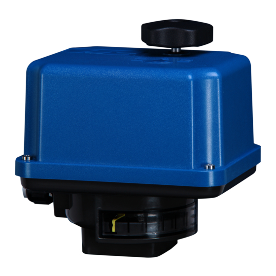
PS Automation PSR-E Series Operating Instructions Manual
Hide thumbs
Also See for PSR-E Series:
- Operating instructions manual (12 pages) ,
- Operating instructions manual (15 pages)
Table of Contents
Advertisement
Quick Links
Advertisement
Table of Contents

Subscribe to Our Youtube Channel
Summary of Contents for PS Automation PSR-E Series
- Page 1 Operating instructions PSR-E Version 2019/08/08 ©2019 PS Automation GmbH...
-
Page 2: Table Of Contents
Contents Technical data ................................... 2 Type key .................................... 2 1. Symbols and safety ............................... 3 2. Usage as per specification ............................. 4 3. Storage ..................................4 4. Operating conditions..............................4 4.1 Installation position ..............................5 5. Function ..................................5 6. Manual operation ................................. 6 7. -
Page 3: Symbols And Safety
1. Symbols and safety Danger signs The following danger signs are used in this operating manual: Caution! There is a general risk of damage related to health and/or properties. Danger! Electrical voltages are present that may lead to death. Life threatening risks may occur due to electrical voltages! Avoid personal or material damages by observing applicable regulations and safety standards! Other notes... -
Page 4: Usage As Per Specification
Ensure that the actuators are always operated in faultless condition. Any damage or faults, and changes in the operational characteristics that may affect safety, must be reported at once. 2. Usage as per specification PSR-E quarter turn actuators are exclusively designed to be used as electric valve actuators. They are meant to be mounted on valves in order to run their motors. -
Page 5: Installation Position
Figure 1: Installation dimensions Outdoor usage: When using actuators in environments with high temperature fluctuations or high humidity, we suggest a heating resistor to be fitted to prevent the build-up of condensation within the enclosure. 4.1 Installation position The actuator can be installed vertically or horizontally or any position in between. -
Page 6: Manual Operation
6. Manual operation The hand wheel allows manual operation in case of power failure or during adjustments (Mounting or positioning the valve). For manual operation, the hand wheel has to be pushed down against a spring. Do not exceed the adjusted electrical stroke limits by using the hand wheel. -
Page 7: Setting Of The Mechanical Stop
8. Setting of the mechanical stop There is one adjustable screw available for setting the mechanical limit of the 90° angular stroke. When setting the mechanical end positions, only the hand wheel may be used. Do not operate the actuator electrically! ... -
Page 8: Setting Of The Internal Limit Switches
9.1 Setting of the internal limit switches Ensure that the mains supply is secured against accidental switching-on! The limit switches are pre-adjusted in the factory. An additional adjustment of the two lower switching cams is normally not necessary. If you wish to adjust the limit switches yourself, please follow the these instructions: ... -
Page 9: Electric Supply
10. Electric supply Switch mains off before starting to work! Connect acc. to wiring diagram on the main frame. Mains connection cables must be dimensioned suitably to accept the maximum current requirement of the actuator and correspond to IEC 227 and IEC 245. The yellow-green coloured cables may be used only for connecting to earth. -
Page 10: Plug On The Hand Wheel
Two adjustable limit switches are installed to limit the stroke of the actuator, and cut-off the motor current in the relative direction. PE Earth connection on housing plate has to be connected! 11. Plug on the hand wheel After wiring and closing of the main cover: Snap the plug for corrosion protection into the recess of the hand wheel. - Page 11 15. CE Declaration of Conformity...
- Page 12 Sytc@HK.Super.net Switzerland www.maxonicauto.com Avintos Flow Control AG Weidenweg 17 India CH-4310 Rheinfelden PS Automation India Pvt Ltd. Phone: <+41>61-83 61-5 30 Srv. No. 25/1, Narhe Industrial Area, Fax: <+41>61-83 61-5 99 A.P. Narhegaon, Tal. Haveli, Dist. E-mail: info@avintos.com IND-411041 Pune www.avintos.com...


Need help?
Do you have a question about the PSR-E Series and is the answer not in the manual?
Questions and answers