PS Automation PSQ103 Operating Instructions Manual
Hide thumbs
Also See for PSQ103:
- Operating instructions (4 pages) ,
- Operating instructions manual (19 pages)

Related Manuals for PS Automation PSQ103


Summary of Contents for PS Automation PSQ103
- Page 1 Operating Instructions PSQx03 Version 01/08/2019 ©2019 PS Automation GmbH Subject to changes!
-
Page 2: Table Of Contents
Contents Type key .................................... 2 1. Symbols and safety ............................... 3 2. Usage as per specification ............................. 4 3. Storage ..................................4 4. Operational conditions ..............................4 4.1 Installation position ..............................5 5. Function ..................................5 6. Manual operation ................................. 6 7. -
Page 3: Symbols And Safety
1. Symbols and safety Dangers of non-compliance with safety regulations PSQx03 actuators are built to state-of-the-art technology and are safe to operate. Despite this, the actuators may be hazardous if operated by personnel that has not been sufficiently trained or at least instructed, and if the actuators are handled improperly, or not used as per specification. -
Page 4: Usage As Per Specification
Other notes The motor surface may have elevated temperature when servicing, inspecting or repairing it immediately after operation. Danger of burning the skin! Always observe the relevant operating instructions when fitting PS accessories or operating the actuator with PS accessories. -
Page 5: Installation Position
The 90° motion is mechanically adjustable by +/- 5° by means of two stop screws. Torque switches are installed for each direction (at PSQ103 and bigger). -
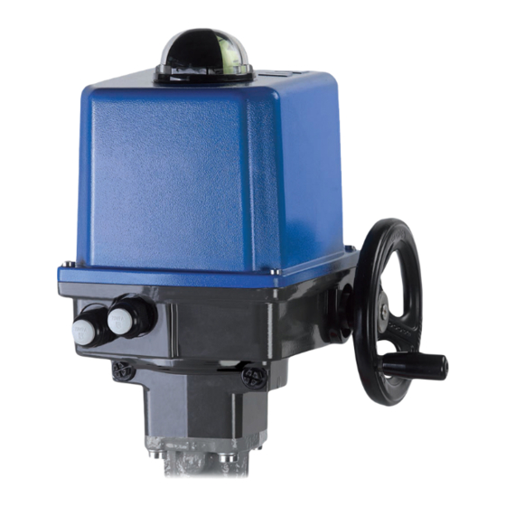
Page 6: Manual Operation
The handwheel does allow comfortable manual operation in case of power failure or for commissioning. The handwheel is idle when the motor is operating the actuator, but engaged in any position without clutching or declutching. Electrical wiring is done to a terminal block under the actuator cover. 6. -
Page 7: Valve Mounting
7. Valve mounting The PSQx03 actuators are provided with a mechanical interface according to ISO 5211 for valve mounting. The „Wolfrom“ gear does contain a removable drive bush to connect the actuator to the valve stem. 1 = actuator flange 2 = drive bushing 3 = indicator tooth ... -
Page 8: Adjustment Of The Position Indicator
8.1 Adjustment of the position indicator The position indicator is a two-coloured half ball turning under a transparent dome with blackened quarter segments. Take off the cover and turn the half ball as appropriate to adjust the position indicator. Figure 7: Adjustment of the position indicator 9. -
Page 9: Setting The Torque Limit
Ensure that the mains supply is secured against accidental switching-on! Run the actuator electrically to the closed position until the valve is closed and the actuator is switched off by the torque switch. Turn the cam of the CLOSE position switch (figure 8, item 1) with an isolated screw driver (4 mm blade width) anti-clockwise until the micro switch is heard to click. -
Page 10: Electric Supply
PSQ103 PSQ203 PSQ503 PSQ703/1003 Mark Torque Mark Torque Mark Torque Mark Torque End position 100% End position 100% End position 100% End position 26100%2 Mark 1 Mark 1 Mark 1 Mark 1 Mark 2 Mark 2 Mark 2 Mark 2... -
Page 11: Wiring Diagram
11.1 Wiring diagram Figure 12 indicates the wiring diagrams for standard actuators. However, the wiring diagram inside the actuator cover is relevant for the specific actuator. See the separate wiring diagram in the corresponding service instructions for any set of accessories. Figure 11: Wiring terminals X0 = Potentiometer, internal wiring... -
Page 12: Commissioning
PE earth connection on housing plate has to be connected! Figure 13: Electrical connection PE Two adjustable position switches are installed to limit the stroke of the actuator, and cut-off the motor current in the relative direction. Most motors have a thermal switch, depending on the actuator type, to cut off the current in both directions when a maximum temperature is reached (only at standard single phase power supply). -
Page 13: Cleaning
13.2 Spare parts PSQx03 actuators are very robust functional units. In case of malfunction or damage of any component, spare parts are available as per a separate spares price list. Please contact PS Automation GmbH or the appropriate representative. Damaged actuators can be returned to our plant in Bad Dürkheim, Germany, or to our representatives, for evaluation of failures and repair. -
Page 14: Declaration Of Incorporation Of Part Completed Machinery And Ec Declaration Of Conformity In Compliance With The Directives On Emc And Low Voltage
14.2 Declaration of Incorporation of Part Completed Machinery and EC Declaration of Conformity in compliance with the Directives on EMC and Low Voltage... - Page 16 Apartado de Correos, 142 E-43480 Vila-Seca (Tarragona) India Phone: <+34> 9 77 39 11 09 PS Automation India Pvt. Ltd. Fax : <+34> 9 77 39 44 80 Srv. No. 25/1, Narhe Industrial Area, E-mail : hans@sertemo.com A.P. Narhegaon, Tal. Haveli, Dist.
Need help?
Do you have a question about the PSQ103 and is the answer not in the manual?
Questions and answers
как связать привод PSQ103 сТРМ-1
PS PSQ103/8 ELECTRIC ACTUATOR, I would like to buy this item