Spectra Logic Spectra nTier700 Installation Manual
Virtual tape library appliance
Hide thumbs
Also See for Spectra nTier700:
- Release note (14 pages) ,
- Supplementary manual (11 pages) ,
- Read this first (2 pages)

Related Manuals for Spectra Logic Spectra nTier700


Summary of Contents for Spectra Logic Spectra nTier700
- Page 1 Spectra nTier700 Virtual Tape Library Appliance Installation Guide PN 90990038 Revision A...
- Page 2 WARRANTIES OF MERCHANTABILITY OR FITNESS FOR A PARTICULAR PURPOSE, BOTH OF WHICH ARE EXPRESSLY DISCLAIMED. In no event shall Spectra Logic be liable for any loss of profits, loss of business, loss of use or data, interruption of business, or for indirect, special, incidental or consequential damages of any kind, even if Spectra Logic has been advised of the possibility of such damages arising from any defect or error.
-
Page 3: High Voltage
Warnings AC Power Warning: Risk of electrical shock. To remove AC power from the Spectra nTier700 VTL, unplug all three of the power cords from the power inlets. Warnung: Gefahr eines elektrischen Schlages. Um den Wechselstrom des Spectra nTier700 VTL abzuschalten, ziehen Sie alle Drei Netzkabel aus den Eingangsbuchsen. - Page 4 Warnings Working with Drives and Blades Warning: Do not operate the nTier700 VTL with the blades pulled out of the enclosure except when servicing the drives. Extending the blades exposes electrical components that pose a potential risk of heat and fire associated with high energy short circuits.
-
Page 5: Contacting Spectra Logic
Contacting Spectra Logic To obtain general information Spectra Logic web Site: www.spectralogic.com United States Headquarters Spectra Logic Corporation 1700 North 55th Street Boulder, CO 80301 Phone: (800) 833-1132 or (303) 449-6400 International: 00 (1) 303 449 6400 Fax: (303) 939-8844... - Page 6 Contacting Spectra Logic Notes...
-
Page 7: Table Of Contents
Conventions Used in This Guide ........13 Chapter 1 – Spectra nTier700 VTL Overview Features . - Page 8 Web Interface Powering-On the Spectra nTier700 VTL ....... . 58 Using the BlueScale Web Interface .
- Page 9 Restarting or Shutting Down the nTier700 VTL ......72 Using the VTL Console ......... . 73 Using the nTier700 VTL RMM .
- Page 10 Storage Capacity ........
-
Page 11: About This Guide
SCSI and Fibre Channel communication protocols, and network connectivity protocols such as Fibre Channel, Ethernet, and iSCSI (Gigabit Ethernet). It also assumes a knowledge of technical tasks such as configuring a Windows Storage Server operating system, installing drivers, and configuring network connections and that you are familiar with installing, configuring, and using data backup and archival software. -
Page 12: Related Publications
The Spectra nTier700 Virtual Tape Library Appliance Release Notes—available on Spectra Logic’s web site—provide the most up-to date information about the nTier 700 VTL, including information about the latest firmware releases. The Implementing nTier Deduplication guide, which is included as a PDF on the... -
Page 13: Conventions Used In This Guide
Provides additional information or suggestions about the current topic. Caution: Provides information you must know to avoid damage to the Spectra nTier700 VTL or to avoid losing data. Warning: Provides information you must know to avoid personal injury. When describing interactions with the BlueScale indicates a series of menu selections. - Page 14 About This Guide Notes...
-
Page 15: Chapter 1 - Spectra Ntier700 Vtl Overview
Spectra nTier700 VTL Overview The Spectra nTier700 Deduplication VTL (referred to as the nTier700 VTL) uses ® FalconStor Virtual Tape Library (VTL) software to provide VTL and Single Instance Repository (SIR) functionality in a single, preconfigured appliance. The nTier700 VTL is available in the following configurations: Spectra nTier700 v1000—A single-blade configuration with 8 Terabytes (TB) of... -
Page 16: Features
RAID storage. Once the data is written to the cache memory, the host can move on to another operation while the data is written to disk. -
Page 17: Components
(HBAs) to provide Fibre Channel or SCSI connectivity to a tape library. High availability. In addition to the RAID 6 protected data storage, batteries provide power to protect the data in the RAID write cache memory for up to 72 hours in the event of a power failure. -
Page 18: Front Panel
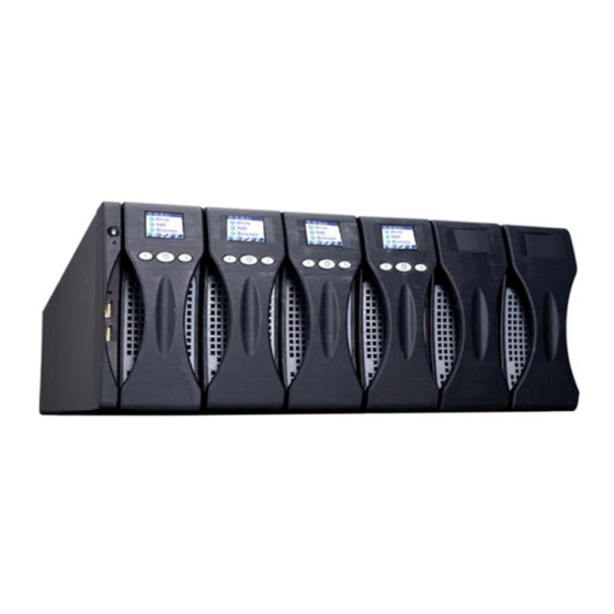
Chapter 1 – Spectra nTier700 VTL Overview Front Panel Figure 1-1 shows the front panel components of the Spectra nTier700 VTL. Chassis management module Power button Standby USB ports (2) Figure 1-1 The nTier700 front panel components (nTier700 v3000 shown). -
Page 19: Rear Panel
Integrated server. The powerful, integrated server uses two high-performance, quad-core CPUs to run the FalconStor VTL software and handle all of the deduplication processing. The dedicated disk storage used by the server is protected by RAID 1 mirroring for high availability. See Integrated VTL Server on page 21 for a detailed description. -
Page 20: Operator Panel
Chapter 1 – Spectra nTier700 VTL Overview Root expanders. Two SAS root expanders connect to the host bus adapters (HBAs) in the server and function to expand the internal SAS bus. Each root expander connects to three blades to provide connectivity to the up to 40 disk drives that can be installed in the nTier700. -
Page 21: Integrated Vtl Server
For security, the operator panel buttons are typically locked through the BlueScale web interface to prevent access to the blades through the operator panel. When the buttons on a blade are unlocked, you can use the operator panel to view the following status information: IP configuration of Ethernet port 1 on the nTier700 VTL server Drive status... - Page 22 Chapter 1 – Spectra nTier700 VTL Overview Serial port (COM2). Not currently used. Ethernet ports. The nTier700 VTL server includes four 1-Gigabit Ethernet (1GbE) ports. Ethernet port 1 provides access to the BlueScale web interface through a standard web browser. The IP address for Ethernet port 1 displays on the operator panel of each blade.
-
Page 23: The Ntier700 Vtl Software
FalconStor Software The FalconStor software provides the Virtual Tape Library (VTL) and Single Instance Repository (SIR) functionality for the Spectra nTier700 Deduplication VTL. For detailed configuration and use information, read the Implementing nTier Deduplication guide, which is included as a PDF on the nTier Deduplication CD. - Page 24 Chapter 1 – Spectra nTier700 VTL Overview Notes...
-
Page 25: Chapter 2 - Installing The Ntier700 Vtl
Installing the nTier700 VTL This chapter describes how to install the Spectra nTier700 VTL at your site. Note: Spectra Logic’s professional installation services will install and configure your Spectra nTier700 VTL according your requirements. Preparing for the Installation on page 26... -
Page 26: Preparing For The Installation
Make sure that access to the installation location is restricted to authorized personnel who are aware of possible safety risks when the blades are extended. The Spectra nTier700 VTL chassis serves as a protective enclosure when the blades are in their normal operating position. Extending the blades exposes electrical components that pose a potential risk of heat and fire associated with high energy short circuits. -
Page 27: Unpacking The Ntier700 Vtl
Unpacking the nTier700 VTL The Spectra nTier700 VTL and its drives are shipped in cardboard boxes attached to pallets. The only tool needed to unpack them is a pair of scissors. Prepare the Unpacking Location Note: Make sure that you have a work space area prepared before you remove the nTier700 VTL from its shipping box. - Page 28 Do not unpack the nTier700 VTL or its drives if the Tip N Tell or Shockwatch indicator has been tripped. Contact both the shipping company and Spectra Logic to report the problem. 4. Use scissors to cut the straps securing the shipping box to the pallet.
- Page 29 6. Remove the accessory box (Figure 2-3), which contains the rack mounting kit, accessories, and documentation and set it aside. Remove the box containing drives and the place it on your work surface. Note: The shipping box contains one box of ten drives for installation in a single blade.
- Page 30 Chapter 2 – Installing the nTier700 VTL 8. Lift the cardboard sleeve surrounding the nTier700 VTL off (Figure 2-4), then remove the protective plastic bag (Figure 2-5). Figure 2-5 Remove the protective foam and plastic bag. 9. Using two people, lift the nTier700 VTL off the pallet and place it on a cart or table sturdy enough to hold the weight.
-
Page 31: Inventorying The Components
Inventorying the Components Each Spectra nTier700 VTL is unique, depending on the specific configuration ordered. At a minimum, the nTier700 VTL includes one fully-populated blade and two power supplies. Note: The blades, blanks, and power supplies you ordered are shipped already installed. -
Page 32: Installing In A Rack
A license key for the nTier Deduplication VTL software documentation Spectra nTier700 Deduplication VTL documentation: Implementing nTier Deduplication Spectra nTier700 Virtual Tape Library Appliance Installation Guide (this guide) Installing in a Rack Install the nTier700 VTL in a standard 4-post, 19-inch rack using 4 units (4U) of rack space. -
Page 33: Before You Begin
Before You Begin Before you install the nTier700 VTL in a rack: Have on hand: #2 Phillips screwdriver, magnetic if available Rack for mounting the nTier700 VTL Measuring tape (recommended) Level (recommended) Identify the location where you will install the nTier700 VTL. Assemble the rack, if necessary. - Page 34 Chapter 2 – Installing the nTier700 VTL 2. Lift the front of the shelf and align the lowest hole in the front mounting tabs with the lowest hole that you want to use on each front post (Figure 2-6). Make sure the tabs are behind the cut-outs in the posts.
-
Page 35: Install The Ntier700 Vtl Into The Rack
Install the nTier700 VTL into the Rack Warning: The nTier700 VTL weighs approximately 134 lb. (60.78 kg) when empty. Enlist at least two people to help lift the nTier700 VTL out of and into the rack. Warnung: Die nTier700 VTL wiegt ca. 60.78 kg, wenn leer. Einstellen mindestens zwei Menschen zu helfen, heben Sie die nTier700 VTL aus und in den Halter. -
Page 36: Unlock The Blades
Chapter 2 – Installing the nTier700 VTL When viewed from the front of the nTier700 VTL, the odd-numbered drives (1, 3, 5, 7, 9) are located on the left side of the blade; the even-numbered drives (2, 4, 6, 8, 10) are located on the right side. -
Page 37: Install The Drives
3. With the screwdriver still in place, pull outward on the chassis management module (Figure 2-8) until you feel it disengage from its internal connector. Caution: Only slide the chassis management module out about 2 inches (5 cm). Do not remove it from chassis. Note: You may need to push down slightly on the screwdriver to lift the latch. - Page 38 1. Put on the provided anti-static wristband and attach it to an unpainted metallic surface. Caution: Any damage to the Spectra nTier700 VTL or its drives caused by failure to protect it from electrostatic discharge (ESD) voids the nTier700 VTL’s warranty. To protect the nTier700 VTL and its...
- Page 39 5. Release the latch on the drive sled by pushing the locking tab to the left, then pulling the latch slightly toward the top of the drive to open it (see Figure 2-10 and Figure 2-11). Note: You only need to pull up on the latch enough to release it. Figure 2-10 Release the drive sled latch.
-
Page 40: Connecting The Cables And Powering On
Chapter 2 – Installing the nTier700 VTL 8. Repeat Steps 4 through 7 to install all of the remaining drives in the blade. 9. Using the blade handle, slide the blade completely into the nTier700 VTL enclosure until it is firmly seated. 10. - Page 41 If required, connect additional Ethernet cables to the remaining Ethernet ports. You configure these network connections after you complete the initial configuration steps (see Configuring Additional Network Connections on page 50). 2. If you plan to use remote power management, connect an Ethernet cable to the RJ-45 RMM port on the rear panel.
-
Page 42: Setting The Ip Address For Ethernet Port 1
Chapter 2 – Installing the nTier700 VTL 6. Press the power button on the left side of the front panel. A blue LED indicates that the power is on, as shown in Figure 2-13. Power button Figure 2-13 The location of the power button. 7. -
Page 43: Use The Blade Operator Panel
Use the Blade Operator Panel Note: You can set the IP address for Ethernet port 1 using the operator panel on any blade. You can also use the VTL Console to set the IP address (see Use the VTL Console on page 44). 1. -
Page 44: Use The Vtl Console
Chapter 2 – Installing the nTier700 VTL 4. Set the IP address, Subnet, and Gateway. a. Press > again to select the Addr tab and press O to select the IP address. b. For each number in the IP address, use > and < to move to select the number in the IP address that you want to change, then press O to select the number. -
Page 45: Configuring The Power Recovery Behavior
Configuring the Power Recovery Behavior Use the following steps to configure how the nTier700 VTL behaves when power is restored following a power loss. Note: You can set the Power Recovery behavior using the operator panel on any blade. Note: If the server BIOS is configured to initiate power recovery, the nTier700 VTL automatically powers on as soon as power is restored, regardless of how you set the Power Recovery option. -
Page 46: Next Steps
Chapter 2 – Installing the nTier700 VTL Next Steps Your nTier700 VTL hardware is installed. Read the following to begin configuring the nTier700 VTL: If you have not already done so, install the VTL Console on a Windows-based computer on the same network as the nTier700 VTL. Read the Implementing nTier Deduplication guide for detailed instructions. -
Page 47: Chapter 3 - Configuring The Ntier700 Vtl
Configuring the nTier700 VTL This chapter describes how to configure your Spectra nTier700 VTL for operation in your environment. Before You Begin Review the Configuration Process on page 48 Accessing the BlueScale Web Interface on page 48 Configuring Additional Network Connections on page 50... -
Page 48: Review The Configuration Process
Chapter 3 – Configuring the nTier700 VTL Review the Configuration Process The following steps summarize the process for configuring the nTier700 VTL for use in your environment. The hardware configuration steps use the BlueScale web interface to the nTier700 VTL. The steps for configuring virtual tape libraries (VTLs) and deduplication use the VTL Console and are described in the Implementing nTier Deduplication guide. - Page 49 Use the following steps to connect to the BlueScale web interface. 1. Open a web browser on a computer connected to the same network as the nTier700 VTL. 2. Enter the IP address for Ethernet port 1 on the nTier700 VTL in the browser address bar using the form https://nnn.nnn.nnn.nnn, where nnn.nnn.nnn.nnn is the IP address.
-
Page 50: Configuring Additional Network Connections
Chapter 3 – Configuring the nTier700 VTL 3. Select “Continue to this website” to ignore the warning and display the main system Overview page (Figure 3-2). Note: The graphic in the BlueScale web interface shows six blades. Only the three left-most blades are used in the nTier700 VTL. 4. - Page 51 Ethernet port 1 is the only port for which you can set the IP address information using the blade operator panel (see Setting the IP Address for Ethernet Port 1 on page 42). The IP addressing for the remaining Ethernet ports is configured using the BlueScale web interface, as described in this section.
-
Page 52: Configuring Remote Power Management
Chapter 3 – Configuring the nTier700 VTL Save Changes 4. Select to save your changes. To cancel your changes, select Cancel. Note: If you change the IP address of the Ethernet port that you are using to connect to the nTier700 VTL BlueScale web interface, you will lose your connection when you save your changes. -
Page 53: Start The Psetup Utility
Start the Psetup Utility Use the following steps to access the Psetup utility used to configure RMM. 1. Make sure that the RMM Ethernet port on the nTier700 VTL back panel (see Figure 1-4 on page 21) is connected to an active network with a computer that can be used to access to RMM on the nTier700 VTL using a standard web browser. -
Page 54: Set The Rmm Ip Address
Chapter 3 – Configuring the nTier700 VTL Set the RMM IP Address If your network does not use DHCP, or if you simply want to use static addressing, use the instructions in this section to set a static IP address for the RMM port. Using a static IP address ensures that you always know the IP address for the RMM port and is highly recommended. -
Page 55: Change The Rmm Super User Password (Recommended)
Change the RMM Super User Password (Recommended) You use the superuser login information when connecting to the RMM to configure and use its features. Use the following steps to change the default superuser name and password. 1. Enter the superuser name in the Super User login field. 2. - Page 56 Chapter 3 – Configuring the nTier700 VTL Notes...
-
Page 57: Chapter 4 - Using The Ntier700 Vtl Bluescale Web Interface
BlueScale Web Interface This chapter describes how to use the BlueScale web interface and the blade operator panels to configure and monitor the Spectra nTier700 VTL appliance. Powering-On the Spectra nTier700 VTL on page 58 Using the BlueScale Web Interface on page 59... -
Page 58: Powering-On The Spectra Ntier700 Vtl
Chapter 4 – Using the nTier700 VTL BlueScale Web Interface Powering-On the Spectra nTier700 VTL To power on the nTier700 VTL, press and hold the front panel power button (Figure 4-1) for two to three seconds or until the button’s LED illuminates. Wait while the nTier700 VTL completes its power-on sequence, which takes about five minutes, depending on the nTier700 VTL configuration. -
Page 59: Using The Bluescale Web Interface
Using the BlueScale Web Interface The BlueScale web interface lets you configure the nTier700 VTL network connections, monitor the status of system components, and energy consumption. The BlueScale web server starts automatically when you power on the nTier700 VTL. After the nTier700 VTL completes its power-on sequence, log into the BlueScale web interface as described in Accessing the BlueScale Web Interface on page 48 and view the main system Overview page. -
Page 60: Menus
Chapter 4 – Using the nTier700 VTL BlueScale Web Interface Menus The Menu panel (shown in Figure 4-2) appears along the left edge of each page. Menu buttons in this panel let you navigate through the available menus to select options. Selecting a menu button expands the menu to display the available options. -
Page 61: Viewing Messages
Icon Meaning Warning. A system component requires attention. Check messages to determine the component. Error. A system component has experienced an error condition. Check messages to determine the component and its error condition. Unknown. The status of the system component cannot be determined. Check messages to determine the component. - Page 62 Pay extra attention to any message flagged with the Warning or Error icon, and follow any recommended steps. Contact SpectraGuard Support if you need help (see Contacting Spectra Logic on page 5). Marking Messages as Read The nTier700 VTL can store hundreds of messages at a time. After you read and resolve...
-
Page 63: Monitoring The Status Of Components
Monitoring the Status of Components The tabs on the Overview page (Figure 4-6) provide an at-a-glance system status. Each tab represents a group of related components. From this screen, you can display more detailed status information for individual components. The ability to monitor components status using the BlueScale web interface is especially useful when your nTier700 VTL is operating in a “lights out”... - Page 64 Chapter 4 – Using the nTier700 VTL BlueScale Web Interface The following table describes the types of status information on each component tab. Shows... Blades Overall status for all blades Status of each blade Status of each drive in the blade Power down option for each drive (see Power Off Using the BlueScale Web Interface on page 79) Fans...
- Page 65 To view the detailed status information for all of the components in a group, click the tab. For example, clicking the red RAID tab in Figure 4-8 changes the graphic to show the components associated with RAID and expands the page to show a list of the components (Figure 4-9).
-
Page 66: Monitoring Energy Consumption
Chapter 4 – Using the nTier700 VTL BlueScale Web Interface Monitoring Energy Consumption The Energy Audit page shows a bar graph of the amount of energy your nTier700 VTL is using. The graph and the information below it lets you monitor the nTier700 VTL’s maximum, average, and the total energy consumption over specific ranges of days and time intervals. -
Page 67: Displaying Network Information
3. Select the time range you want to view from the View pull-down menu: Last 2.5 days (30-minute intervals) Last 5 days (1-hour intervals) Last 10 days (10-hour intervals) Last 30 days (6-hour intervals) 4. Select the units of measure you want to use for the vertical axis (Average Power Consumption) of the graph from the Units pull-down menu: Watts Watts/TB... -
Page 68: Using The Blade Operator Panel
Chapter 4 – Using the nTier700 VTL BlueScale Web Interface Using the Blade Operator Panel The operator panel (Figure 4-12) on each blade populated with drives includes a color LCD screen and three buttons. The buttons let you navigate through the options displayed on the screen and make selections. -
Page 69: Unlocking And Locking Operator Buttons
Unlocking and Locking Operator Buttons Your site’s security policies may require locking the operator panel buttons on the front of each blade. If the buttons are locked, you cannot use the operator panel for tasks such as setting the nTier700 VTL IP address, monitoring the unit, unlocking blades, and powering down drives. -
Page 70: Overview Of The Operator Panel Screens
Chapter 4 – Using the nTier700 VTL BlueScale Web Interface Overview of the Operator Panel Screens The following table shows the main screen for each tab and describes the operations that can be performed from that screen. See Operator Panel Status Icons on page 71 for a description of the status icons. -
Page 71: Operator Panel Status Icons
Enclosure Status (nTier tab) status information about nTier700 VTL enclosure. From this screen, you can do the following: Access the screens to monitor blade status Lock or unlock the blades (see Unlock and Extend the Blade on page 81) Configure how the nTier700 VTL handles a power outage (see Configuring the Power Recovery Behavior on page 45). -
Page 72: Restarting Or Shutting Down The Ntier700 Vtl
Chapter 4 – Using the nTier700 VTL BlueScale Web Interface Icon Meaning Drive initializing. The status of the drive cannot be determined because it is initializing. Check the appropriate operator panel screen and the BlueScale web interface for more information. Drive off. -
Page 73: Using The Vtl Console
Using the VTL Console Use the following steps to shut down the system using the VTL Console. 1. Launch the VTL Console if it is not already running. 2. Right-click on the server name (the nTier700 VTL) in the left pane of the VTL Console to display the context menu of options. - Page 74 Chapter 4 – Using the nTier700 VTL BlueScale Web Interface Notes...
-
Page 75: Chapter 5 - Maintenance
Maintenance This chapter describes how to replace a data drive in the Spectra nTier700 VTL. Replacing a Data Drive If one or more data drives in the nTier are not functioning properly, the Blade tab on the Overview page of the BlueScale web interface is red, indicating an error condition. -
Page 76: Prepare The Work Area
A grounded anti-static wristband An nTier700 VTL data drive A #2 Phillips screwdriver An anti-static bag for the malfunctioning data drive Shipping materials for returning the malfunctioning data drive to Spectra Logic Recommended An anti-static mat Identify the Malfunctioning Drive 1. - Page 77 2. Select the Blades tab on the Overview screen to display status information about the blade components. An error icon appears next to the blade containing the malfunctioning drive. Figure 5-1 The Blades tab when a drive is malfunctioning. 3. Under the Blades heading, select the blade that contains the malfunctioning drive to display the status categories for that blade.
-
Page 78: Power Off The Drive
Chapter 5 – Maintenance 4. Select the Drives category for the blade containing the malfunctioning drive. The category expands to list the drives. The malfunctioning drive is indicated by an error icon and a status of failed (Drive 1-2 in Figure 5-2). Figure 5-2 Drives category with drives listed. - Page 79 Power Off Using the BlueScale Web Interface 1. From the list of drives on the Blades tab, click the Power Down button for the malfunctioning drive (see Figure 5-2 on page 78). The page displays a confirmation message (Figure 5-3). Figure 5-3 Confirmation message when powering down a drive.
- Page 80 Chapter 5 – Maintenance Power Off Using the Operator Panel If for some reason you are unable to power off the drive from the BlueScale web interface, or if you want to disable a drive until you have a replacement, you can use the operator panel on the blade containing the drive.
-
Page 81: Unlock And Extend The Blade
Unlock and Extend the Blade The blades of the nTier700 VTL are automatically locked so that only authorized personnel can pull them out and access the drives. Use the Unlock Blades screen on the operator panel of any blade to unlock all of the blades at once. When the blades are unlocked, you can slide a blade out of the nTier700 VTL enclosure to remove a drive. - Page 82 Chapter 5 – Maintenance 6. Use the < or > buttons on the operator panel to move to the X on either side of the screen, then press the O button to exit the Unlock blades screen and return to the Enclosure Status screen.
-
Page 83: Replace The Drive
The drives used in the nTier700 VTL are mounted on custom drive sleds that provide the mounting and electrical connections required to use them in a blade. Only install drives that you purchase from Spectra Logic into your nTier700 VTL. For assistance, see Contacting Spectra Logic on page 5. - Page 84 Chapter 5 – Maintenance 3. Release the latch on the drive sled by pushing the locking tab to the left, then lift upward on the latch until it is fully extended (see Figure 5-5), extracting the drive from the connector inside the blade. Figure 5-5 Extend the latch fully.
- Page 85 3. Place the drive into the sled so that the drive connectors are positioned at the back of the drive sled and the mounting screw holes are toward the bottom of the drive sled (Figure 5-6). 4. Align mounting holes in the drive with the screw holes in the drive sled. 5.
- Page 86 RAID volume. 5. Using the blade handle, slide the blade completely into the nTier700 VTL enclosure until it is firmly seated. 6. Package the malfunctioning drive and ship it to Spectra Logic as described in RMA Returns on page 89.
-
Page 87: Appendix A - Technical Support
Appendix A – Technical Support This chapter reviews the Spectra nTier700 VTL warranty and Spectra Logic’s repair policies and processes: About SpectraGuard Technical Support, below RMA Returns on page 89 Repair Policy: Warranty on page 90 Limited Warranty on page 91... -
Page 88: Opening A Support Ticket
Opening a Support Ticket You can open a ticket using telephone, e-mail, or the Spectra Logic Web site. 1. Note the problem, including what happened just before the failure occurred. 2. Gather the information you will need to provide to SpectraGuard Technical Support. -
Page 89: Rma Returns
RMA Returns Your SpectraGuard Technical Support representative may ask you to return a problem component to Spectra Logic for servicing. To return a component: 1. Obtain a Return Materials Authorization (RMA) number from a SpectraGuard Technical Support representative. This number identifies the component when it arrives at Spectra Logic. -
Page 90: Repair Policy: Warranty
Appendix A – Technical Support Repair Policy: Warranty Spectra Logic warrants the nTier700 VTL to be in good working order for a period of one full year from the date of shipment from Spectra Logic or an authorized Spectra Logic dealer. Should this product fail to be in good working order at any time during this one-year period, Spectra Logic will, at its option, repair or replace this product at no additional charge except as listed below. -
Page 91: Limited Warranty
The standard warranty for the nTier700 VTL is one year of SpectraGuard Standard service. For more information on SpectraGuard Standard, see SpectraGuard Standard, below. In addition to SpectraGuard Standard, Spectra Logic provides the following upgraded service offerings for the nTier700 VTL: SpectraGuard Classic on page 92... -
Page 92: Spectraguard Classic
SpectraGuard Technical Support staff Monday through Friday from 8:00am to 5:00pm, customer local time zone. An exception to telephone support is Spectra Logic and U.S. nationally recognized holidays. Software and Firmware Updates—Spectra Logic provides updates to software and firmware as they become available. Online Support—Customers have access to SpectraGuard knowledge base and all online documentation. -
Page 93: Requirements For Service
A spare drive can be used to immediately replace a failed drive in the system, restoring full data protection in a timely manner. The drive that had the failure can be returned to Spectra Logic for replacement, as long as it is under warranty or a current support contract. - Page 94 Appendix A – Technical Support Notes...
-
Page 95: Appendix B - Regulatory And Safety Standards
Appendix B – Regulatory and Safety Standards This appendix contains information on the regulatory and safety standards that apply to the Spectra nTier700 VTL. See the following sections for detailed information on each: EU Declaration of Conformity on page 96... -
Page 96: Eu Declaration Of Conformity
Boulder, CO 80301 declare under sole responsibility that the Spectra nTier700 Virtual Tape Library appliance to which this declaration relates, meets the essential health and safety requirements and is in conformity with the EU Directives listed below using the relevant section of the EU standards and other normative documents listed in the following table. -
Page 97: Fcc Notice
The Spectra nTier700 VTL complies with all safety-relevant provisions referring to: Protection against electrical hazards Protection against hazards such as: Mechanical hazards Fire hazards Noise Vibration The safety issues of this information technology equipment type have been evaluated by a government-accredited European third-party organization, such as UL Demko International. -
Page 98: Safety Standards And Compliance
Appendix B – Regulatory and Safety Standards Safety Standards and Compliance The Spectra nTier700 VTL complies product safety standards. IEC 60950-1 First Edition UL 60950-1 First Edition CSA-C22.2 No. 60950-1-03 EN 60950-1 Low Voltage Directive (EU: CE Mark) Waste of Electronic and Electrical Equipment (WEEE) -
Page 99: Appendix C - Specifications
Appendix C – Specifications This appendix provides specifications for the Spectra nTier700 VTL. Storage Capacity, below Integrated VTL server on page 100 Size and Weight on page 101 Power Specifications Environmental Specifications Note: The specifications in this chapter are subject to change without notice. -
Page 100: Deduplication Specifications
Appendix C – Specifications Deduplication Specifications The following table shows the deduplication VTL characteristics for the nTier700 VTL. Parameter VTL size VTL capacity Recommended full backup size Deduplication repository size Logical capacity Retention time, approximate Backup speed Max. number of virtual libraries/drives/ tapes a. -
Page 101: Size And Weight
Size and Weight Parameter Dimensions Height (4U) Width Depth Weight Single 1 TB drive No drives 10 drives (minimum configuration) 30 drives (maximum configuration) a. Specifications are subject to change without notice. b. Includes unit, box, and packaging. c. Weights are approximate. Caution: Do not ship the nTier700 VTL with the drives installed in the blades. -
Page 102: Power Specifications
Appendix C – Specifications Power Specifications This section describes the power specifications for the Spectra nTier700 VTL. Input Power Requirements The following table shows input power requirements for the Spectra nTier700 VTL. Source Input Voltage Input Frequency Current Power Consumption... -
Page 103: Environmental Specifications
The rack should always be installed on hard flooring, such as tile. It should never be installed on carpeted flooring. The Spectra nTier700 VTL is equipped with internal fans as well as temperature sensors that operate the fans as much or as little as is necessary in your data center environment. - Page 104 (15˚ C or more). When the nTier700 VTL is moved from a cold storage environment to a warm operating environment, it must be acclimated in its packaging for at least 24 hours before opening to prevent serious condensation damage from occurring.
-
Page 105: Glossary Of Terms
Glossary of Terms array A group of storage devices (typically hard disk drives) controlled in such a way as to provide higher data transfer rates, higher data availability, and/or data redundancy. An array is typically treated as a single volume by a host operating system. One of the most common uses of arrays is in RAID storage. - Page 106 Glossary of Terms – D controller The control logic in a storage subsystem that performs command transformation and routing, aggregation (RAID, mirroring, striping, or other), high-level error recovery, and performance optimization for multiple storage devices. (SNIA) Acronym for Direct Attached Storage.
- Page 107 200 MB per second over distances of up to 100 meters using copper media or up to 10 kilometers over optical fiber. firmware Software embedded within available on Spectra Logic nTier700 VTL hardware. Firmware can be updated through the ethernet connections and USB ports through USB devices.
- Page 108 HSM software constantly monitors disk capacity and moves data from one storage level to the next based on age, category and other criteria as specified by the network or system administrator.
- Page 109 Light-Emitting Diode. It illuminates when electricity passes through it. logical drive A section of disk storage that is seen by the host operating system as a single physical drive. A logical drive might be located on one or more physical drives.
- Page 110 Network Attached Storage. The name given to dedicated data storage technology which can be connected directly to a computer network to provide centralized data access and storage to users on the network. Network-attached storage consists of hard disk storage, including multi- disk RAID systems for storing data and a server that processes the data and maps file locations to the network-attached device.
- Page 111 Return Materials Authorization. Required by Spectra Logic for the repair or exchange of any covered Spectra Logic nTier700 VTL components.
- Page 112 Glossary of Terms – S Storage Area Network. A SAN is a network environment involving a high speed subnetwork allowing storage devices to be shared. SCSI Small Computer System Interface. SCSI is an interface connection used to connect peripheral devices to computer systems.
- Page 113 (SAN). As the tier number increases, less expensive, slower storage media can be used. Thus, tier 3 in a 3-tier system might contain event-driven, rarely used, or archival data stored on tape.
- Page 114 Glossary of Terms – V virtual disk A virtual disk is a device that provides an area of usable storage capacity on one or more physical disk drives. Virtual disks typically use RAID technology to combine a group of physical disk drives to create a large logical disk.
-
Page 115: Index
Index About menu, description AC power connecting cord and connector types redundancy specifications accessing the BlueScale web interface advanced service options agency declarations EU Directives FCC Notice RoHS WEEE blade blank, description blade operator panel, See operator panel blades description drive slot numbering numbering scheme unlocking... - Page 116 BlueScale web interface expansion slots description location FalconStor VTL Console, See VTL Console fan noise fax numbers for Spectra Logic offices FCC Notice front panel components gateway address setting for Ethernet port 1 setting for Ethernet ports setting for RMM port...
- Page 117 VTL components limited warranty logging in BlueScale web interface security certificate warning logging into RMM mailing address, Spectra Logic media sales, e-mail address menus, on web interface Messages menu, description Messages status icons messages, status deleting description...
- Page 118 Overview page, description parts replacement options SpectraGuard Classic SpectraGuard Premier SpectraGuard Standard password for RMM phone numbers for Spectra Logic offices policies advanced service options warranty repair power cord and connector types input specifications N+1 redundancy...
- Page 119 BlueScale specifications AC power connectors AC power cord data capacity environmental 103, power size and weight VTL server Spectra Logic contacting manuals, obtaining web sites SpectraGuard Support, See technical support standards, safety standby LED, description status displayed on operator panel...
- Page 120 Overview page status icons 60, 60, supported browsers viewing status messages See also BlueScale web interface web sites for Spectra Logic obtaining Spectra Logic manuals WEEE compliance weight nTier700 VTL shipping warnings...
Need help?
Do you have a question about the Spectra nTier700 and is the answer not in the manual?
Questions and answers