Table of Contents
Advertisement
Quick Links
Advertisement
Table of Contents

Subscribe to Our Youtube Channel
Related Manuals for LEMKEN Opal 080 E


Summary of Contents for LEMKEN Opal 080 E
- Page 1 Operating Instructions Mounted Reversible Plough Opal 080 E - en - Item no . 17512540 00/11.18 LEMKEN India Agro Equipment Pvt Ltd. Plot No. D-59, MIDC, Butibori, Nagpur - 441108, Maharashtra, India Phone: +91 - 7104-305400 Fax: +91 - 7104-305444...
- Page 3 However, this brief instruction is not a substitute for thorough study of the operating instructions. These operating instructions will help to familiarise you with the LEMKEN India Agro Equipment Pvt Ltd.device and the options available for using it.
- Page 4 Remember that you should only use genuine LEMKEN spare parts. Reproduction parts have a negative influence on the function of the device, have a shorter ser- vice life and present risks and hazards that cannot be estimated by LEMKEN India Agro Equipment Pvt Ltd. They also increase the maintenance costs.
-
Page 5: Table Of Contents
CONTENTS Allgemeines ....................... 7 Copyright ........................7 Optional accessories ....................7 Symbols used in the Operating Instructions ............8 Hazard classes ......................8 Information........................8 Environmental protection ..................... 8 Indication of passages ....................9 Safety measures and precautions ................. 10 Target group ........................ - Page 6 3.10 Safe use of the implement ..................24 3.10.1 General ........................24 3.10.2 Personnel selection and qualifications ..............25 3.10.3 Hydraulic system ....................26 Handing over the Implement .................. 27 Layout and description ................... 28 Overview ........................28 Description........................29 5.2.1 Headstock ........................
- Page 7 Uncoupling the implement ..................37 Specific safety information..................37 General ......................... 37 10 Driving on public roads ..................40 10.1 Laws and regulations ....................40 11 Operation ......................... 41 11.1 Specific safety information..................41 11.2 Turning the plough frame ................... 41 11.3 Adjusting front furrow width ..................
- Page 8 13 Maintenance and repairs ..................50 13.1 Special safety instructions ..................50 13.1.1 General ........................50 13.1.2 Working under the raised device ................50 13.1.3 Immobilise the implement for maintenance and repairs ......... 51 13.1.4 Working on the hydraulics ..................51 13.1.5 Personnel qualifications ..................
-
Page 9: Allgemeines
Infringements will result in a claim for damages. Optional accessories LEMKEN implements may be equipped with various accessories. The operating instructions below describe both series components and optional accessories. Please note: These accessories will vary depending on the type of equipment. -
Page 10: Symbols Used In The Operating Instructions
Symbols used in the Operating Instructions SYMBOLS USED IN THE OPERATING INSTRUCTIONS Hazard classes The following symbols are used in the Operating Instructions for particularly im- portant information: DANGER Denotes an imminent hazard with high risk, which will result in death or severe physical injury, if not avoided. -
Page 11: Indication Of Passages
Symbols used in the Operating Instructions Indication of passages The following symbols are used for particular passages in the operating instruc- tions: Indicates work steps Indicates enumerations... -
Page 12: Safety Measures And Precautions
Safety measures and precautions SAFETY MEASURES AND PRECAUTIONS General safety instructions for the operator are specified in the chapter entitled «Safety measures and precautions». At the start of some main chapters the safety instructions, which refer to all work to be carried out in this chapter, are listed to- gether. -
Page 13: Safety Features Of The Device
Safety measures and precautions Safety features of the device To protect the operator and the device, the device is equipped with special safety features in accordance with country specific requirements. Always keep all safety devices in working order. Safety and warning signs 3.4.1 General information The implement features all equipment which ensures safe operation. -
Page 14: Position Of Warning Stickers
Safety measures and precautions 3.4.2 Position of warning stickers... -
Page 15: Meaning Of Warning Signs
Safety measures and precautions 3.4.3 Meaning of warning signs Please familiarise yourself with the meaning of the warning signs. The following explanations provide detailed information. Please read and observe the operating in- structions and safety instructions before starting up the implement for the first time. Before carrying out maintenance or repair work, switch off the engine and remove key. -
Page 16: Special Safety Instructions
Safety measures and precautions When the three-point power lift is activat- ed, stay outside of the lifting range of the three-point suspension. Special safety instructions Risk of injury due to non-observance of the currently valid occupational safety guidelines If the currently valid occupational safety guidelines are bypassed WARNING or safety equipment is rendered unusable when handling the de- vice, there is a risk of injury. - Page 17 Safety measures and precautions Risk of injury when freeing casualties When rescuing people trapped or injured by the device, there is a risk of additional serious injury to the casualty if the hydraulic con- nections were not connected according to their colour coding as described in the section entitled "Required hydraulic equipment".
-
Page 18: Danger Areas During Implement Operation
Safety measures and precautions 3.5.1 Danger areas during implement operation Moving danger area The danger area around the implement moves with the implement during operation. The danger area includes the area extending across the entire width (a) of the implement in the direction of tra- WARNING vel. -
Page 19: Residual Risks
Safety measures and precautions Residual risks Residual risks are particular hazards which occur when handling the device and which cannot be eliminated despite a design in accordance with safety require- ments. Residual risks are not usually obvious and may be the source of a potential injury or health hazard. -
Page 20: Operation On Public Highways
Safety measures and precautions Operation on public highways 3.8.1 Lighting system and identification A proper lighting system, identification and equipment must be on the device if it is to be transported on public roads. Further information can be requested from the appropriate authorities. -
Page 21: Axle Loads
Safety measures and precautions 3.8.3 Axle loads Implements mounted to the front and rear three-point linkage must not result in the following being exceeded: permissible gross weight of tractor, permissible axle loads of tractor, the tractor's tyre load-carrying capacities. The tractor's front axle must always be loaded with at least 20 % of the tractor's curb weight. - Page 22 Safety measures and precautions Data from tractor operating instructions Take the following data from your tractor's operating instructions: Abbreviation Data Tractor kerb weight (kg) _______ kg Front axle load (kg) of empty tractor _______ kg Rear axle load (kg) of empty tractor _______ kg Data from implement operating instructions ...
- Page 23 Safety measures and precautions Distance (m) between centre of rear axle and centre _______ m of lower control link Calculation of minimum ballasting value at front G for rear mounting im- V min plement x (c + d) – T x b + (0.2 x T x b) V min...
-
Page 24: Check Before Departure
Safety measures and precautions Calculation of actual rear axle load T H tat H tat V tat Enter the value for the calculated actual rear axle load and the permissible rear axle load as given in the tractor's operating instructions into the table. Tyre load-carrying capacity ... -
Page 25: Correct Behaviour In Road Traffic
Safety measures and precautions Before starting up and operating the implement, check the immediate vicinity around it. No-one must be standing in this area! Ensure that visibility is adequate. Observe permitted axle loads, total weights and transportation dimensions. 3.8.5 Correct behaviour in road traffic ... -
Page 26: Safe Use Of The Implement
Safety measures and precautions Keep all safety instructions and danger warnings on the device in a completely legible state. The affixed safety and warning signs provide important information on safe operation. Comply with them to ensure your safety! Do not alter, retrofit or modify the device, potentially impairing safety, without the approval of the manufacturer. -
Page 27: Personnel Selection And Qualifications
Safety measures and precautions There is a risk of injury in the wider operating area around the implement, e.g. from flying stones. Before operating the hydraulic equipment, ensure that nobody is standing in the danger area. There is a risk of crushing and shearing from power-operated components. -
Page 28: Hydraulic System
Safety measures and precautions 3.10.3 Hydraulic system The hydraulic system is under high pressure. When connecting hydraulic cylinders and motors, ensure that the specified hyd- raulic hose connection is used. When connecting the hydraulic hoses to the tractor hydraulics, make sure that the hydraulic system is depressurised on both the tractor and the implement. -
Page 29: Handing Over The Implement
Handing over the Implement HANDING OVER THE IMPLEMENT As soon as the implement is delivered, ensure that it corresponds with the order package. Also check the type and completeness of any supplied accessories. When the device is handed over, your dealer will explain how it works. ... -
Page 30: Layout And Description
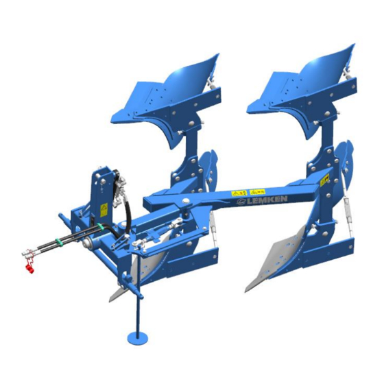
Layout and description LAYOUT AND DESCRIPTION Overview 1 Headstock 5 Plough body 2 Cross shaft 6 Basic frame 3 Stand 7 Turnover device 4 Adjustment centre... -
Page 31: Description
Layout and description Description 5.2.1 Headstock The headstock with top link pin and cross shaft complies with ISO 730. Cross shaft L2/Z2 complies with category 2. The top link pin complies with category 2. 5.2.2 Stand The stand ensures stability when the footing condition deteriorates. 5.2.3 Plough bodies Dural The plough body consists of:... -
Page 32: Turnover Device
Layout and description 5.2.5 Turnover device The ploughs of the Opal 080 series feature the hydraulic turnover device D60. -
Page 33: Preparations On Tractor
Preparations on tractor PREPARATIONS ON TRACTOR Tyres The air pressure must be identical, particularly on the rear tractor tyres. Under dif- ficult conditions, additional wheel weights should be used or the tyres topped up evenly with water. See operating instructions of the tractor manufacturer. Lifting rods The lifting rods should be adjusted so they are as short as possible and of equal length. -
Page 34: Hydraulic Equipment Required
Preparations on tractor Hydraulic equipment required The implement is supplied as standard with separate hydraulic couplings for each consumer. The protecting caps on the hydraulic couplings are coloured and the hydraulic couplings themselves are marked alphanumerically. In order to operate the hydraulic devices, the tractor must be equipped with a double-acting spool valve. -
Page 35: Preparing The Implement
Preparing the implement PREPARING THE IMPLEMENT General Before using the implement for the first time, we recommend that you set it up as described below while you are still in the yard and familiarise yourself with the im- plement and its functions. The settings are adjusted with the implement mounted on the tractor. - Page 36 Preparing the implement Distance between Length of Diameter of Distance, cross shaft and in- drawbar drawbar tractor lower tersection point ex- Tractor power Cat. (shoulder pivot links tension of lower distance) (mm) (mm) links (mm) (mm) 22 - 51 30 - 70 1800 - 2400...
-
Page 37: Attaching The Implement
Attaching the implement ATTACHING THE IMPLEMENT Specific safety information Risk of injury from the parked implement Never enter the danger zone between the tractor and imple- ment. WARNING Read and observe the "Safety measures and precautions" sec- tion and the special safety instructions "Risk of injury from the parked implement". - Page 38 Attaching the implement Connect the top link. The top link should rise up towards the plough while ploug- hing. Secure the top link pin (4). Only use the top link pin supplied with the plough. Switch the tractor's hydraulic system to float position.
-
Page 39: Uncoupling The Implement
Uncoupling the implement UNCOUPLING THE IMPLEMENT Specific safety information Risk of injury from the parked implement Never enter the danger zone between the tractor and imple- ment. WARNING Read and observe the "Safety measures and precautions" sec- tion and the special safety instructions "Risk of injury from the parked implement". - Page 40 Uncoupling the implement Depressurise the hydraulic hoses. See operating instructions from the tractor - manufacturer. Remove the top link from the headstock (1). Disconnect the hydraulic hoses and the electric cables. Install the protecting caps. Position the hydraulic hoses with the couplings between the headstock (1) and the adjusting nut (2).
- Page 41 Uncoupling the implement Unlock the lower link locking device. Remove the lower link from the cross shaft (5). Lower the plough fully. Check that the lower link is completely detached from the cross shaft.
-
Page 42: Driving On Public Roads
Driving on public roads DRIVING ON PUBLIC ROADS 10.1 Laws and regulations All national laws and regulations relating to transport on public roads must be ob- served. -
Page 43: Operation
Operation OPERATION 11.1 Specific safety information Read and observe the "Safety measures and precautions" sec- tion. CAUTION This implement should always be used, operated and repaired by persons who are familiar with it and aware of the risks. ... -
Page 44: Adjusting Front Furrow Width
Operation The turnover device has a double-acting turnover ram (1) with automatic locking and switchover for connection to a double- acting spool valve. Lift the plough completely before turning it. Apply pressure to the hydraulic hose connected to the tractor, marked “P1”. The plough frame turns through 90°. -
Page 45: Angle
Operation 11.4 Angle 11.4.1 General information When ploughing, the base blade should be almost vertical to the ground as seen from the direction of travel. The correct angle is set when the ploughing pattern is uniform. If this is not the case, then the angular adjustment must be altered as described below. -
Page 46: Working Depth
Operation 11.5 Working depth The working depth is set using the tractor hydraulic system. For information on adjusting the hydraulic system, see the operating instructions from the relevant tractor manufacturer. Always switch the hydraulic system to draft control or mixed control. 11.6 DURAL plough body 11.6.1 Angle... -
Page 47: Working Width For Each Body
Operation 11.6.2 Working width for each body The working width for each body is chan- ged using wedges (1) that are screwed between the leg (2) and the frog (3). Three working widths are possible for each body. Narrow side of the wedge (1) points for- wards =>... -
Page 48: Sword Coulter
Operation 11.6.4 Sword Coulter Fit the sword coulter (1) in front of the landslide (2) of the plough body. 11.7 Shearing protection Each plough body is equipped with shea- ring protection (1) to safeguard against overloading. If an excess load is applied to a plough body, the shear bolt (1) shears off. - Page 49 Operation After a shear bolt has broken: Leave the implement in the ground. Carry out the following work on the imple- ment behind the plough body in the direc- tion of travel: Remove the remains of the shear bolt (1).
- Page 50 Operation Install the new shear bolt (1) M12x55 – 10.9. Carefully tighten the shear bolt (1) and the screw (2). See "Tightening torques, page 54".
-
Page 51: Put The Implement Out Of Operation
Put the implement out of operation PUT THE IMPLEMENT OUT OF OPERATION 12.1 Shutting down the implement in an emergency In an emergency shut down the implement via the tractor. Switch the tractor engine off. Remove the ignition key. Damage caused by improper storage of the implement If incorrectly or improperly stored, the implement may be dam- CAUTION... -
Page 52: Maintenance And Repairs
Maintenance and repairs MAINTENANCE AND REPAIRS 13.1 Special safety instructions 13.1.1 General Risk of injury when carrying out maintenance and repair work There is always the risk of injury when carrying out maintenance and repair work. WARNING Use suitable tools, suitable climbing aids, platforms and support elements. -
Page 53: Immobilise The Implement For Maintenance And Repairs
Maintenance and repairs 13.1.3 Immobilise the implement for maintenance and repairs Risk of accidents when tractor starts up Injuries may occur if the tractor starts moving during maintenance and repair work. Switch off the tractor engine before carrying out any work on the WARNING implement. -
Page 54: Protective Equipment
Maintenance and repairs 13.1.6 Protective equipment CAUTION Risk of accident due to working without protective equipment There is always an increased risk of accidents when carrying out maintenance work and repairs. Always wear appropriate protective equipment. 13.1.7 Utilised tool Risk of accident due to use of unsuitable tool WARNING If working with an unsuitable or defective tool, there is a risk of ac-... -
Page 55: Environmental Protection
Replace damaged or faulty hydraulic hoses im- mediately. Hydraulic hoses must be replaced within six years from the date of manufacture. Always use LEMKEN-approved hydraulic hoses. Safety equipment Check that the safety equipment is working pro- perly. See «Safety features of the device, page 11». -
Page 56: Weekly Checks
Maintenance and repairs 13.3.3 Weekly checks Check What needs to be done? Tighten all the bolts and nuts on the implement Bolted connections to the appropriate tightening torque. See «Tightening torques, page 54». If necessary, secure the bolted connections with locking compound. -
Page 57: Bolts And Nuts Made Of Steel
Maintenance and repairs 13.4.2 Bolts and nuts made of steel Strength category Diameter 8.8 [Nm*] 10.9 [Nm*] 12.9 [Nm*] 13,6 16,3 23,4 32,9 39,6 M 10 46,2 64,8 77,8 M 12 80,0 M 14 M 16 M 20 M 24 1112 M 30 1314... -
Page 58: Lubrication Schedule
Maintenance and repairs 13.5.2 Lubrication schedule Every Before and after a long operating hours break Slewing gear bea- rings and cylinder √ √ adapters Bearing tube of the √ √ basic frame Turnbuckles √ Thread of the angu- lar adjustment √... -
Page 59: Troubleshooting
Troubleshooting TROUBLESHOOTING 14.1 Plough penetration and depth control, slippage Fault Cause Solution Retract the body Plough does not stay in Penetration force too low the ground. = Reduce the distance between the point and the frame (not more than 2 cm). ... -
Page 60: Miscellaneous
Troubleshooting 14.2 Miscellaneous Fault Cause Remedy Shear bolt on the base fre- Incorrect shear bolt fitted. Use an original shear bolt. quently shears off. The shear bolt head should always be fitted on the side of the plough that points towards the ploughed land, so that the thread is not in the shearing area. -
Page 61: Technical Data
Technical data TECHNICAL DATA 15.1 Permissible power range and weight Number of Weight Designation Tractor power furrows Approx. kg Opal 080E 30-47 22-35 15.2 Type plate The implement carries a type plate. The type plate can be found at front right on the implement. - Page 62 Technical data 1 Series 2 Type designation 3 Serial number 4 Year of manufacture 5 Permissible drawbar load [kg] 6 Permissible axle load [kg] 7 Permissible gross weight [kg] 8 Company logo and address 9 CE marking (only within the European Union) 10 Name of manufacturer 11 Type, variant, version 12 Type approval date...
-
Page 63: Index
Index INDEX Anglular adjustment..................... 43 Axle loads ......................19 Dural ........................29 DURAL plough body .................... 44 Front furrow width ....................42 Hydraulic equipment .................... 32 Hydraulics ......................31 Maintenance......................50 Pitch angle ......................44 Plough bodies ....................29 Power range ......................59 Preparations on tractor ..................
Need help?
Do you have a question about the Opal 080 E and is the answer not in the manual?
Questions and answers