Table of Contents
Advertisement
Quick Links
Operating Instructions
Mounted Reversible Ploughs
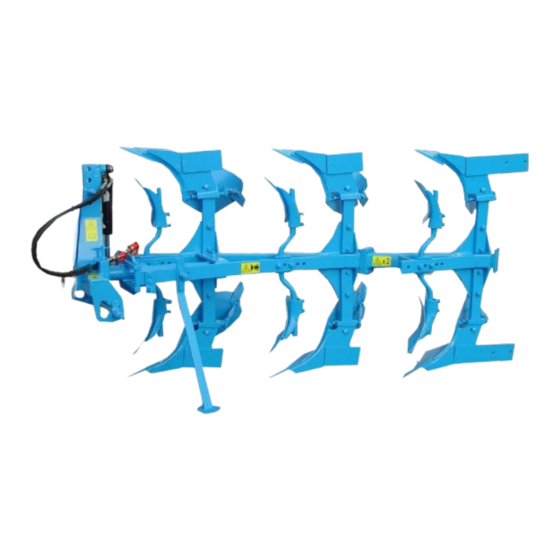
PushPak Opal 90
Safety is our concern!
Part No. 175 3737
GB-1/11.03
LEMKEN GmbH & Co. KG
Weseler Straße 5, D-46519 Alpen / Postfach 11 60, D-46515 Alpen
Telefon (0 28 02) 81-0, Telefax (0 28 02) 81-220
E-Mail: lemken@lemken.com, Internet: http://www.lemken.com
Advertisement
Table of Contents

Subscribe to Our Youtube Channel
Related Manuals for LEMKEN PushPak Opal 90


Summary of Contents for LEMKEN PushPak Opal 90
- Page 1 PushPak Opal 90 Safety is our concern! Part No. 175 3737 GB-1/11.03 LEMKEN GmbH & Co. KG Weseler Straße 5, D-46519 Alpen / Postfach 11 60, D-46515 Alpen Telefon (0 28 02) 81-0, Telefax (0 28 02) 81-220 E-Mail: lemken@lemken.com, Internet: http://www.lemken.com...
- Page 3 Dear customer! We would like to thank you for the confidence in buying this implement. The advantages of this implement will be shown, only, when operated and used with due care and attention. When handing over this implement your dealer has already instructed you with regard to operation, adjustment and maintenance.
-
Page 4: Table Of Contents
Under „defined use“ the manufacturer’s prescribed operation-, maintenance- and repair conditions are to be adhered to! • The PushPak Opal 90 range of ploughs may only be operated, maintained and repaired by such persons who have been made acquainted with it and who have been advised about the dangers! •... - Page 5 PLOUGH ALIGNMENT....................14 6.1 General Instructions ..................... 14 6.2 Front furrow width adjustment ................15 ANGLE ADJUSTMENT ....................16 7.1 General Instructions ..................... 16 7.2 Angle Adjustment with Double Acting Turnover Ram ........16 7.3 Angle Adjustment with Single Acting Connected turnover Ram ..... 16 WORKING DEPTH ADJUSTMENT ................
-
Page 6: Safety Instructions
1 SAFETY INSTRUCTIONS General Safety Instructions • Before using the machine, always check both it and the tractor for roadworthiness and operational safety! • As well as the notes in these instructions the operator is advised to comply with the generally applicable safety at work regulations and those relating to use of the public highway! •... - Page 7 • Regularly check the hydraulic pipes and replace them in the event of damage or signs of ageing. The replacement pipes must comply with the technical specification as laid down by Lemken! • When searching for leaks appropriate aids should be used because of the danger of injury! •...
- Page 8 Maintenance • Repair-, maintenance- and cleaning operations as well as adjustments and remedy of function faults should principally be conducted with engine stopped and brakes applied. Remove ignition key! • Check and tighten nuts and bolts regularly! • When conducting maintenance work on a lifted implement always place suitable supports underneath! •...
-
Page 9: Warning Stickers
2 WARNING STICKERS 2.1 General Instructions The PushPak Opal 90 is equipped with all features to ensure safe operation. Where potential danger areas of the implement can not be fully safeguarded, warning stickers are fitted which draw attention to these. Damaged, lost or unreadable warning stickers must be replaced immediately. -
Page 10: Position Of Warning Stickers
WARNING: Keep well clear of the turning and swinging area of the implement! 390 0520 WARNING: Pinch point! 390 0506 2.3 Position of warning stickers... -
Page 11: Preparation Of Tractor
3 PREPARATION OF TRACTOR 3.1 Tyres Ensure that all are at the manufacturer’s recommended pressures, that left and right hand side tyre pressures are identical and state of wear is approximately the same. For heavy conditions it may be necessary to add wheel weights and/or water ballast. -
Page 12: Axle Load
3.8 Axle load The attachment of implements to the front- and rear-three point linkage must not lead to exceeding the allowed total weight, the allowed axle load and the allowed tyre load of the tractor. The tractor front axle must always be loaded with 20 % of the tractor dead weight at minimum. -
Page 13: Attaching And Detaching The Plough
4 ATTACHING AND DETACHING THE PLOUGH 4.1 Attaching to the Tractor The plough must be parked on level and firm ground and must be attached to the tractor as follows: − Set tractor hydraulics to ‘Position Control’. − Attach lower links to the drawbar (13) and secure. −... -
Page 14: Detaching From The Tractor
4.2 Detaching from the Tractor − Choose a firm, level site. − Turn plough to working position. − Set tractor hydraulics to ‘Position Control’. − Swing down stand (1) and secure. − Lower plough completely. − Stop tractor engine and move spool valve lever to release pressure. −... -
Page 15: Turnover Operation
5 TURNOVER OPERATION 5.1 General instruction The turnover device is equipped with a double acting ram (21) with lock valve and switch over valve for the connection to a double acting tractor spool valve. In connection with a separate return pipe to the oil tank of the tractor it is possible to connect the turnover ram also to a single acting tractor spool valve. -
Page 16: Plough Alignment
6 PLOUGH ALIGNMENT 6.1 General Instructions By means of the selection of the corresponding hole inside the frame carrier (19) the plough frame has to be connected to the headstock by means of the bolt (18), so that the position of the plough frame is adapted to the inner distance of the tractor rear wheels. -
Page 17: Front Furrow Width Adjustment
Type of plough the rear tractor Hole (cm) wheels (cm) Pushpak Opal 90 – 28/55 A60 Pushpak Opal 90 – 28/55 A65 105 - 112 Pushpak Opal 90 – 28/55 A70 Pushpak Opal 90 – 30/60 A60 Pushpak Opal 90 – 30/60 A65 105 - 112 Pushpak Opal 90 –... -
Page 18: Angle Adjustment
7 ANGLE ADJUSTMENT 7.1 General Instructions With the plough in work at the required depth, the legs should be approximately vertical. If not, the angle must be adjusted as follows: 7.2 Angle Adjustment with Double Acting Turnover Ram a) Lift the plough 5 - 10 cm (3 - 4 in). b) Momentarily pressurise port ‘P’... -
Page 19: Working Depth Adjustment
8 WORKING DEPTH ADJUSTMENT The working depth will be adjusted via the tractor hydraulics and the depth wheel of the plough (if fitted). The instructions for the adjustment of the tractor hydraulics can be learned from the instructions of the tractor’s manufacturer. In any case the tractor hydraulics should be set to draft or mixed control. -
Page 20: Adding And Removing A Furrow Extension
9 ADDING AND REMOVING A FURROW EXTENSION The number of furrows of the PushPak Opal 90 can be extended from two to three furrows respectively decreased from three to two furrows. Important: To avoid damages, only one furrow extension (64) may be fitted to the two furrow basic frame (65). -
Page 21: Shearbolt Device
10 SHEARBOLT DEVICE All PushPak Opal 90 are equipped with shearbolts (40) as standard. Replace a broken shearbolt as follows: Raise plough a little and slacken pivot bolt (42). Remove broken sections of old shearbolt (40). Swing body back into position. -
Page 22: Bodies
11 BODIES 11.1 Penetration Angle (pitch) To check correct pitch, measure from plough frame to underside of new point and landside. Frame point measurement should be 1,5 cm (5/8 in) bigger than frame landside. (Measurement A should correspond to the underframe clearance). -
Page 23: Skim Coulters
12 SKIM COULTERS 12.1 General Instructions The universally adjustable skim coulters (65) should be set to a depth between 5 and 10 cm (2 - 4 in) and the tip of the point set to run 2 - 3 cm (3/4 - 1 ¼ in) to the landside of the body. -
Page 24: Trashboards
13 TRASHBOARDS Bolt carrier (78) to the holes provided in the top of the mouldboard (79). Fit trashboard (77) to the carrier and adjust for optimum trash ‘mix’. Adjust support-bolt (80) so that it touches the leg. Secure bolt (80) by means of locknut (81). -
Page 25: Depth Wheel
The PushPak Opal 90 is available with working widths of 28 cm, 30 cm, 33 cm and 38 cm per body. If a PushPak Opal 90 will be delivered with depth wheel, this wheel has already been adapted to the existing working width in the factory. But when the plough will be converted supplementary with a depth wheel, the wheel must be adapted in according to the following drawing. -
Page 26: Maintenance
17 MAINTENANCE All lubrication points must be greased with and environmentally friendly grease. For a long operation break the piston rod of the hydraulic ram must be greased with a non-acid grease. All smooth areas of wearing parts, pins and adjusting devices must be greased regularly. -
Page 27: Failures, Reasons And Remedy
18 FAILURES, REASONS AND REMEDY 18.1 Hydraulic Equipment Failure: Plough frame turns up to the middle position and stops. Reason: The required switchover pressure for the turnover ram has not been reached by the tractor hydraulics. Remedy:a) By means of removing the washers (S) the pre- adjusted switchover pressure will be reduced. -
Page 28: Transport On Public Roads
PUSHPAK OPAL 90 38/113 48/65 21 NOISE, AIRBORNE SOUND The noise level of the PushPak Opal 90 does not exceed 70 dB (A) during work. 22 NOTES As the version of equipment is depending from the order, the equipment of your implement and its description concerned may deviate in some cases.
Need help?
Do you have a question about the PushPak Opal 90 and is the answer not in the manual?
Questions and answers