Table of Contents
Advertisement
Advertisement
Table of Contents

Related Manuals for LEMKEN Opal 090 B


Summary of Contents for LEMKEN Opal 090 B
- Page 1 Operating Instructions Mounted Reversible Ploughs Opal 090 B - en - Item no . 17510578 00/01.15 / LEMKEN India Agro Equipment Pvt Ltd. Plot No. D-59, MIDC, Butibori, Nagpur - 441108, Maharashtra, India Phone: +91 - 7104-305400 Fax: +91 - 7104-305444...
- Page 3 However, this brief instruction is not a substitute for thorough study of the operating instructions. These operating instructions will help to familiarise you with the LEMKEN India Agro Equipment Pvt Ldt.device and the options available for using it.
- Page 4 Remember that you should only use genuine LEMKEN spare parts. Reproduction parts have a negative influence on the function of the device, have a shorter ser- vice life and present risks and hazards that cannot be estimated by LEMKEN India Agro Equipment Pvt Ldt.. They also increase the maintenance costs.
-
Page 5: Table Of Contents
Contents CONTENTS Contents ........................... 3 General information ....................8 Liability ........................... 8 Guarantee ........................8 Copyright ........................9 Optional accessories ....................9 Symbols used in the Operating Instructions ............10 ... - Page 6 Contents 3.9.2 Requirements of the tractor ..................20 3.9.3 Axle loads ........................21 3.9.4 Check before departure ..................... 25 3.9.5 Correct behaviour in road traffic ................26 3.10 Obligation of the operator ..................26 ...
- Page 7 Contents Depth wheel ......................... 37 Skimmer ........................37 Setting the outer screw of the Optiquick adjustment centre ........38 Clearance required for turning ................... 38 Three-point connection....................39 Attaching the implement ..................40 ...
- Page 8 Contents 11.8 Skimmers ........................52 11.8.1 General........................52 11.8.2 Working depth ......................52 11.8.3 Adjusting the projection angle ................52 11.8.4 Lateral position ....................... 53 11.8.5 Forwards or backwards ..................53 ...
- Page 9 Contents 13.3.1 After the initial start-up (at the latest after 2 hours) ..........64 13.3.2 Daily inspection ...................... 64 13.3.3 Weekly inspection ....................65 13.4 Tightening torques ...................... 65 13.4.1 General information ....................65 ...
-
Page 10: General Information
Co. KG, in particular Section IX, shall apply. Liability. In line with the dimensions cited in these conditions the LEMKEN GmbH & Co. KG shall not be held liable for any personal or material damage, when such damage is caused by one or more of the following reasons: ... -
Page 11: Copyright
Infringements will result in a claim for damages. Optional accessories LEMKEN implements may be equipped with various accessories. The operating instructions below describe both series components and optional accessories. Please note: These accessories will vary depending on the type of equipment. -
Page 12: Symbols Used In The Operating Instructions
Symbols used in the Operating Instructions SYMBOLS USED IN THE OPERATING INSTRUCTIONS Hazard classes The following symbols are used in the Operating Instructions for particularly im- portant information: DANGER Denotes an imminent hazard with high risk, which will result in death or severe physical injury, if not avoided. -
Page 13: Indication Of Passages
Symbols used in the Operating Instructions Indication of passages The following symbols are used for particular passages in the operating instruc- tions: Indicates work steps Indicates enumerations... -
Page 14: Safety Measures And Precautions
Safety measures and precautions SAFETY MEASURES AND PRECAUTIONS General safety instructions for the operator are specified in the chapter entitled «Safety measures and precautions». At the start of some main chapters the safety instructions, which refer to all work to be carried out in this chapter, are listed to- gether. -
Page 15: Safety Features Of The Device
Safety measures and precautions Safety features of the device To protect the operator and the device, the device is equipped with special safety features in accordance with country specific requirements. Always keep all safety devices in working order. Safety and warning signs 3.4.1 General information The implement features all equipment which ensures safe operation. -
Page 16: Position Of Warning Symbols
Safety measures and precautions 3.4.2 Position of warning symbols 3.4.3 Meaning of warning signs Please familiarise yourself with the meaning of the warning signs. The following explanations provide detailed information. Please read and observe the operating in- structions and safety instructions before starting up the implement for the first time. - Page 17 Safety measures and precautions Before carrying out maintenance or repair work, switch off the engine and remove key. Do not remain in the operating and swivel area of the implement. Danger of crushing. Keep well clear of the turning and swinging area of the implement.
-
Page 18: Special Safety Instructions
Safety measures and precautions Special safety instructions Risk of injury due to non-observance of the currently valid occupational safety guidelines If the currently valid occupational safety guidelines are bypassed WARNING or safety equipment is rendered unusable when handling the de- vice, there is a risk of injury. -
Page 19: Hazardous Areas
Safety measures and precautions Risk of injury when freeing casualties When rescuing people trapped or injured by the device, there is a risk of additional serious injury to the casualty if the hydraulic con- nections were not connected according to their colour coding as described in the section entitled "Required hydraulic equipment". -
Page 20: Hazardous Areas During Operation Of The Device
Safety measures and precautions 3.6.1 Hazardous areas during operation of the device Residual risks Residual risks are particular hazards which occur when handling the device and which cannot be eliminated despite a design in accordance with safety require- ments. Residual risks are not usually obvious and may be the source of a potential injury or health hazard. -
Page 21: Hazard Caused By Hydraulic Systems
Safety measures and precautions 3.7.2 Hazard caused by hydraulic systems There is a risk of injury to body parts, in particular the face, eyes and unprotected areas of skin, caused by burns and contamination with hydraulic fluid due to hot/pressurised hydraulic fluid spraying out of leaking joints or lines, ... -
Page 22: Requirements Of The Tractor
Safety measures and precautions 3.9.2 Requirements of the tractor Ensure that the tractor with mounted device always reaches the stipulated brak- ing deceleration. Observe the permitted axle loads, gross weights and transportation dimensions, see also section entitled "Axle loads"! Observe the permitted power limit of the tractor! Risk of accidents due to inadequate steerability A tractor which is too small or which has inadequate front ballast... -
Page 23: Axle Loads
Safety measures and precautions 3.9.3 Axle loads Implements mounted to the front and rear three-point linkage must not result in the following being exceeded: permissible gross weight of tractor, permissible axle loads of tractor, the tractor's tyre load-carrying capacities. The tractor's front axle must always be loaded with at least 20 % of the tractor's curb weight. - Page 24 Safety measures and precautions Data from tractor operating instructions Take the following data from your tractor's operating instructions: Abbreviation Data Tractor kerb weight (kg) _______ kg Front axle load (kg) of empty tractor _______ kg Rear axle load (kg) of empty tractor _______ kg Data from implement operating instructions ...
- Page 25 Safety measures and precautions Data to be determined through remeasuring are Determine the following data through remeasuring: Abbreviation Data Distance (m) between centre of gravity for front _______ m mounting implement or front weight and centre of front axle Tractor wheelbase (m) _______ m Distance (m) between centre of rear axle and centre...
- Page 26 Safety measures and precautions Calculation of minimum ballasting value at front G for rear mounting V min implement x (c + d) – T x b + (0.2 x T x b) V min a + b Enter the calculated minimum ballasting value, as required at the front of the tractor, into the table.
-
Page 27: Check Before Departure
Safety measures and precautions Calculation of actual rear axle load T H tat H tat V tat Enter the value for the calculated actual rear axle load and the permissible rear axle load as given in the tractor's operating instructions into the table. Tyre load-carrying capacity ... -
Page 28: Correct Behaviour In Road Traffic
Safety measures and precautions 3.9.5 Correct behaviour in road traffic When driving on public highways, observe the relevant statutory national regu- lations. Driving behaviour, steering and braking performance are influenced by ballast weights. Ensure that the tractor has adequate steering and braking performance. ... -
Page 29: Operating The Device Safely
Safety measures and precautions 3.11 Operating the device safely 3.11.1 General information Before starting work, familiarise yourself with all equipment and actuating ele- ments as well as their functions. Do not operate the device until all protective devices have been attached and are in the safety position. -
Page 30: Personnel Selection And Qualifications
Safety measures and precautions 3.11.2 Personnel selection and qualifications The driver of the tractor must have the appropriate driving licence. Any work on the device may be carried out by trained and instructed personnel only. Personnel must not be on drugs, intoxicated or taking medication. ... -
Page 31: Handing Over The Implement
Handing over the Implement HANDING OVER THE IMPLEMENT As soon as the implement is delivered, ensure that it corresponds with the order package. Also check the type and completeness of any supplied accessories. When the device is handed over, your dealer will explain how it works. ... -
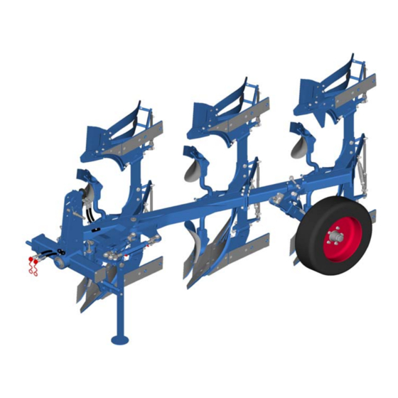
Page 32: Layout And Description
Layout and description LAYOUT AND DESCRIPTION Overview 1 Headstock 8 Additional tools (skimmer, trash- board) 2 Turnover device 9 Disc coulters - not shown 3 Cross shaft 4 Optiquick adjustment centre 5 Basic frame 6 Depth wheel 7 Plough body... -
Page 33: Description
Layout and description Description 5.2.1 Headstock The headstock with top link pin and cross shaft conforms to ISO 730. Cross shaft L2/Z2 conforms to category 2. The top link pin conforms to category 1 + 2. 5.2.2 Turnover device Ploughs in the Opal 090 series are fitted with the hydraulic D65 turnover device. 5.2.3 Optiquick adjustment system The plough line and the front furrow width can be adjusted independently. -
Page 34: Plough Bodies
Layout and description 5.2.6 Plough bodies Dural The plough body consists of: Mouldboard, made up of a shin (1) and a mouldboard (2), or slats (5). Share, made up of a wing (3) and a point (4). Frog (6) ... - Page 35 Layout and description Trashboard (1) Skimmer D1 (2) or M3 (3) Sword coulter (4)
-
Page 36: Disc Coulters
Layout and description 5.2.8 Disc coulters The large, beaded (1) disk coulter provides for a clean furrow. -
Page 37: Preparations On Tractor
Preparations on tractor PREPARATIONS ON TRACTOR Tyres The air pressure must be identical, particularly on the rear tractor tyres. Under dif- ficult conditions, additional wheel weights should be used or the tyres topped up evenly with water. See operating instructions of the tractor manufacturer. Lifting rods The lifting rods should be adjusted so they are as short as possible and of equal length. -
Page 38: Hydraulic Equipment Required
Preparations on tractor Hydraulic equipment required The implement is supplied as standard with separate hydraulic connections for each consumer. The protecting caps on the hydraulic connections are coloured and the hydraulic connections themselves are marked alphanumerically. In order to activate the hydraulic devices, the tractor must be equipped with the following spool valves: Consumer Single-acting... -
Page 39: Preparing The Implement
Preparing the implement PREPARING THE IMPLEMENT General Before using the implement for the first time, we recommend that you set it up as described below while you are still in the yard and familiarise yourself with the im- plement and its functions. The settings are adjusted with the implement mounted on the tractor. -
Page 40: Setting The Outer Screw Of The Optiquick Adjustment Centre
Preparing the implement Setting the outer screw of the Optiquick adjustment centre The outer screw (1) has been set to an ex- treme position to save space during trans- portation. Adjust the outer screw (1) to the approx- imate length of the main link (2). Carry out fine adjustments in the field. -
Page 41: Three-Point Connection
Preparing the implement Three-point connection Loss of the implement The category of the three-point linkage on the tractor and the cat- WARNING egory of the cross shaft and top link pin must correspond, other- wise the cross shaft and top link pin may slip out of the connection when travelling on uneven ground or as a result of vibration. -
Page 42: Attaching The Implement
Attaching the implement ATTACHING THE IMPLEMENT Specific safety information Risk of injury from the parked implement Never enter the danger zone between the tractor and imple- ment. WARNING Read and observe the "Safety measures and precautions" sec- tion and the special safety instructions "Risk of injury from the parked implement". - Page 43 Attaching the implement Connect the top link so that it slopes upwards towards the plough during ploughing work. Secure the top link pin (4). Only use the top link pin supplied with the plough. Switch the tractor hydraulic system to the float position.
-
Page 44: Uncoupling The Implement
Uncoupling the implement UNCOUPLING THE IMPLEMENT Specific safety information Risk of injury from the parked implement Never enter the danger zone between the tractor and imple- ment. WARNING Read and observe the "Safety measures and precautions" sec- tion and the special safety instructions "Risk of injury from the parked implement". - Page 45 Uncoupling the implement Release the pressure from the hydraulic hoses. See the tractor manufacturer's operating instructions. Remove the top link from the plough headstock (1). Disconnect the hydraulic hoses and electrical cables. Fit the protecting caps. ...
-
Page 46: Driving On Public Roads
Driving on public roads DRIVING ON PUBLIC ROADS 10.1 Laws and regulations All national laws and regulations relating to transport on public roads must be ob- served. -
Page 47: Operation
Operation OPERATION 11.1 Specific safety information Read and observe the "Safety measures and precautions" sec- tion. CAUTION This implement should always be used, operated and repaired by persons who are familiar with it and aware of the risks. ... -
Page 48: Setting The Front Furrow Width
Operation The turnover device has a double-acting turnover ram (1) with automatic locking and switchover for connection to a double- acting spool valve. Lift the plough completely before turning it. Apply pressure to the hydraulic hose connected to the tractor, marked “P1”. The plough frame turns through 180°. -
Page 49: Setting The Tractor/Plough Pull Line
Operation 11.4 Setting the tractor/plough pull line Set the tractor/plough pull line using the inner screw (2) so that there is no side pull. Tractor pulls towards the ploughed land: Turn the screw (2) to make it shorter. ... -
Page 50: Inclination Setting (Double-Acting)
Operation 11.5.2 Inclination setting (double-acting) Raise the plough by 5 – 10 cm. Briefly apply pressure to the hydraulic hose which runs to hose connection P on the turnover ram (1). The stop arm (2) rotates a few centime- tres away from the stop. -
Page 51: Working Depth
Operation nation required. Raise the plough completely. Turn the plough completely. Turn the plough back after 3–6 seconds. Lower the plough. Check whether the setting is correct. If not, repeat the adjustment process de- scribed above. -
Page 52: Working Width Per Body
Operation The bodies are mounted with the contact angle central to the ground. The contact angle can be changed with the adjusting screw (1) if required. Adjust the adjusting screw (1). Larger contact angle, notch (4) => better heeling. ... -
Page 53: Tail Pieces
Operation If wedges (1) are used on the plough, a counter-wedge (6) must be fitted between the depth wheel bracket (4) and the plough frame (5) to adjust the alignment of the depth wheel. 11.7.3 Tail Pieces The tail pieces (2) being positioned at the end of the mouldboards (1) should be ad- justed so that they help to turn the furrow slice. -
Page 54: Skimmers
Operation 11.8 Skimmers 11.8.1 General The skimmers (1) should penetrate ap- proximately 5 - 10 cm deep into the soil and, when viewed from above, should ex- tend approximately 2 - 3 cm beyond the side of the share line. 11.8.2 Working depth ... -
Page 55: Lateral Position
Operation 11.8.4 Lateral position Loosen the nut (3). Swivel the round stalk (4) until the skimmer (1) extends approx. 2 – 3 cm beyond the side of the plough body shin. Tighten the nut (3), see «Tightening tor- ques, page 65». -
Page 56: Trashboard
Operation 11.8.6 Trashboard The bracket has slots (6) which allow universal adjustment. Bolt the trashboard (1) with bracket (2) onto the mouldboard (3). The support bolt (4) supports the trash- board against the leg. Secure the support bolt (4) by tightening the lock nut (5). -
Page 57: Disc Coulters
Operation 11.10 Disc coulters 11.10.1 General The disc coulters should operate at a depth of approximately 7 - 9 cm and should run approximately 2 - 3 cm to the side of the vertical shin. 11.10.2 Working depth To adjust the working depth of the disc coulter: ... -
Page 58: Moving The Disc Coulter Forwards Or Backwards
Operation 11.10.3 Moving the disc coulter forwards or backwards Loosen the nuts (4). Loosen the eccentric sleeves (5). Move the bracket (6) forwards or back- wards. The round stalk (7) can also be moved in- side the bracket (6). Two fixing options (C) and (D) are provid- 11.10.4 Disc coulter inclination... -
Page 59: Depth Control Wheel
Operation Never reverse the tractor and implement while the disc coulters are still in the soil. 11.11 Depth control wheel 11.11.1 General The plough can be supplied with a depth control wheel (1). The depth control wheel (1) only has a depth control function. -
Page 60: Working Depth Adjustment
Operation 11.12 Working depth adjustment Adjust the working depth using the screw (3). Turn the screw (3) to make it shorter => increases working depth Turn the screw (3) to make it longer => reduces working depth If the adjustment range of the screw is in- adequate, the working depth can also be set using the bolts (4). -
Page 61: Shearing Protection
Operation 11.13 Shearing protection There are pinch and shear points in the area around the shearing protection. DANGER Never stand in the plough body trip zone while ploughing is tak- ing place. The plough bodies trip upwards when the shear bolt is overload- ... -
Page 62: Put The Implement Out Of Operation
Put the implement out of operation PUT THE IMPLEMENT OUT OF OPERATION 12.1 Shutting down the implement in an emergency In an emergency shut down the implement via the tractor. Switch the tractor engine off. Remove the ignition key. Damage caused by improper storage of the implement If incorrectly or improperly stored, the implement may be dam- CAUTION... -
Page 63: Maintenance And Repairs
Maintenance and repairs MAINTENANCE AND REPAIRS 13.1 Special safety instructions 13.1.1 General Risk of injury when carrying out maintenance and repair work There is always the risk of injury when carrying out maintenance and repair work. WARNING Use suitable tools, suitable climbing aids, platforms and support elements. -
Page 64: Immobilise The Implement For Maintenance And Repairs
Maintenance and repairs 13.1.3 Immobilise the implement for maintenance and repairs Risk of accidents when tractor starts up Injuries may occur if the tractor starts moving during maintenance and repair work. Switch off the tractor engine before carrying out any work on the WARNING implement. -
Page 65: Protective Equipment
Maintenance and repairs 13.1.6 Protective equipment CAUTION Risk of accident due to working without protective equipment There is always an increased risk of accidents when carrying out maintenance work and repairs. Always wear appropriate protective equipment. 13.1.7 Utilised tool Risk of accident due to use of unsuitable tool WARNING If working with an unsuitable or defective tool, there is a risk of ac-... -
Page 66: Environmental Protection
The hydraulic hoses must be replaced at the latest 6 years after the date of manufacture. Use hydraulic ho- ses authorised by LEMKEN only. Safety equipment Check that the safety equipment functions properly. -
Page 67: Weekly Inspection
Maintenance and repairs 13.3.3 Weekly inspection Check What to do? Wheel nuts Check that all wheel nuts are tight and, if re- quired, retighten the wheel nuts to the appro- priate torque. Screw connections Retighten all other bolts and nuts on the device to the appropriate torque. -
Page 68: Bolts And Nuts Made Of Steel
Maintenance and repairs 13.4.2 Bolts and nuts made of steel Strength category Diameter 10.9 12.9 [Nm*] [Nm*] [Nm*] 13,6 16,3 23,4 32,9 39,6 M 10 46,2 64,8 77,8 M 12 80,0 M 14 M 16 M 20 M 24 1112 M 30 1314 1850... -
Page 69: Tyre Pressure
Maintenance and repairs 13.5 Tyre pressure DANGER Too high a tyre pressure can cause the tyres to burst and too low a tyre pressure can result in overloading of the tyres. The tyre pressure shown below is permitted, depending on tyre size, tread and PR number or load index. -
Page 70: Electrical Connections
Maintenance and repairs 13.6.2 Electrical connections Carry out a visual inspection of the plugs and cables. Look for bent or broken contact pins on the plugs and exposed areas on the cables. Apply anti-corrosion spray to the electrical contacts. Faulty plugs or cables must be repaired or replaced immediately by a specialist workshop. -
Page 71: Lubrication Chart
Maintenance and repairs 13.6.3 Lubrication chart Every Before and after a long operating hours winter break Turnover device bearing pivots Optiquick adjustment centre Turnbuckles Swivelling axes on depth wheel Depth wheel bearing Disc coulter bearing Screw thread of the inclination adjust- ment device... -
Page 72: Troubleshooting
Troubleshooting TROUBLESHOOTING 14.1 Hydraulic equipment Fault Cause Solution Fit Plough rattles during the first Plough frame is moving smaller stage of turning. ahead, a vacuum is cre- throttle ated in the turnover ram. turnover connection (T). - Page 73 Troubleshooting Fault Cause Solution Plough frame turns as far as the The tractor hydraulics are The preset switch- middle position and stays there. not reaching the switch- over pressure can over pressure needed for be reduced by re- the turnover ram. moving the washers (U).
- Page 74 Troubleshooting Fault Cause Solution Increase the pre- The pre-set switchover set switchover pressure is too low. pressure by fit- ting additional washers (U). The plough frame turns but the turnover ram switches over be- fore reaching the half-turned position and the plough frame ...
-
Page 75: Plough Intake And Depth Control, Slippage
Troubleshooting 14.2 Plough intake and depth control, slippage Fault Cause Remedy Plough does not remain in the Intake force too low. Pull in the base = Reduce ground. the distance between the share tip and the plough frame (not more than 2 cm). ... -
Page 76: Technical Data
Technical data TECHNICAL DATA 15.1 Permissible power range and weight Number of Weight Description Tractor power furrows kg (approx.) Opal 090 30-45 22-33 Opal 090 2 + 1 45-60 33-44 Opal 090 55-70 40-51... -
Page 77: Identification Plate
Identification plate IDENTIFICATION PLATE The identification plate (1) is situated on the front of the three-point tower. -
Page 78: Index
Index INDEX Additional tools ..................... 32 Adjusting the projection angle ................52 Angular adjustment ....................47 Axle loads ......................21 Contact angle ....................... 49 Depth control wheel ....................57 Depth wheel ......................37 Disc coulters ......................55 Dural ........................32 DURAL plough body ..................... - Page 79 Index Trashboard ......................54 Tyre pressure ....................... 67 Tyres ........................67 UNCOUPLING ...................... 42 Warning signs ....................... 13 Working depth ...................... 49 Working depth adjustment ..................58...
Need help?
Do you have a question about the Opal 090 B and is the answer not in the manual?
Questions and answers