Table of Contents
Advertisement
Quick Links
Installation & Operations Manual
Manual 1189331 Rev 0 (02/07)
$30..00
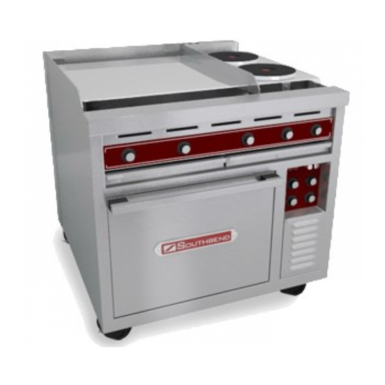
Oven Range
Model SE36
IMPORTANT FOR FUTURE REFERENCE
Please complete this information and retain
this manual for the life of the equipment:
Model #: _________________________
Serial #: _________________________
Date Purchased: _________________
Oven Range
Advertisement
Table of Contents

Related Manuals for Southbend SE36


Summary of Contents for Southbend SE36
- Page 1 Installation & Operations Manual Manual 1189331 Rev 0 (02/07) $30..00 Oven Range Model SE36 IMPORTANT FOR FUTURE REFERENCE Please complete this information and retain this manual for the life of the equipment: Model #: _________________________ Serial #: _________________________ Date Purchased: _________________...
- Page 2 This page intentionally left blank Page I Installation & Operations Manual 1189331 Rev 0 (02/07)
- Page 3 OTHER FLAMMABLE VAPORS AND LIQUIDS IN THE VICINITY OF THIS OR ANY OTHER APPLIANCE. In case of fire, de-energize the Oven Range at its main discon- nect switch/circuit breaker. Switching OFF the power to the Oven Range allows it to cool, making it easier to extinguish a fire.
-
Page 4: Table Of Contents
D. Elecrtical Connection ... 11 E. Initially Cleaning the Griddle and/or Hot Plates ... 11 F. Testing the Installation ... 12 G. Marine Oven Range Installation On Curb ... 12 H. Dimension Drawings ... 13-14 SECTION 3 OPERATION ... 15 I. -
Page 5: Description
I. Description Southbend Model SE36 electric oven ranges are rated heavy duty for commercial use. The oven range consists of a range top fastened to an oven base. There is a marine kit available which qualify it for shipboard use. The marine features are an oven door latch, grease tray latch, bolt-down legs , range top adjustable sea rails and a grab bar across the front. -
Page 6: Range
Section 1 - Description B. RANGE The range can consist of up to 3 different components and the components can be configured in six ways. Troughs with drip chutes are located at the front and rear for draining into two wide drawer type receptacles 1. - Page 7 12”x24” Hot Plate for stock pot cooking (Not recommended for griddling). The hot plates are thermo- statically controlled and have a temperature range of 250 F (204 C) in 12 minutes c. Round Hot Plate for stock pot cooking. The twin hot plates have a 9” diameter and are controlled by 3- heat (low, medium, high) switches.
- Page 8 Section 1 - Description 2. Range Top Configurations a. All purpose TOP SE36D/A-HHH. The all purpose top consists of three 12”x 24” hot plates. The all purpose top is not recommended for griddling b. Multi-Purpose Top SE36D/A-HHB The multi purpose top consists of two 12”x 24” hot plates and two 9”...
- Page 9 c. Griddling Top SE36D/A-TTT. the griddle top consists of one 36”x24” griddle plate. d. Round Hot Plate Top SE36D/A-BBB. The round hot plate top consists of six 9” hot plates. Installation & Operations Manual 1189331 Rev 0 (03/07) Figure 1-7 Griddle Top Figure 1-8 Round Hot Plate...
- Page 10 Section 1 - Description e. Griddle/Round Hot Plate Top SE36D/A-TTB. The griddle/round hot plate top consists of one 24”x24” griddle and two 9” round hot plates. f. Griddle 12”x24” Hot Plate Top SE36D/A-TTH. The griddle 12” x 24” hot plate top consists of one 24”...
-
Page 11: Specifications
---------- Stainless Steel Front Sides and Top ---------- ---------- Aluminized Steel Back ---------- Refer to Section 5 NOTICE Southbend (Manufacturer) reserves the right to change specifications and product design without notice. Such revisions do not entitle the buyer to corresponding changes, improvements, additions or replacements for previously purchased equipment. - Page 12 Section 1 - Description NOTES Page 8 Installation & Operations Manual 1189331 Rev 0 (03/07)
-
Page 13: Section 2 Installation
SECTION 1 INSTALLATION A. Inspect for Shipping Damage All shipping containers should be examined for damage before and during unloading. This equipment was carefully inspected and packaged at the factory. the freight carrier has assumed responsibility for its safe transit and delivery. If equipment is received in damaged condition, either apparent or concealed, a claim must be made with the delivering carrier. -
Page 14: Installationof Oven Range
B. Inspect of Oven Range The oven range can be shipped assembled or the range top module and the oven can be packed in separate cartons. If the oven range is shipped assembled simply remove the metal banding straps and packing materi- als and move it to the permanent location. -
Page 15: Assembling Of Oven Range
C. Assembling (Stacking) the Oven Module and Range Module 1. Move the range top module and the oven module to the area of their permanent location as directed in the previous Paragraph “B” or the Pre-installation Instructions on the outside of the shipping carton. -
Page 16: Testing The Installation
2. Turn main power disconnect switch to ON 3. Check range top components by turning on one control at a time starting at the left side of the control panel. Check that the component is starting to heat and then turn it off. -
Page 17: Dimension Drawings
Section 2 - INSTALLATION H. Dimension Drawings Figure 2-4 Installation & Operations Manual 1189331 Rev 0 (03/07) Page 13... - Page 18 Section 2 - INSTALLATION Figure 2-5 Page 14 Installation & Operations Manual 1189331 Rev 0 (03/07)
-
Page 19: Section 3 Operation
Deck Oven has a heating element at both the top and bottom of the oven cavity. B. OVEN CONTROL PANEL - All Oven operating controls and indicators. C. RANGE TOP - Configured six different ways which consist of griddle, round hot plate, and/or 12” x 24” hot plate. -
Page 20: Control Functions And Location
Section 3 - OPERATION II. Control Functions and Locations A. Convection Oven Control Panel 1. Temperature Thermostat Control - adjustable from 150°F to 450°F(65°C to 232°C). The thermostat is also provided with ON/OFF position. The oven will preheat to 450°F(232°C) in 15 minutes. 2. - Page 21 B. Deck Oven Control Panel 1. Temperature Thermostat Control - adjustable from 200°F to 500°F(93°C to 287°C). The thermostat is also provided with ON/OFF position. The oven will preheat to 450°F(232°C) in 20 minutes. 2. Upper and Lower Heating Element Switches - are 3 position switches which adjust the heating elements at low, medium or high.
- Page 22 3. Round Hot Plate is controlled by a 3-heat switch. The switch positions are LOW, MEDIUM, HIGH and OFF. Adjacent green light is always on while hot plate is on. Page 18 Installation & Operations Manual 1189331 Rev 0 (03/07) Figure 3-4 Range Top with Griddle Control Figure 3-5 Range Top with Hot Plate Control...
-
Page 23: Operation
III. Operation A. Convection Oven Operation 1. Set temperature control knob to the desired tenperature. 2. Push the oven power switch to the ON position. 3. Push the fan switch to the HIGH or LOW position. The LOW fan speed should be used for delicate products or products with loose toppings such as pepperoni on a pizza. - Page 24 Section 3 - OPERATION B. Deck Oven Operation 1. Set temperature control knob to the desired temperature. 2. Turn both Upper and Lower element switches to HIGH. 3. Allow oven to preheat to the set temperature. The amber signal light will remain on until the set tem- perature has been reached.
- Page 25 C. Griddle Operation IMPORTANT: Do not turn griddle on before seasoning procedure has been completed. IMPORTANT: If your griddle is new you must remove the rust preventative material before turning the griddle on. Refer to Section 2, Installation, Paragraph E. 1.
- Page 26 Also wash out grease drawers with hot water and a mild detergent. Wipe dry and replace in range. NOTE: Marine ranges are equipped with a grease drawer latch which must be held depressed as the grease drawers are removed.
- Page 27 Marine ranges are provided with a full width grab bar, 6” marine bolt down legs, and oven door latch and sea rails to prevent movement of pots on range top. The range top sea rails may have to be repositioned when various size pots or vessels are used. Installation & Operations Manual 1189331 Rev 0 (03/07)
-
Page 28: Time And Temperature Charts
Section 3 - OPERATION IV. Time and Temperature Charts DECK OVEN BAKING TIME AND TEMPERATURE PRODUCT Two Crust Pies 400F° - 425°F(204C° - 218°C) Open Face Pies 400F° - 425°F(204C° - 218°C) Pumpkin Pies 375°F - 400°F(190°C - 204°C) Custard Pies 375°F - 400°F(190°C - 204°C) Meringue Pie (Brown) 425°F - 450°F(218°C - 232°C) - Page 29 DECK OVEN ROASTING TIME AND TEMPERATURE PRODUCT Beef Standing Rib. 3 Rib. 6-8 Pounds Standing Rib. 7 Rib. 20-25 pounds Rolled Rib. 7 Rib. 16-18 pounds Rump or Chuck. 8-23 pounds Round Rump. shank off. 50 pounds Lamb Leg. 7-8 pounds Leg.
- Page 30 Section 3 - OPERATION This chart provides recommended temperature and time settings plus a number of racks per oven for specific food products. The times and temperature may, however, vary considerably due to weight of load, type of utensils and recipe. PRODUCT Frozen Berry Pies, 22 oz, Frozen Fruit Pies, 46 oz...
- Page 31 NOTE: All cooking times are approximate CONTROL TIME ADVANCE PRODUCT Canadian Bacon Hamburgers Cheeseburgers Corned Beef Patties Sausage Patties Sausage Links Poatato Patties American Fries Potatoes French Toast Scarmabled Eggs Pancakes Frankfurters Minute Steaks Club Steaks Ham Steaks Beef Tenderloin Boiled Ham Bacon Hard Fried Eggs...
- Page 32 Section 3 - OPERATION NOTES Page 28 Installation & Operations Manual 1189331 Rev 0 (03/07)
-
Page 33: Section 4 Parts List
Order parts by calling your authorized S S S S S OUTHBEND OUTHBEND OUTHBEND OUTHBEND OUTHBEND Distributor, who has a complete inventory of parts for all S S S S S equipment. OUTHBEND OUTHBEND OUTHBEND OUTHBEND OUTHBEND Installation & Operations Manual 1189331 Rev 0 (03/07) SECTION 4 PARTS LIST Parts... -
Page 34: Overall Drawing Parts List
Section 4 - PARTS LIST Page 30 Installation & Operations Manual 1189331 Rev 0 (03/07) - Page 35 Section 4 - PARTS LIST Installation & Operations Manual 1189331 Rev 0 (03/07) Page 31...
-
Page 36: Convection Oven
Section 4 - PARTS LIST Page 32 Installation & Operations Manual 1189331 Rev 0 (03/07) - Page 37 Section 4 - PARTS LIST Installation & Operations Manual 1189331 Rev 0 (03/07) Page 33...
-
Page 38: Deck Oven
Section 4 - PARTS LIST Page 34 Installation & Operations Manual 1189331 Rev 0 (03/07) - Page 39 Section 4 - PARTS LIST Installation & Operations Manual 1189331 Rev 0 (03/07) Page 35...
-
Page 40: Vents And Marine Rails
Section 4 - PARTS LIST Page 36 Installation & Operations Manual 1189331 Rev 0 (03/07) - Page 41 Section 4 - PARTS LIST Installation & Operations Manual 1189331 Rev 0 (03/07) Page 37...
- Page 42 Section 4 - PARTS LIST NOTES Page 38 Installation & Operations Manual 1189331 Rev 0 (03/07)
-
Page 43: Section 5 Schematics
SECTION 5 SCHEMATICS Installation & Operations Manual 1189331 Rev 0 (03/07) Page 39... - Page 44 Section 5 - SCHEMATICS Page 40 Installation & Operations Manual 1189331 Rev 0 (03/07)
- Page 45 Section 5 - SCHEMATICS Installation & Operations Manual 1189331 Rev 0 (03/07) Page 41...
- Page 46 Section 5 - SCHEMATICS Page 42 Installation & Operations Manual 1189331 Rev 0 (03/07)
- Page 47 Section 5 - SCHEMATICS Installation & Operations Manual 1189331 Rev 0 (03/07) Page 43...
- Page 48 Section 5 - SCHEMATICS Page 44 Installation & Operations Manual 1189331 Rev 0 (03/07)
- Page 49 Section 5 - SCHEMATICS Installation & Operations Manual 1189331 Rev 0 (03/07) Page 45...
- Page 50 Section 5 - SCHEMATICS Page 46 Installation & Operations Manual 1189331 Rev 0 (03/07)
- Page 51 Section 5 - SCHEMATICS Installation & Operations Manual 1189331 Rev 0 (03/07) Page 47...
- Page 52 Section 5 - SCHEMATICS Page 48 Installation & Operations Manual 1189331 Rev 0 (03/07)
- Page 53 Section 5 - SCHEMATICS Installation & Operations Manual 1189331 Rev 0 (03/07) Page 49...
- Page 54 Section 5 - SCHEMATICS Page 50 Installation & Operations Manual 1189331 Rev 0 (03/07)
- Page 55 Section 5 - SCHEMATICS Installation & Operations Manual 1189331 Rev 0 (03/07) Page 51...
- Page 56 Section 5 - SCHEMATICS Page 52 Installation & Operations Manual 1189331 Rev 0 (03/07)
- Page 57 Section 5 - SCHEMATICS Installation & Operations Manual 1189331 Rev 0 (03/07) Page 53...
- Page 58 Section 5 - SCHEMATICS Page 54 Installation & Operations Manual 1189331 Rev 0 (03/07)
- Page 59 Section 5 - SCHEMATICS Installation & Operations Manual 1189331 Rev 0 (03/07) Page 55...
- Page 60 Section 5 - SCHEMATICS Page 56 Installation & Operations Manual 1189331 Rev 0 (03/07)
- Page 61 Section 5 - SCHEMATICS Installation & Operations Manual 1189331 Rev 0 (03/07) Page 57...
- Page 62 Section 5 - SCHEMATICS Page 58 Installation & Operations Manual 1189331 Rev 0 (03/07)
- Page 63 Section 5 - SCHEMATICS Installation & Operations Manual 1189331 Rev 0 (03/07) Page 59...
- Page 64 Section 5 - SCHEMATICS Page 60 Installation & Operations Manual 1189331 Rev 0 (03/07)
- Page 65 Section 5 - SCHEMATICS Installation & Operations Manual 1189331 Rev 0 (03/07) Page 61...
- Page 66 Section 5 - SCHEMATICS Page 62 Installation & Operations Manual 1189331 Rev 0 (03/07)
- Page 67 Section 5 - SCHEMATICS Installation & Operations Manual 1189331 Rev 0 (03/07) Page 63...
- Page 68 Section 5 - SCHEMATICS Page 64 Installation & Operations Manual 1189331 Rev 0 (03/07)
- Page 69 Section 5 - SCHEMATICS Installation & Operations Manual 1189331 Rev 0 (03/07) Page 65...
- Page 70 Section 5 - SCHEMATICS Page 66 Installation & Operations Manual 1189331 Rev 0 (03/07)
- Page 71 Section 5 - SCHEMATICS Installation & Operations Manual 1189331 Rev 0 (03/07) Page 67...
- Page 72 Section 5 - SCHEMATICS Page 68 Installation & Operations Manual 1189331 Rev 0 (03/07)
- Page 73 Section 5 - SCHEMATICS Installation & Operations Manual 1189331 Rev 0 (03/07) Page 69...
- Page 74 Section 5 - SCHEMATICS Page 70 Installation & Operations Manual 1189331 Rev 0 (03/07)
- Page 75 Section 5 - SCHEMATICS Installation & Operations Manual 1189331 Rev 0 (03/07) Page 71...
- Page 76 Section 5 - SCHEMATICS Page 72 Installation & Operations Manual 1189331 Rev 0 (03/07)
- Page 77 Section 5 - SCHEMATICS Installation & Operations Manual 1189331 Rev 0 (03/07) Page 73...
- Page 78 Section 5 - SCHEMATICS Page 74 Installation & Operations Manual 1189331 Rev 0 (03/07)
- Page 79 Section 5 - SCHEMATICS Installation & Operations Manual 1189331 Rev 0 (03/07) Page 75...
- Page 80 Section 5 - SCHEMATICS Page 76 Installation & Operations Manual 1189331 Rev 0 (03/07)
- Page 81 Section 5 - SCHEMATICS Installation & Operations Manual 1189331 Rev 0 (03/07) Page 77...
- Page 82 Section 5 - SCHEMATICS Page 78 Installation & Operations Manual 1189331 Rev 0 (03/07)
- Page 83 Section 5 - SCHEMATICS Installation & Operations Manual 1189331 Rev 0 (03/07) Page 79...
- Page 84 Section 5 - SCHEMATICS Page 80 Installation & Operations Manual 1189331 Rev 0 (03/07)
- Page 85 Section 5 - SCHEMATICS Installation & Operations Manual 1189331 Rev 0 (03/07) Page 81...
- Page 86 This page intentionally left blank Page 82 Installation & Operations Manual 1189331 Rev 0 (03/07)
- Page 87 This page intentionally left blank Installation & Operations Manual 1189331 Rev 0 (03/07) Page 83...
- Page 88 Oven Range Model SE36 A product with the Southbend name incorporates the best in durability and low maintenance. We all recognize, however, that replacement parts and occasional professional service may be necessary to extend the useful life of this appliance. When service is needed, contact a Southbend Authorized Service Agency, or your dealer. To avoid confusion, always refer to the model number, serial number, and type of your appliance.
Need help?
Do you have a question about the SE36 and is the answer not in the manual?
Questions and answers