
Related Manuals for MGE UPS Systems Pulsar EX 700RT


Summary of Contents for MGE UPS Systems Pulsar EX 700RT
- Page 1 UPS SYSTEMS,INC. www.mgeups.com Pulsar EX EX 700RT / EX 1000RT EX 1500RT Installation and User Manual...
- Page 2 For extended back up time, the above UPS’s can be used with the optional extended battery module, Pulsar EXB 1500RT (36Vdc, 14Ah), part number 85001. The UPS Pulsar EX 700RT, EX 1000RT, and EX 1500RT are intended for installation in an environment within 0 to 40° C, free of conductive contaminant.
- Page 3 Introduction CAUTION: Safety of persons The UPS has its own internal power source (the battery). Consequently, the power outlets may be energized even if the UPS is disconnected from the AC power source. Dangerous voltage levels are present within the UPS. It should be opened exclusively by qualified service personnel. The UPS must be properly grounded.
- Page 4 How to use this document Using this document Information may be found primarily by consulting: The contents, The index. Icon Usage WARNING: Eminent hazard to personnel or equipment, information must always be followed. CAUTION: Hazard to personnel or equipment, information that must always be followed. Notes, tips and information, help.
-
Page 5: Table Of Contents
Contents Presentation System configurations ........................7 Rack setup ............................7 Tower setup ............................7 Rear panel ............................8 Pulsar EX 700RT, EX 1000RT, EX 1500RT, EXB 1500RT ............8 Control panel ..........................9 Installation Unpacking ............................10 Installation in rack position ......................11 Installation in tower position ....................12 Connection to the RS232 or USB communication port (optional) ........13... - Page 6 Contents Maintenance Troubleshooting ..........................20 Replacement of the battery module ..................22 Environment ............................24 Appendices Technical characteristics ......................25 Glossary ............................26 Index ............................27 Page 6 - 86-153850-00 A01...
-
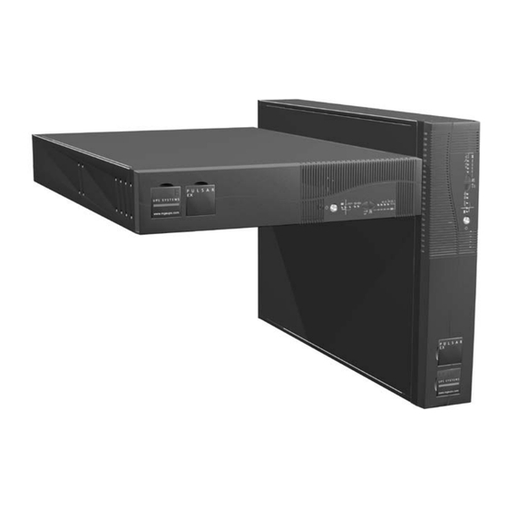
Page 7: Presentation
1. Presentation 1.1 System configurations Rack setup 17.25 inches (19" Rack mount) 18.75 inches (EX 700RT/EX 1000RT/EX 1500RT) 3.4 inches (2U) P U L S A R BYPASS 100% test www. mgeu ps.co Model Part Weight Number (Ibs/kg) Pulsar EX700RT 85070 42.0 lbs (19.0 kg) Tower setup... -
Page 8: Rear Panel
1. Presentation 1.2 Rear panel Slot for communication-card option. Pulsar EX700RT/EX1000RT RS232 communication port. USB communication port. Six NEMA 5-15/20R (EX 1500 RT), six NEMA-5-15R (EX 700 RT, EX 1000 RT) receptacles for connection to AC power load. Two programmable NEMA 5-15/20R (EX 1500 RT), two programmable NEMA-5-15R (EX 700 RT, EX 1000 RT) Pulsar EX1500RT... -
Page 9: Control Panel
1. Presentation 1.3 Control panel BYPASS test 100% ON / OFF. Operation on battery power. Operation in ON-LINE mode (backup power available). Alarms battery load Operation on bypass (no backup power available). remaining 100% 100% Status of programmable outlet 2: Supplied with power overload Status of programmable outlet 1:... -
Page 10: Installation
2. Installation 2.1 Unpacking RS232 communication cable. USB communication cable. Telescopic rails for mounting in 19" bay with mounting hardware. CD-ROM with the Solution-Pac and UPS Driver software. Product documentation. Two tower supports for the upright position. Page 10 - 86-153850-00 A01... -
Page 11: Installation In Rack Position
2. Installation 2.2 Installation in rack position Follow steps A to D for rack mounting of the UPS on the rails. The rails and the necessary mounting hardware are supplied in the box along with the UPS (see item 32 on page 10). A. -
Page 12: Installation In Tower Position
2. Installation 2.3 Installation in tower position Install the two tower supports for the upright position using provided hardware in the package. (see item 35 on page 10). Pull out the MGE Logo and model plates, then rotate them as shown. P U L S A R www .mge ups.c Page 12 -... -
Page 13: Connection To The Rs232 Or Usb Communication Port (Optional)
2. Installation 2.4 Connection to the RS232 or USB communication port (optional) 1. Connect the RS232 30 or USB 31 communication cable to the serial port or the USB port on the computer. 2. Connect the other end of the communica- tion cable 30 or 31 to the RS232 2 or USB 3 communication port on the UPS. -
Page 14: Connections
2. Installation 2.6 Connections CAUTION: Check that the indications on the rating plate (on the back of the UPS), correspond to your AC power system, and to the actual electrical consumption of all the equipment to be connected to the UPS. 1. -
Page 15: Operation
3. Operation 3.1 Start-up The protected equipment connected to the UPS can be energized, whether AC input power is available or not. CAUTION:The AC input power source must be present when energizing for the first time. 1. Press the ON / OFF button 16 . The buzzer beeps and all the LED's go ON. -
Page 16: Operation On Battery Power (Following Failure Of Ac Input Power)
3. Operation 3.3 Operation on battery power (following an AC input power failure) Transfer to battery power The AC power source is outside tolerances, LED 17 is ON, the buzzer beeps three times. BYPASS The AC power to equipment connected to the UPS is supplied by the battery. -
Page 17: Personalization (Optional)
3. Operation 3.4 Personalization (optional) Function Personalization parameters can be set and modified using the UPS Driver software installed on a computer that is connected to the UPS (see section 2.4 Connection to the RS232 communication port, page 13). NOTE: Check that the RS232 cable 30 is properly connected. UPS Driver installation: 1. -
Page 18: Output" Tab
3. Operation "Output" tab Personalization function Default setting Options Rated UPS voltage 120 V 100 V - 127 V Frequency working mode Autoselect Converter Rated UPS frequency F = 60 Hz 50 Hz UPS tolerance for AC power F ± 5% F ±... -
Page 19: Ups Remote Power Off
3. Operation 3.6 UPS Remote Power Off (RPO) Pulsar EX RT's are equipped with a Remote Power Off function (RPO) that can cut power to all the devices connected to the UPS using a remote user-operated contact. The function is implemented by opening a contact connected to the two terminals of connector 12 on the back of the UPS. -
Page 20: Maintenance
4. Maintenance 4.1 Troubleshooting If any of LED's 25 , 26 or 27 flash, there is a operating anomaly or an alarm. NOTE: If a LED flashes, the bargraph data is no longer displayed. Indication Diagnostic Correction LED 27 flashes and UPS overload. Overload is too long or too high. Check the power drawn by the the buzzer beeps. - Page 21 4. Maintenance Indication Signification Correction LED 26 flashes and UPS has detected a fault. the buzzer sounds Depending on the UPS personalization parameters continuously. (see section 3.4, page 17). There are two possibilities: The equipment connected to the UPS continues to Call the after-sales support receive AC power, but it is directly from the department.
-
Page 22: Replacement Of The Battery Module
4. Maintenance 4.2 Replacement of the battery module CAUTION: Load will not be protected during this procedure! Batteries constitute a danger (electrical shock, burns). The short-circuit current may be very high. Precautions must be taken for all handling. Safety Rules: Remove all watches, rings, bracelets and any other metal objects that may come into contact with the battery module. - Page 23 4. Maintenance F - Remove the battery module and proceed with replacement. BYPA 100% test Reinstallation of the battery module To reinstall the battery module perform this procedure in reverse order e.g., “F”, “E”, “D”,”C”, “B”, “A”. To maintain an identical level of performance and safety, use a battery module with the same rating as the battery module being replaced.
-
Page 24: Environment
UPS recycling at the end of service life: MGE UPS SYSTEMS, INC. undertakes to recycle, by certified companies and in compliance with all applicable regula- tions, all UPS products recovered at the end of their service life (contact your MGE UPS SYSTEMS, INC. branch office). Packing: UPS packing materials must be recycled in compliance with all applicable regulations. -
Page 25: Appendices
RELAY BATTERY POWER DC/DC CHARGER SUPPLY PUSH PULL BATTERY Pulsar EX 700RT Pulsar EX 1500RT Pulsar EX 1000RT Pulsar EXB 1500RT Output power rating 36VDC - 14 Ah 700 VA / 490 W 1500 VA / 1050 W 1000 VA / 700 W... -
Page 26: Glossary
6. Appendices 6.2 Glossary Authorized input voltage range Upper and lower input voltage thresholds within which the UPS can transfer to for transfer to bypass if fault or bypass in the event of a UPS fault or overload. overload Automatic bypass Automatic switch controlled by the UPS, used to connect the equipment directly to the AC-power source in the event of a UPS failure or an overload. -
Page 27: Index
6. Appendices 6.3 Index Automatic bypass ............21 ON-LINE mode..............9 Automatic start ..............17 Overload ..............9-18-20 Bargraph................20 Part Numbers..............7 Battery Personalization ..............17 End of backup time..........16 Battery ..............17 Fault..............9-15 Bypass ..............18 Low-battery warning ..........17 On/Off conditions ............17 Recycling ..............24 Output..............18 Replacement ............22-23 Programmable outlets ..........8-9-15 Transfer to battery power ........16 Buttons ................8-9... - Page 28 UPS SYSTEMS, INC. T H E U N I N T E R R U P T I B L E P O W E R P R O V I D E R M G E 1660 Scenic Avenue For service call: Costa Mesa, CA 92626, USA 1 800 523-0142...
Need help?
Do you have a question about the Pulsar EX 700RT and is the answer not in the manual?
Questions and answers