Regulus CSE2 MIX F W8 1F Installation And Operation Manual
Hide thumbs
Also See for CSE2 MIX F W8 1F:
- Installation and operation manual (24 pages) ,
- Installation and operation manual (20 pages) ,
- Installation and operation manual (16 pages)

Related Manuals for Regulus CSE2 MIX F W8 1F


Summary of Contents for Regulus CSE2 MIX F W8 1F
- Page 1 Installation and Operation Manual CSE2 MIX F W8 1F PUMP STATION CSE2 MIX F W8 1F...
-
Page 2: Table Of Contents
CHECK VALVE ................3.4. FILTER WITH MAGNET ..............3.5. BALL VALVES ................PUMP STATION CONNECTION EXAMPLES ......... PUMP STATION INSTALLATION ............. TEMPERATURE SENSOR INSTALLATION ..........OPTIONAL ACCESSORIES ..............APPENDIX – ACTUATOR ADJUSTMENT ..........Regulus CSE2 MIX F W8 1F - www.regulus.eu │... -
Page 3: Introduction
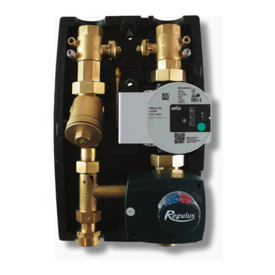
INTRODUCTION CSE2 MIX F W8 1F twin-line pump station is designed for mixed heating circuits. It provides flow through the heating system, mixes to the outlet temperature using a motorized mixing valve (controlled by an external controller). The pump station includes a filter with magnet, so it is also suitable for older steel pipe systems. -
Page 4: Pump Station Components
6 – Filter with magnet 7 – Lever for ball valves 8 – Ball valve w. sheath for temperature sensor (heating circuit return) 9 – Ball valve w. sheath for temperature sensor (heating circuit flow) Regulus CSE2 MIX F W8 1F - www.regulus.eu │... -
Page 5: Wilo-Para 25/8 Pump
2 - electric short circuit in pump 3 - pump overheated 1 - unforced fluid circulation through the pump flashing red and green 2 - pump speed lower than desired 3 - air in pump Regulus CSE2 MIX F W8 1F - www.regulus.eu │... - Page 6 To return to the factory settings, press and hold the operating button for at least 4 seconds (all LEDs flash for 1 second) and turn off the pump by unplugging. When switched on again, the pump will run at the factory settings. Regulus CSE2 MIX F W8 1F - www.regulus.eu │...
- Page 7 / n=const and the respective performance curve). LED indicators Operating mode Performance curve constant speed constant speed Δp-v variable Δp-v variable Δp-v variable Δp-c constant Δp-c constant Δp-c constant constant speed Regulus CSE2 MIX F W8 1F - www.regulus.eu │...
- Page 8 (e.g. pumps for HW storage tank heating) and for single- line heating systems with radiators. The pump maintains a constant set delivery head regardless of pumping capacity. Regulus CSE2 MIX F W8 1F - www.regulus.eu │...
- Page 9 Constant speed (n=const.) This profile is suitable for use in constant resistance systems that constant speed I, II, III require constant pumping capacity. The pump runs uncontrolled in three preset constant speed stages. Regulus CSE2 MIX F W8 1F - www.regulus.eu │...
-
Page 10: Mixing Valve W. Actuator
The ball valve can be accesses only after the front section of the insulation is removed. As a result, unintentional closure of the system by an unauthorized person is not possible. Regulus CSE2 MIX F W8 1F - www.regulus.eu │... - Page 11 OPEN CLOSED groove in the flow direction groove perpendicular to the flow direction Regulus CSE2 MIX F W8 1F - www.regulus.eu │...
-
Page 12: Pump Station Connection Examples
PUMP STATION CONNECTION EXAMPLES Regulus CSE2 MIX F W8 1F - www.regulus.eu │... - Page 13 Regulus CSE2 MIX F W8 1F - www.regulus.eu │...
-
Page 14: Pump Station Installation
Permissible and prohibited positions of the pump station Permissible positions Conditionally permissible positions Prohibited positions (may be used when a filter is replaced by the filter replacement section, code 19017) Regulus CSE2 MIX F W8 1F - www.regulus.eu │... -
Page 15: Temperature Sensor Installation
Temperature sensor placement Securing the temperature sensor with the screw Running the sensor cable through the recess in the insulation Regulus CSE2 MIX F W8 1F - www.regulus.eu │... - Page 16 Trimming the cable passage lock Installed sensors Regulus CSE2 MIX F W8 1F - www.regulus.eu │...
-
Page 17: Optional Accessories
A – Filter replacement section for CSE2 Code 19017 Loosen the union nut above and under Remove the filter and mount the filter the filter.. replacement section (code 19017) in its place. Regulus CSE2 MIX F W8 1F - www.regulus.eu │... - Page 18 Union 1“ Fu/M incl. gasket Code 15695 Remove both the connecting fittings. Install the union 15695 in their place, then attach the ball valve w. drain valve (17415) to the union. Regulus CSE2 MIX F W8 1F - www.regulus.eu │...
- Page 19 (for flow line of CSE2 pump stations) Code 18797 Remove both the connecting fittings. Install the extended union with check valve (18653) to the return line. Install the extended union (18797) to the flow line. Regulus CSE2 MIX F W8 1F - www.regulus.eu │...
- Page 20 D – Union to connect CSE2 to 5/4” manifold - 1“x5/4“ Fu/F Code 17920 Remove both the connecting fittings. Replace them with the union 17920 intended for connection to a manifold. Regulus CSE2 MIX F W8 1F - www.regulus.eu │...
-
Page 21: Appendix - Actuator Adjustment
Fit the plastic adapter on the shaft. The flat edge of the shaft and the arrow on the plastic adapter are located on the same side as the valve member. arrow on plastic adapter Regulus CSE2 MIX F W8 1F - www.regulus.eu │... - Page 22 The actuator shall be installed in the same manner as in the figure. v1.1-11/2021 ©2021 We reserve the right to errors, changes and improvements without prior notice. REGULUS spol. s r.o. E-mail: sales@regulus.eu Web: www.regulus.eu...
Need help?
Do you have a question about the CSE2 MIX F W8 1F and is the answer not in the manual?
Questions and answers