Regulus CSE2 MIX F G 1F Installation And Operation Manual
Pump station
Hide thumbs
Also See for CSE2 MIX F G 1F:
- Installation and operation manual (24 pages) ,
- Installation and operation manual (22 pages) ,
- Installation and operation manual (18 pages)

Related Manuals for Regulus CSE2 MIX F G 1F


Summary of Contents for Regulus CSE2 MIX F G 1F
- Page 1 Installation and Operation Manual CSE2 MIX F G 1F PUMP STATION CSE2 MIX F G 1F...
-
Page 2: Table Of Contents
AVC ACTUATOR FOR MIXING VALVE ......... 3.3. LK 840 MIXING VALVE ..............3.4. CHECK VALVE ................3.5. FILTER WITH MAGNET ..............3.6. BALL VALVES ................PUMP STATION INSTALLATION ............TEMPERATURE SENSOR INSTALLATION ..........OPTIONAL ACCESSORIES ..............Regulus CSE2 MIX F G 1F - www.regulus.eu │... -
Page 3: Introduction
4 x G 1“ F 17484 Code * A set of manifold connecting fittings can be purchased as optional accessories (see chapter 6) Data for CSE2 MIX F G 1F Pump Station Fluid working temperature 5 - 95 °C Max. working pressure... -
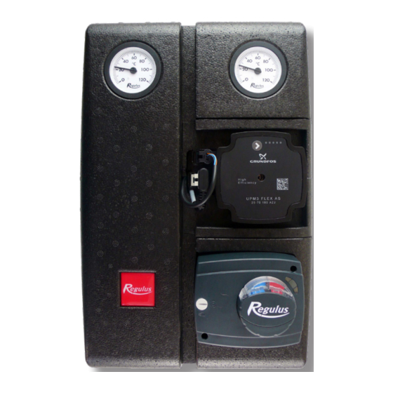
Page 4: Pump Station Components
6 – Dirt filter with magnet 7 – Lever for ball valves 8 – Ball valve w. sheath for temperature sensor (heating circuit outlet) 9 – Ball valve w. sheath for temperature sensor (heating circuit inlet) Regulus CSE2 MIX F G 1F - www.regulus.eu │... -
Page 5: Upm3 Flex As 25-75 130 Pump
PWM GND (blue) PWM out (black) PWM in (brown) socket for power supply (A) power supply (A) and and signal transmission (B) signal (B) connectors Pump Performance Curves Curve (upper graph) (lower graph) Regulus CSE2 MIX F G 1F - www.regulus.eu │... - Page 6 7,5 m ERROR DISPLAY The fault is indicated on the pump display by LEDS, as shown in the following figure. seized pump too low power supply voltage electric fault Regulus CSE2 MIX F G 1F - www.regulus.eu │...
-
Page 7: Avc Actuator For Mixing Valve
AVC ACTUATOR ELECTRICAL WIRING 1 – (blue) 2 – (black) 3– (brown) The actuator is factory-set and ready for operation. If it needs to be removed or replaced, follow the instructions in the appendix. Regulus CSE2 MIX F G 1F - www.regulus.eu │... -
Page 8: Lk 840 Mixing Valve
< 1 % Kv at 5m 5 mH O pressure difference Connections 3 x G 1“ M Materials Valve housing, spindle and member brass Gasket EPDM Mixing Valve Pressure Drop Diagram V [m³/h] Regulus CSE2 MIX F G 1F - www.regulus.eu │... -
Page 9: Check Valve
Dirt trapped on the magnet must be wiped off and then reassembled by inserting the strainer, screwing in and tightening the cap. Filter w. Magnet Pressure Drop Diagram V [m Regulus CSE2 MIX F G 1F - www.regulus.eu │... -
Page 10: Ball Valves
As a result, unintentional closure of the system by an unauthorized person is not possible. OPEN CLOSED groove in the flow direction groove perpendicular to the flow direction Regulus CSE2 MIX F G 1F - www.regulus.eu │... -
Page 11: Pump Station Installation
The package includes a mounting kit that is used to fix the pump station to the intended place. The mounting kit includes: Screw 5x50, round head 2 pcs 6.4 stainless steel washer, DIN 9021/A2 2 pcs Wall plug 8mm TX 2 pcs Regulus CSE2 MIX F G 1F - www.regulus.eu │... -
Page 12: Temperature Sensor Installation
Temperature sensor placement Securing the temperature sensor with the screw Running the sensor cable through the recess in the insulation Regulus CSE2 MIX F G 1F - www.regulus.eu │... -
Page 13: Optional Accessories
G 1“ Fu x G 1“ F x G 1/2“ M with manifold connection fittings Code 17928 – G 1“ Fu x G 5/4“ F manifold connection fittings Code 17920 code 17928 Regulus CSE2 MIX F G 1F - www.regulus.eu │... - Page 14 Fit the plastic adapter on the shaft. The flat edge of the shaft and the arrow on the plastic adapter are located on the same side as the valve arrow on member. plastic adapter Regulus CSE2 MIX F G 1F - www.regulus.eu │...
- Page 15 2 is closed). Having performed the check, tighten the fastening screw and switch back to automatic control. The actuator shall be installed in the same manner as in the figure. Regulus CSE2 MIX F G 1F - www.regulus.eu │...
- Page 16 ©2020 We reserve the right to errors, changes and improvements without prior notice. REGULUS spol. s r.o. E-mail: sales@regulus.eu Web: www.regulus.eu...
Need help?
Do you have a question about the CSE2 MIX F G 1F and is the answer not in the manual?
Questions and answers