Regulus CSE2 MIX-BP F W8 1F Installation And Operation Manual
Pump station
Hide thumbs
Also See for CSE2 MIX-BP F W8 1F:
- Installation and operation manual (20 pages) ,
- Installation and operation manual (12 pages) ,
- Installation and operation manual (20 pages)

Related Manuals for Regulus CSE2 MIX-BP F W8 1F


Summary of Contents for Regulus CSE2 MIX-BP F W8 1F
- Page 1 Installation and Operation Manual CSE2 MIX-BP F W8 1F PUMP STATION CSE2 MIX-BP F W8 1F...
-
Page 2: Table Of Contents
3.3. CHECK VALVE ................3.4. FILTER WITH MAGNET ..............3.5. BALL VALVES ................EXAMPLES OF PUMP STATION CONNECTION ........12 PUMP STATION INSTALLATION ............. TEMPERATURE SENSOR INSTALLATION ..........OPTIONAL ACCESSORIES ..............Regulus CSE2 MIX-BP F W8 1F - www.regulus.eu │... -
Page 3: Introduction
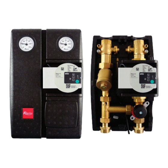
INTRODUCTION CSE2 MIX-BP F W8 1F twin-line pump station is designed for mixed heating circuits. It provides flow through the heating system, mixes to the outlet temperature by a manually controlled mixing valve (any actuator may be used that will meet the needs of the particular system and control). -
Page 4: Pump Station Components
7 – Ball valve w. sheath for temperature sensor (at return piping from heating circuit) 8 – Ball valve w. sheath for temperature sensor (at flow piping to heating circuit) 9 – mixing valve, no actuator Regulus CSE2 MIX-BP F W8 1F - www.regulus.eu │... -
Page 5: Wilo Para 25/8 Sc Pump
Energy Efficiency Index (EEI) ≤ 0.21 by EN 16297/3 IP rating IPX4D Motor protection integrated Pump Connection 1. POWER SUPPLY (1 ~ 230V, 50 Hz) brown (L) blue (N) yellow-green (PE) Regulus CSE2 MIX-BP F W8 1F - www.regulus.eu │... - Page 6 To return to the factory settings, press and hold the operating button for at least 4 seconds (all LEDs flash for 1 second) and turn off the pump by unplugging. When switched on again, the pump will run at the factory settings. Regulus CSE2 MIX-BP F W8 1F - www.regulus.eu │...
- Page 7 / n=const and the respective performance curve). LED indicators Operating mode Performance curve constant speed constant speed Δp-v variable Δp-v variable Δp-v variable Δp-c constant Δp-c constant Δp-c constant constant speed Regulus CSE2 MIX-BP F W8 1F - www.regulus.eu │...
- Page 8 HW storage tank heating) and for single- line heating systems with radiators. The pump maintains a constant set delivery head regardless of pumping capacity. Q [m³/ h] max. P [W] Q [m³/ h] Regulus CSE2 MIX-BP F W8 1F - www.regulus.eu │...
- Page 9 I, II, III constant speed constant resistance systems that require constant pumping capacity. The pump runs uncontrolled in three preset constant speed stages. Q [m³/ h] P [W] max. Q [m³/ h] Regulus CSE2 MIX-BP F W8 1F - www.regulus.eu │...
-
Page 10: Mixing Valve
The filter cap needs to be unscrewed, the metal strainer removed and rinsed thoroughly from any dirt. Dirt trapped on the magnet must be wiped off and then reassembled by inserting the strainer, screwing in and tightening the cap. Regulus CSE2 MIX-BP F W8 1F - www.regulus.eu │... -
Page 11: Ball Valves
As a result, unintentional closure of the system by an unauthorized person is not possible. OPEN CLOSED groove in the flow direction groove perpendicular to the flow direction Regulus CSE2 MIX-BP F W8 1F - www.regulus.eu │... -
Page 12: Examples Of Pump Station Connection
EXAMPLES OF PUMP STATION CONNECTION Regulus CSE2 MIX-BP F W8 1F - www.regulus.eu │... - Page 13 Regulus CSE2 MIX-BP F W8 1F - www.regulus.eu │...
-
Page 14: Pump Station Installation
Permitted and prohibited positions of the pump station Permitted positions Conditionally permissible positions Prohibited positions (may be used when a filter is replaced by the filter replacement section, code 19017) Regulus CSE2 MIX-BP F W8 1F - www.regulus.eu │... -
Page 15: Temperature Sensor Installation
Temperature sensor placement Securing the temperature sensor with the screw Running the sensor cable through the recess in the insulation Regulus CSE2 MIX-BP F W8 1F - www.regulus.eu │... - Page 16 Trimming the cable passage lock Installed sensors...
-
Page 17: Optional Accessories
A – Filter replacement section for CSE2 Code 19017 Loosen the unions above and under Remove the filter and mount the filter the filter. replacement section (code 19017) in its place. Regulus CSE2 MIX-BP F W8 1F - www.regulus.eu │... - Page 18 Union 1“ Fu/M incl. gasket Code 15695 Remove both the connecting fittings. Install the union 15695 in their place, then attach the ball valve w. drain valve (17415) to the union. Regulus CSE2 MIX-BP F W8 1F - www.regulus.eu │...
- Page 19 (for flow line of CSE2 pump stations) Code 18797 Remove both the connecting fittings. Install the extended union with check valve (18653) to the return line. Install the extended union (18797) to the flow line Regulus CSE2 MIX-BP F W8 1F - www.regulus.eu │...
- Page 20 Code 17920 Remove both the connecting fittings. Replace them with the union 17920 intended for connection to a manifold. v1.2-06/2022 ©2022 We reserve the right to errors, changes and improvements without prior notice. REGULUS spol. s r.o. E-mail: sales@regulus.eu Web: www.regulus.eu...
Need help?
Do you have a question about the CSE2 MIX-BP F W8 1F and is the answer not in the manual?
Questions and answers