Table of Contents
Advertisement
Quick Links
Advertisement
Table of Contents

Related Manuals for Riftek RF1010SL Series


Summary of Contents for Riftek RF1010SL Series
-
Page 2: Table Of Contents
3D Laser Measurement Machine, RF1010SL Contents Safety precautions ........................3 Electromagnetic compatibility ....................3 Laser safety..........................3 General information ........................4 Structure and operating principle....................4 Basic technical data ........................5 Dimensions ..........................6 Mounting and setup ........................6 Connection diagram ........................8 9.1. Signal block ........................8 9.1.1. Connection diagram....................8 9.1.2. -
Page 3: Safety Precautions
3D Laser Measurement Machine, RF1010SL Safety precautions • Use supply voltage and interfaces indicated in the machine specifications. • In connection/disconnection of cables, the machine power must be switched off. • Do not use machine in locations close to powerful light sources. •... -
Page 4: General Information
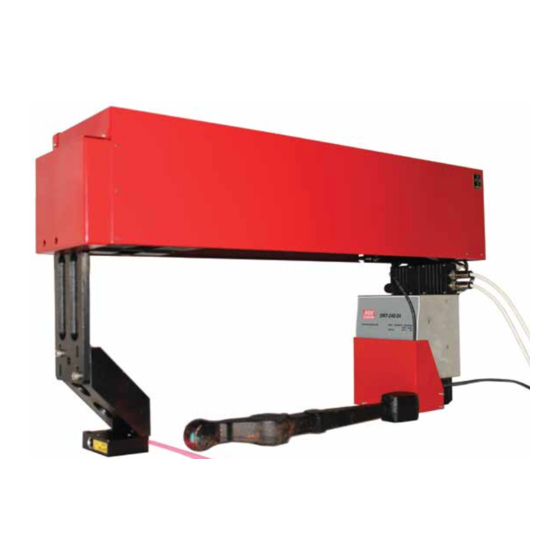
3D Laser Measurement Machine, RF1010SL General information The measuring machine is designed for non-contact measurement of geomet- rical parameters of objects, specifically suspension arms, and is a standalone software/ hardware system. Technical characteristics of the machine can be changed for a specific task. Structure and operating principle The work of the machine is based on the principle of 3D laser scanning of object/ objects with subsequent construction of a 3D computer model and determination of ge-... -
Page 5: Basic Technical Data
3D Laser Measurement Machine, RF1010SL Figure 2 The result is a 3D computer model of the object in the form of Point Cloud with established profile coordinates (X,Y,Z). An example of the model is shown in Figure 3. The required geometrical parameters are calculated from the resulting object model. Figure 3 Basic technical data Parameter... -
Page 6: Dimensions
3D Laser Measurement Machine, RF1010SL Measurement accuracy, X,Z axes, um ±50 Measurement accuracy, Y axis, um ±20 Sampling rate, profiles/s Speed, mm/s Parameters under control see point 10.1.2. 730х415х180 Dimension, mm Weight, kg alternating-current mains with sampling rate Power supply (50 ±... - Page 7 3D Laser Measurement Machine, RF1010SL Figure 5 Figure 6 At the measuring station mounting screws are loosened, providing horizontal motions of the support bracket, fig. 7,9. Figure 7 Figure 8...
-
Page 8: Connection Diagram
3D Laser Measurement Machine, RF1010SL Next is the station installation on the conveyer frame using M5 screws. After the station is installed it should be located at the distance from the conveyer according the installation dimensions, figure 4. Connection diagram Connection diagram is shown in Fig. -
Page 9: Led Indication
3D Laser Measurement Machine, RF1010SL Where 1 – stepper motor to laser scanner connection (cable entry); 2 - synchro- nization and machine condition digital outputs connection; 3 – power and limit switches connection (cable gland); 4 – network interface of the laser scanner connection (cable gland);... -
Page 10: Software
3D Laser Measurement Machine, RF1010SL 1 KOm 470 pF BAT54 BAT54 BZX84C3V3 Figure 13 The output stage of the machine condition output is shown in the Figure 14. The outputs are used to connect external alarm and actuators. 11 KOm BC847 5,1 KOm Figure 14... -
Page 11: Calculations
3D Laser Measurement Machine, RF1010SL Being started the application automatically searches for the devices of the measuring machine in the network and connects to them. If the devices aren’t connected to the network when the application is started, the process can be started forcedly by pressing the Connect button. - Page 12 3D Laser Measurement Machine, RF1010SL deviation of the central elbow axis position from the axis connecting centers of the two extreme elbows, mm. • Calculation of the axis displacement in the XZ-plane as maximum angle (in degrees) between the lines that run along the upper landing of the three elbows,.
-
Page 13: Input Tolerances And Setting Calculation Parameters
3D Laser Measurement Machine, RF1010SL The distances between the axes A, B and C in XY-plane are calculated. • Detail twisting calculation The maximum angle between the lines running along the upper landing of three elbows perpendicular to the detail axis is calculated, degrees. That is, the difference between the angles of these three lines is calculated pairwise. -
Page 14: Logging Events And Results
3D Laser Measurement Machine, RF1010SL Tabs Center distance and Twisting 10.1.4. Logging events and results During operation of the machine the scanning control application conducts event logging to the files system[index] in the /Log/ folder. The file title contains an index, when exceeding the current file size a new log file with the index for 1 bigger than the previous is created. -
Page 15: Detail Statistics Viewer
3D Laser Measurement Machine, RF1010SL In the main window of the application click Calibrate. After the block is scanned the machine is ready for operation. 10.2. Detail statistics viewer To view the statistics of measurements run RFStatViewer.exe. The main window of the application is shown in the Figure below. -
Page 16: Intended Use
3D Laser Measurement Machine, RF1010SL Condition Group enables to test the logic outputs, LEDs Group tests LED performance. To test the movement system set the number of steps and click Move. To return the carriage in the initial position click Ini Position. The other parameters are shown informative. -
Page 17: Operating The Machine
3D Laser Measurement Machine, RF1010SL 11.2. Operating the machine The geometric parameters measurement cycle is fully automated and operation of the machine is reduced to the work with the program. • run the machine control application • add/control the tolerances according to the Paragraph 10.1.3 •... -
Page 18: Routine Repairs
3D Laser Measurement Machine, RF1010SL 13. Routine repairs Possible troubles and trouble-shooting instructions are given in the following ta- ble. Troubles Possible cause Corrective actions Incorrect measure- The influence of an external illumination Remove the external source or protect ments source the controlled item from its influence.
Need help?
Do you have a question about the RF1010SL Series and is the answer not in the manual?
Questions and answers