
Related Manuals for Riftek RF656XY-35


Summary of Contents for Riftek RF656XY-35
- Page 1 SHAFTS GEOMETRY MEASUREMENT MACHINE RF800 Series User's manual 22, Logoisky tract, Minsk 220090, Republic of Belarus tel/fax: +375 17 281 36 57 info@riftek.com www.riftek.com Certified according to ISO 9001:2008...
-
Page 2: Table Of Contents
Shafts Geometry Measurement Machine. RF800 Series Contents Safety precautions .............................3 CE сompliance .............................3 Laser safety .............................3 General information .............................3 Structure and operating principle .............................3 5.1. Optical micrometer ............................3 5.1.1. Micrometer specifications ......................... 4 5.2. Structure ............................5 5.3. Operating principle ............................ -
Page 3: Safety Precautions
Shafts Geometry Measurement Machine. RF800 Series Safety precautions · All specialists must study this User's Manual before operating the machine. · Use supply voltage and interfaces indicated in the machine specifications. · In connection/disconnection of cables, the power must be switched off. ·... -
Page 4: Micrometer Specifications
Fig. 2. Figure 2 5.1.1. Micrometer specifications Optical micrometer, RF656XY-35 model Measurement range, mm ±6х35 Minimum size of the object, mm 0.25 Maximum size of the object, mm Accuracy, m ±1... -
Page 5: Structure
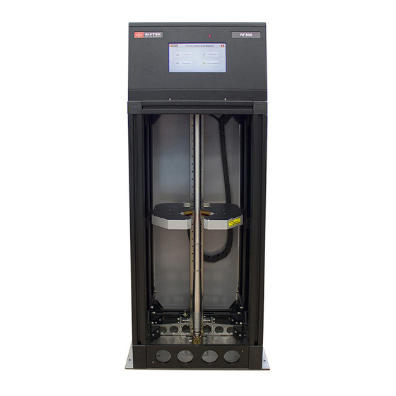
Shafts Geometry Measurement Machine. RF800 Series 5.2. Structure The structure of the machine (without protective doors) is illustrated in Figure 3. The machine contains a frame (1) on which a linear guide (2) of the linear translation system is installed. The linear guide has a carriage (3) driven by a stepper motor (4). An optical micrometer (5) is installed on the carriage (3). - Page 6 Shafts Geometry Measurement Machine. RF800 Series Figure 3 Figure 4 RF800 [Revision 1.0.0] 01.08.2018...
-
Page 7: Operating Principle
Shafts Geometry Measurement Machine. RF800 Series 5.3. Operating principle After the measurement algorithm has been programmed (position and number of controlled zones along the shaft, tolerances, etc. - see the software description), the operator installs a shaft into the machine. After a command from the operator (by the foot switch, or by the softkey on the touch screen), the linear translation system moves the micrometer along the shaft. -
Page 8: Software
Shafts Geometry Measurement Machine. RF800 Series Software 7.1. Main window After the machine is powered on, the software is loaded and the main window appears. Button Assignment Settings Set the measurement parameters. Calibration Perform the calibration procedure. Measurement Control the measurement process. Database View the database. -
Page 9: Language
Shafts Geometry Measurement Machine. RF800 Series The parameters menu is located in the left part of the window. The arrow in the upper left corner is used to go back to the previous window. 7.2.1. Language To select the language, tap Language. The following window appears: Select the language and tap Save. -
Page 10: Password
Shafts Geometry Measurement Machine. RF800 Series 7.2.2. Password To change the password, tap Password. The following window appears: Enter a new password and confirm it (the toggles in the fields are used to show/hide the entered characters). Tap Save. 7.2.3. Parameters To change parameters, tap Parameters. -
Page 11: Operator
Shafts Geometry Measurement Machine. RF800 Series Parameter Default Note value Calibration diameter D 20 mm The diameter of the caliber installed in the Morse taper (see p. 5.2.). Tolerance for 0.002 mm This tolerance is used when testing the calibration accuracy (see p. calibration 7.3.). -
Page 12: Adding / Editing The Part Template
Shafts Geometry Measurement Machine. RF800 Series In this window, you can see a list of controlled shafts with their unique numbers and names. Parameters of the selected shaft are shown in the table (the selected shaft is highlighted in blue in the list to the left). The description of parameters: Name Description... - Page 13 Shafts Geometry Measurement Machine. RF800 Series Enter the diameter value and the tolerance value into the Diameter field and the Tolerance field respectively. Enter the parameters of the controlled zone, namely, the position of the zone on the shaft (Size A) and the zone length (Size L). In addition, it is necessary to enter the number of controlled sections (Sections d): 2 or 3.
-
Page 14: Part Template Control
Shafts Geometry Measurement Machine. RF800 Series 7.2.5.2. Part template control To control the part template, tap This window displays the part template with the controlled zones. The proportions of the zones correspond to their size. To go back to the template creation window, tap RF800 [Revision 1.0.0] 01.08.2018... -
Page 15: Saving The Part Template
Shafts Geometry Measurement Machine. RF800 Series 7.2.5.3. Saving the part template To save the part template, tap Save. The program returns to the list of controlled parts and displays the parameters of the saved template. 7.2.6. Workplace The machine can be installed on workplaces of various types (production line, quality control department). -
Page 16: Calibration
Shafts Geometry Measurement Machine. RF800 Series · Select (Select button), or add (Add button), and then select the workplace number. · Select the controlled diameter from the Diameter drop-down list. · Describe the workplace in the Description text box. 7.3. Calibration To perform the calibration of the machine, go to the main menu and tap Calibration. -
Page 17: Intended Use
Shafts Geometry Measurement Machine. RF800 Series The Deviation column shows the difference between the actual value and the measurement result. The calibration is successful if the deviation value doesn't exceed the tolerance (Tolerance for calibration, see par. 7.2.3.). If the calibration is not successful, the following window appears: Zones, in which the measurement result exceeds the tolerance, are shown in red. -
Page 18: Visual Inspection
Shafts Geometry Measurement Machine. RF800 Series 8.1.1. Visual inspection Before operating, it is needed to ensure of the serviceability of the machine: · check the cables and ground wires, · check the condition of output windows of the micrometer, and, if necessary, wipe them with a soft lint-free cloth. -
Page 19: Shafts Of Different Diameters
(the part of the Morse taper) is placed within the measurement zone of the micrometer. Follow the steps below: 1. Start RF701_Controller.exe, which is in the Riftek install \RF701_Controller directory on the desktop of the mini-PC. 2. In the Settings menu, select a port: COM4. - Page 20 Shafts Geometry Measurement Machine. RF800 Series 4. Tap the GoToEnd button in order to move the micrometer to the lowest position. 5. Install the rack 3 (see Figure 4 in Catalog RF800.00.000) at the highest position. 6. Install the shaft into the machine. ATTENTION: the shaft must be installed! 7.
-
Page 21: Template Selection
Shafts Geometry Measurement Machine. RF800 Series 8. If the setting is incorrect, tap the GoToEnd button in order to move the micrometer to the lowest position. 9. Screw the rack 1-2 turns. 10. Repeat steps 6-9 until the beam axis of the micrometer is on the axis of the caliber. -
Page 22: Measurement
Shafts Geometry Measurement Machine. RF800 Series 8.2.5. Measurement After you select the template, the program prompts to start the measurement process: If you need to save the result to the database, select the Save data option. Tap the Measurement button, or press the foot switch. If the result is acceptable, the program will display the following: For more information, tap D3: RF800 [Revision 1.0.0] 01.08.2018... - Page 23 Shafts Geometry Measurement Machine. RF800 Series The shaft is considered suitable if the diameters in all three controlled sections of the zone are in the same sorting group, and if the ovality and taper do not exceed the tolerance set for this sorting group. To measure the shaft again or to measure the new shaft, install the shaft into the machine and repeat the measurement procedure described in this paragraph.
- Page 24 Shafts Geometry Measurement Machine. RF800 Series An example of measuring the shaft during the Quality Control (diameter D1): The selected template: During the measurement process, the program displays the following. RF800 [Revision 1.0.0] 01.08.2018...
- Page 25 Shafts Geometry Measurement Machine. RF800 Series The measurement result (acceptable): The measurement result (defective): For more information, tap the D1...D4 buttons. RF800 [Revision 1.0.0] 01.08.2018...
-
Page 26: Working With The Database
Shafts Geometry Measurement Machine. RF800 Series 8.3. Working with the database The results will be saved to the database, if the Save data option is enabled (see par. 8.2.5.). To go to the database, tap the Database button in the main window. The program will display the database: In the right part of the window there is a list of measured shafts and their parameters. - Page 27 Shafts Geometry Measurement Machine. RF800 Series To export data to a file, tap the Export button, select the file type and path: If successful, you will see the following message: RF800 [Revision 1.0.0] 01.08.2018...
-
Page 28: Maintenance
Controlling the quality of the optical signal allows to assess the degree of contamination. Please follow the steps below: 1. Run the executable file RF65x_View_Cortex.exe, which you can find in the Riftek install\RF65x_View_Cortex directory on the desktop of the mini-PC. RF800 [Revision 1.0.0] 01.08.2018... - Page 29 Shafts Geometry Measurement Machine. RF800 Series 2. In the Settings menu, select COM > COM4. 3. In the Settings menu, select Net Address > 1 in order to connect to the X channel of the micrometer. RF800 [Revision 1.0.0] 01.08.2018...
- Page 30 Shafts Geometry Measurement Machine. RF800 Series 4. Tap Connect to establish connection with the micrometer. 5. Tap View Start to run the Optical signal view mode. Windows are considered clean if the amplitude of signal irregularity does not exceed 150 units (vertical scale). An example of the signal when the windows of the micrometer are clean: An example of the signal when the windows of the micrometer have contamination: RF800 [Revision 1.0.0] 01.08.2018...
-
Page 31: Annual Maintenance Work
Shafts Geometry Measurement Machine. RF800 Series 6. If necessary, clean the windows. ATTENTION: Cleaning is best done with a soft dry lint-free cloth. In order to remove fingerprints or grease, use the alcohol or alcohol-ether mixture. Do not use scratching cleaners or other aggressive media. 7. -
Page 32: Distributors
Shafts Geometry Measurement Machine. RF800 Series Distributors AUSTRIA AUSTRALIA BENELUX MBM Industry & Rail Tech Applied Measurement Altheris B.V. GmbH Australia Pty Ltd Vlietweg 17a 2266KA Leidschendam RAILWAY INSTRUMENTS ONLY RAILWAY INSTRUMENTS ONLY The Netherlands Tullnerbachstra e 36, Thornton Plaza, Unit 5, Tel: +31 70 3924421 A-3002 Purkersdorf, Austria 27 Thornton Crescent, Mitcham... - Page 33 Shafts Geometry Measurement Machine. RF800 Series GERMANY GERMANY GERMANY Disynet GmbH BIP-Industrietechnik GmbH Finger GmbH & Co. KG Breyeller Str. 2 RAILWAY INSTRUMENTS ONLY OPTICAL MICROMETERS ONLY 41379, Brueggen Am Elisabethhof 22, Sapelloh 172, Tel: +49 2157 8799-0 D-14772 Brandenburg 31606 Warmsen, Germany Fax: +49 2157 8799-22 D-41379 Brueggen, Germany...
- Page 34 Shafts Geometry Measurement Machine. RF800 Series PORTUGAL RUSSIA RUSSIA UltraSens Sensorika-M LLC Diesel-test-Komplekt LLC Qt. da Portela, Lt. 22.1, Ap. 152 Dmitrovskoye shosse 64-4 620030, Karjernaya St, 16 3030 - 502 Coimbra, Portugal 127474, Moscow, Russia Ekaterinburg, Russia Phone +351 239 796 277 Tel: +7 499 487 0363 Tel/fax: +7 343 2227565 Fax: +351 239 918 267...
- Page 35 Shafts Geometry Measurement Machine. RF800 Series USA, CANADA, MEXICO Acuity Products of Schmitt Industries, Inc. 2765 NW Nicolai Street Portland, OR, 97210, USA Tel: +1 503 227 7908 Fax: +1 503 223 1258 sales@acuitylaser.com www.acuitylaser.com RF800 [Revision 1.0.0] 01.08.2018...
Need help?
Do you have a question about the RF656XY-35 and is the answer not in the manual?
Questions and answers