
Related Manuals for Riftek RF580 Series


Summary of Contents for Riftek RF580 Series
- Page 1 THICKNESS MEASUREMENT SYSTEM RF580 Series User's manual Certified according to ISO 9001:2015...
-
Page 2: Table Of Contents
Thickness Measurement System. RF580 Series Contents Safety precautions .............................3 CE сompliance .............................3 Laser safety .............................3 General information .............................3 Structure and operating principle .............................3 5.1. Laser sensors ............................4 5.2. Contact encoders ............................4 5.3. Indication device ............................4 5.4. Analog output controller RF002.1-485-8I ............................ -
Page 3: Safety Precautions
Thickness Measurement System. RF580 Series Safety precautions · Use supply voltage and interfaces indicated in the system specifications. · In connection/disconnection of cables, the system power must be switched off. · Do not use the system in locations close to powerful light sources. -
Page 4: Laser Sensors
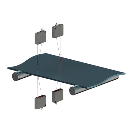
Thickness Measurement System. RF580 Series According to Scheme #2, the material thickness is defined as the difference in the distances to two surfaces of the material measured by each of the sensors. The position of the sensors is calibrated relative to each other. - Page 5 Thickness Measurement System. RF580 Series Figure 2. Overall and mounting dimensions of the indication device Designations: 1 - DB9 connectors for connecting the sensors (Point 1); 2 - DB9 connectors for connecting the sensors (Point 2); 3 - USB; 4 - Ethernet;...
-
Page 6: Analog Output Controller Rf002.1-485-8I
Thickness Measurement System. RF580 Series Basic technical data Parameter Value Thickness measurement range, mm by request Measurement error, mm ±0.1% of the laser sensors measurement range or according to the specification for encoders Input interface, sensors connection RS485 Output interface, result transfer... -
Page 7: Settings
Thickness Measurement System. RF580 Series Buttons assignment: Button Assignment Settings Open the "Settings" window. Measurement Open the "Thickness measurement" window. Calibration Calibrate the system. Database Browse the database. 8.1. Settings Before starting to work with the system, it is necessary to configure parameters. -
Page 8: Language
Thickness Measurement System. RF580 Series Select "Yes" to save the new password, or select "No" to cancel the action. 8.1.2. Language In order to change the language of the program, tap Language, select the language support file, and tap Select. -
Page 9: Parameters
Thickness Measurement System. RF580 Series In the Output signals section, the user can: · enable the Ethernet interface and specify the UDP port; · enable relay outputs and specify the pulse duration; · enable the analog output. In the Counter section, the user can enable the counter and specify the pulse step. -
Page 10: Sensors
Thickness Measurement System. RF580 Series Parameter Description Median Filter The median is formed from a preselected number of filtration points for measurement values. The incoming measured values are sorted again after each measurement. Subsequently, the mean value will be output as the median. -
Page 11: Measurement Scheme
Thickness Measurement System. RF580 Series 8.1.6. Measurement scheme The Scheme tab: In this tab, the user can create a measurement scheme with the required number of control points (points for measuring thickness or distance). One or two sensors can be used for measuring at each point. - Page 12 Thickness Measurement System. RF580 Series 3. For each point, select the sensors from the drop-down list. 4. Specify the nominal thickness value (Nominal value), tolerances (Tolerance '-' and Tolerance '+') and the value of the boundaries of the analog outputs.
-
Page 13: Operator
Thickness Measurement System. RF580 Series 8.1.7. Operator The Operator tab: In this tab, the user can enter the operator's data. Subsequently, when saving the measurement results to the database, the data of the selected operator is entered to the database. - Page 14 Thickness Measurement System. RF580 Series This window displays: · name of the selected set of parameters (to the right of the window name); · current measured thickness (green or red); · sensor readings (D1 and D2); · nominal thickness (Nominal);...
-
Page 15: Calibration
Thickness Measurement System. RF580 Series 8.3. Calibration The thickness of materials is controlled within the working range of a sensor (sensors). Figure 4.1. Scheme #1 Figure 4.2. Scheme #2 To get the optimum results of the thickness control, a sensor should be mounted so that the controlled surface (surfaces) of the sample of nominal thickness was located in the middle of the working range of a sensor. - Page 16 Thickness Measurement System. RF580 Series · Tap the Connect button to connect to the sensors. By default, the current measurement scheme is selected for calibration. In the Scheme drop-down list, you can select any other scheme. Calibration can be performed separately for each control point (in case there are more than one control point) or for all points simultaneously.
- Page 17 Thickness Measurement System. RF580 Series · Tap the Start button to start the measurement process. Parameters Value D1, Value D2, Thickness and Calibration point take values equal to the readings of the sensors in the sensor coordinate system. · Tap the Stop button.
-
Page 18: Operating The System
Thickness Measurement System. RF580 Series To work with the table, use a vertical scrollbar. To delete a single measurement, tap on it in the table and then tap the Delete button. To delete all measurements, select the All checkbox and then tap the Delete button. -
Page 19: Connecting Sensors To The Indication Device 9.2
Thickness Measurement System. RF580 Series 9.2. Connecting the analog output controller A separate power supply unit must be used for the analog output controller RF002.1-485-8I. Switching and power supply of sensors is also carried out through the controller. Figure 6. Connecting the analog output controller 1 –... -
Page 20: Encoder Input And Logical Output
Thickness Measurement System. RF580 Series An example of data packet for two control points: 55h,AAh,6Dh,5Dh,79h,02h,10h,00h,8Ah,C0h,08h,00h,ACh,C5h,08h,00h,00h,00h,00h,00h,00h,0 0h,00h,00h 55h, AAh - start of packet 02h, 44h - device number [580] 79h, 02h - packet number [cnt = 633] 10h, 00h - data size [16 bytes]... -
Page 21: Technical Support
Requests for technical assistance should be addressed at support@riftek.com, or by phone +375-17-3573657. Warranty policy Warranty assurance for the Thickness Measurement System RF580 Series - 24 months from the date of putting in operation; warranty shelf-life - 12 months. Revisions...
Need help?
Do you have a question about the RF580 Series and is the answer not in the manual?
Questions and answers