enphase IQ8AC Manual
Microinverters
Hide thumbs
Also See for IQ8AC:
- Installation and operation manual (35 pages) ,
- Installation and operation manual (37 pages) ,
- Installation and operation manual (41 pages)
Table of Contents
Advertisement
Quick Links
IN ST AL LAT I ON A ND OPE RAT ION MAN UA L
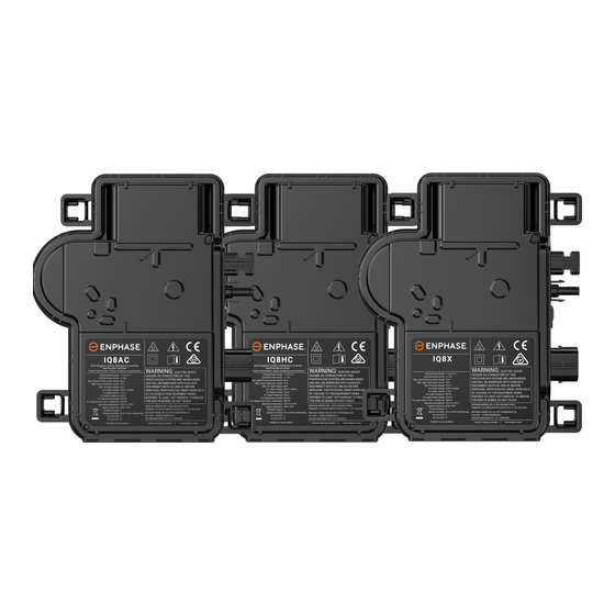
IQ8AC, IQ8HC, and IQ8X Microinverters
Applicable regions: ANZ
© 2024 Enphase Energy. All rights reserved. Enphase, the e and CC logos, and certain other marks listed at
https:/ /enphase.com/trademark-usage-guidelines
are trademarks of Enphase Energy, Inc. in the U.S. and other countries.
Data subject to change.
Advertisement
Table of Contents

Subscribe to Our Youtube Channel
Related Manuals for enphase IQ8AC


Summary of Contents for enphase IQ8AC
- Page 1 IQ8AC, IQ8HC, and IQ8X Microinverters Applicable regions: ANZ © 2024 Enphase Energy. All rights reserved. Enphase, the e and CC logos, and certain other marks listed at https:/ /enphase.com/trademark-usage-guidelines are trademarks of Enphase Energy, Inc. in the U.S. and other countries.
-
Page 2: Table Of Contents
Terminate the unused end of the IQ Cable..................20 Complete the installation of the junction box.................21 Connect the PV modules ........................22 4.10 Energize the system...........................22 4.11 Set up and activate monitoring......................23 Troubleshooting......................23 © 2024 Enphase Energy Inc. All rights reserved. September 2024 IOM-00107-1.0-EN... - Page 3 Bifacial modules..........................30 Anti-islanding............................30 PQ capability curve..........................30 Specifications........................ 30 IQ8AC-72-M-INT Microinverter specifications................31 IQ8HC-72-M-INT Microinverter specifications................33 IQ8X-80-M-INT Microinverter specifications................35 Enphase installation map ........................39 Enphase wiring diagram........................40 Revision history.......................42 © 2024 Enphase Energy Inc. All rights reserved. September 2024 IOM-00107-1.0-EN...
-
Page 4: Other Information
User documentation is updated frequently; check the Enphase website for the latest information https:/ /enphase.com/en-au/installers/resources/documentation. To ensure optimal reliability and to meet warranty requirements, the Enphase microinverter must be installed according to the instructions in this manual. For warranty text, see enphase.com/installers/ resources/warranty. -
Page 5: Important Safety Information
This manual contains important instructions for use during the installation and maintenance of the IQ8 Series Microinverters. IMPORTANT: Enphase IQ8 Series Microinverters listed in this manual require the IQ Cable. An IQ Gateway is required to monitor the performance and, where required, provides control of the IQ8 Series Microinverters. -
Page 6: Safety And Advisory Symbols
25 A. DANGER: Risk of electric shock. Do not use Enphase equipment in a manner not specified by the manufacturer. Doing so may cause death or injury to persons or damage to equipment. Be aware that installation of this equipment includes a risk of electric shock. -
Page 7: Microinverter Safety
90°C. To reduce the risk of burns, use caution when working with microinverters. DANGER: Risk of fire. The DC conductors of the PV module must be labelled PV Wire or PV Cable when paired with the Enphase microinverter. - Page 8 You must match the DC operating voltage range of the PV module with the allowable input voltage range of the Enphase microinverter. The Enphase microinverter is not protected from damage due to moisture trapped in cabling systems. Never mate microinverters to cables that have been left disconnected and exposed to wet conditions. This voids the Enphase warranty.
- Page 9 IQ Cable safety When installing the IQ Cable, secure any loose cable to avoid the risk of cable insulation abrasion against the roof surface. NOTE: When looping the IQ Cable, do not form loops smaller than 120 mm in diameter. Provide support for the IQ Cable every 300 mm. If you need to remove the IQ Sealing Cap, you must use the IQ Disconnect Tool.
-
Page 10: The Enphase Energy System
IQ8 Series Microinverters over on-site AC power lines and transmits the data to the Enphase App through a broadband or cellular connection. The IQ Gateway can monitor up to 300 IQ8 Series Microinverters. For details, refer to the Enphase IQ Gateway Installation and Operations Manual. -
Page 11: System Monitoring
60°C and much higher microinverter temperatures. 1.1.3 Ease of design PV systems using Enphase microinverters are very simple to design and install. You can install individual PV modules in any combination of PV module quantity, type, age, and orientation. Each microinverter quickly mounts on the PV racking directly beneath each PV module. -
Page 12: Compatibility
Refer to local electrical codes and standards for earthing requirements of PV array and racking. 2.3 Branch circuit capacity Plan your AC branch circuits to meet the following limits for the maximum number of microinverters per branch circuit. © 2024 Enphase Energy Inc. All rights reserved. September 2024 IOM-00107-1.0-EN... -
Page 13: Electricity Network Requirements
AC branch circuit to the circuit breaker in the electrical panel. Enphase recommends a voltage rise total of less than 2% from the start of IQ Cable to the point of supply. -
Page 14: Parts And Tools Required
IQ Gateway installation and operation manual at https:/ /enphase.com/en-au/installers/ resources/documentation. Enphase Installer App: Download the Enphase Installer App, open it, and log in to your • Enphase Account. Use it later to scan the microinverter serial numbers and connect to the IQ Gateway to track system installation progress. -
Page 15: Other Items
5. Manage the cabling 6. Connect the microinverters 7. Terminate the unused end of the IQ Cable 8. Complete the installation of the junction box 9. Connect the PV modules 10. Energize the system © 2024 Enphase Energy Inc. All rights reserved. September 2024 IOM-00107-1.0-EN... -
Page 16: Position The Iq Cable
50 mm for single-phase and 60 mm for three-phase. 4.2 Position the junction box 1. Verify that the AC voltage at the site is within range. © 2024 Enphase Energy Inc. All rights reserved. September 2024 IOM-00107-1.0-EN... -
Page 17: Mount The Microinverters
6 mm mounting hardware: 5 N m • 8 mm mounting hardware: 9 N m • When using mounting hardware from a third-party manufacturer, use the manufacturer's • recommended torque value. © 2024 Enphase Energy Inc. All rights reserved. September 2024 IOM-00107-1.0-EN... -
Page 18: Create An Installation Map
Figure 3: Horizontal mount Figure 4: Vertical Mount 4.4 Create an installation map The Enphase installation map is a diagram of the physical location of each microinverter in your PV array. Copy or use the Enphase installation map on page 39 to record microinverter placement for the system or provide your own layout if you require a larger or more intricate installation map. -
Page 19: Manage The Cabling
After creating the installation map, use the Enphase Installer App to record serial numbers and configure the system. For details, refer to Detect the Microinverters in the help topics of the Enphase Installer App. 1. Peel the removable serial number label from each microinverter and affix it to the respective location on the paper installation map. -
Page 20: Connect The Microinverters
IQ Sealing Caps are required for protection against moisture ingress. WARNING: Enphase microinverters cannot be installed without AC and DC connections and left overnight. All connections must be watertight from installation. -
Page 21: Complete The Installation Of The Junction Box
40 for more information. The following table lists the conductor colours. Single-phase Multi-phase Brown – L1 Brown – L1 Black – L2 Blue – N Grey – L3 Blue – N © 2024 Enphase Energy Inc. All rights reserved. September 2024 IOM-00107-1.0-EN... -
Page 22: Connect The Pv Modules
Full power production may take 20-30 minutes based on the number of microinverters in the system. 3. Check the LED on the connector side of the microinverter: © 2024 Enphase Energy Inc. All rights reserved. September 2024 IOM-00107-1.0-EN... -
Page 23: Set Up And Activate Monitoring
You can set the grid profile anytime through the Enphase Installer Platform, during system registration, or through the Enphase Installer App. You must have an IQ Gateway to set or change the grid profile. IQ Gateway installation and... -
Page 24: Troubleshooting
Follow all the safety measures described in this manual. Competent personnel can use the following troubleshooting steps if the PV system does not operate correctly. WARNING: Risk of electric shock. Do not attempt to repair the Enphase microinverter; it contains no user-serviceable parts. If it fails, contact Enphase Support at https:/ / enphase.com/contact/support... -
Page 25: Other Faults
WARNING: Risk of electric shock. Always de-energize the AC branch circuit before servicing. Never disconnect the DC or AC connectors under load. For the Enphase Energy Systems that include IQ System Controller 3 and IQ Battery 5P, turn the system shutdown switch to the OFF position. -
Page 26: Disconnect A Microinverter
If the connection is worn or damaged, it may need replacement. 14. Verify with your electricity network operator or with a multi-meter measuring frequency at the point of supply that the line frequency is within the range. If the problem persists, contact Enphase Support at https:/ /enphase.com/contact/support. -
Page 27: Install A Replacement Microinverter
LED on the connector side of the microinverter. 8. Use the Enphase Installer App to retrieve the old microinverter serial number from the IQ Gateway database. In the Enphase Installer App, once connected to the IQ Gateway: ©... -
Page 28: Enphase Iq Cable Planning And Ordering
9. Start the provisioning process for the newly added microinverter using the Enphase Installer App and by connecting the Enphase Installer App to IQ Gateway in AP mode. You can then Start Provisioning Devices through the Enphase Installer App. -
Page 29: Iq Cable Accessories
6. Technical data 6.1 Technical considerations Be sure to apply the following when installing the Enphase IQ8 Series Microinverters system: WARNING: Risk of equipment damage. You must match the DC operating voltage range of the PV module with the allowable input voltage range of the Enphase microinverter. -
Page 30: Bifacial Modules
PV module is at an open circuit (not operating). 6.2 Bifacial modules Enphase IQ8 Series Microinverters are compatible with bifacial PV modules if the temperature- adjusted electrical parameters (maximum power, voltage, and current) of the modules, considering the electrical parameters, including the bifacial gain, are within the allowable microinverter input parameters range. -
Page 31: Specifications
Minimum/Nominal/Maximum grid voltage 184/230/276 Rated/Maximum output current Arms 1.57/1.59 Nominal frequency Minimum/Maximum frequency 47/52 AC short-circuit fault current over three cycles Maximum AC output overcurrent protection device 20 (single-phase) and 25 (multi-phase) © 2024 Enphase Energy Inc. All rights reserved. September 2024 IOM-00107-1.0-EN... - Page 32 Torque specifications for fasteners (do not over- torque) 8 mm mounting hardware: 9 N m Cooling Natural convection - no fans Relative humidity range 4% to 100% (condensing) Approved for wet locations Altitude <2600 m © 2024 Enphase Energy Inc. All rights reserved. September 2024 IOM-00107-1.0-EN...
-
Page 33: Features And Specifications
Protective class (all ports) — 1 × 1 ungrounded array; no additional DC side PV array configuration protection required; AC side protection requires maximum 20 A (single-phase or multi-phase). © 2024 Enphase Energy Inc. All rights reserved. September 2024 IOM-00107-1.0-EN... - Page 34 Storage temperature range °C −40 to 85 Features and specifications 54-cell/108-half-cell, 60-cell/120-half-cell, 66-cell/132- Compatibility half-cell, 72-cell/144-half-cell Dimensions (without mounting brackets) 212 mm (8.3") × 175 mm (6.9") × 30.2 mm (1.2") © 2024 Enphase Energy Inc. All rights reserved. September 2024 IOM-00107-1.0-EN...
-
Page 35: Iq8X-80-M-Int Microinverter Specifications
Limits may vary. Refer to local requirements to define the number of microinverters per branch in your area. A minimum of two IQ8 Series Microinverters are required in the system. 7.3 IQ8X-80-M-INT Microinverter specifications DC parameters Parameter Unit Value Maximum input power © 2024 Enphase Energy Inc. All rights reserved. September 2024 IOM-00107-1.0-EN... - Page 36 Trip time accuracy (for trip times or delays <5 sec.) ±ms Trip time accuracy (for trip times or delays ≥5 sec.) Overvoltage class AC port/DC port — III/II Power factor setting — © 2024 Enphase Energy Inc. All rights reserved. September 2024 IOM-00107-1.0-EN...
-
Page 37: Miscellaneous Parameters
The DC circuit meets the requirements for ungrounded PV Earthing arrays. Ground fault protection (GFP) is integrated into the class II double-insulated microinverter. Enphase Installer Platform and Enphase App monitoring Monitoring options. Both options require an IQ Gateway. © 2024 Enphase Energy Inc. All rights reserved. September 2024 IOM-00107-1.0-EN... - Page 38 Limits may vary. Refer to local requirements to define the number of microinverters per branch in your area. A minimum of two IQ8 Series Microinverters are required in the system. © 2024 Enphase Energy Inc. All rights reserved. September 2024 IOM-00107-1.0-EN...
-
Page 39: Enphase Installation Map
Specifications 7.4 Enphase installation map © 2024 Enphase Energy Inc. All rights reserved. September 2024 IOM-00107-1.0-EN... -
Page 40: Enphase Wiring Diagram
Specifications 7.5 Enphase wiring diagram © 2024 Enphase Energy Inc. All rights reserved. September 2024 IOM-00107-1.0-EN... - Page 41 Specifications © 2024 Enphase Energy Inc. All rights reserved. September 2024 IOM-00107-1.0-EN...
-
Page 42: Revision History
Revision history 8. Revision history Revision Date Description IOM-00107-1.0 September 2024 Updated the IQ8 Series Microinverters cover image. Previous releases. © 2024 Enphase Energy Inc. All rights reserved. September 2024 IOM-00107-1.0-EN...
Need help?
Do you have a question about the IQ8AC and is the answer not in the manual?
Questions and answers