
Related Manuals for ProLights EclPar IPMFC


Summary of Contents for ProLights EclPar IPMFC
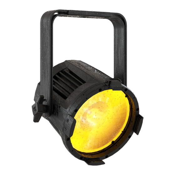
- Page 1 EclPar IPMFC 100W IP65 RGB+WW single source LED PAR USER MANUAL English version REV.01-08/23...
- Page 2 PROLIGHTS product are trademarks OWNED or licensed by Music & Lights S.r.l., its affiliates, and subsidiaries. PROLIGHTS is a registered trademark by Music & Lights S.r.l. All right reserved. Music & Lights – Via A. Olivetti, snc - 04026 - Minturno (LT) ITALY.
-
Page 3: Table Of Contents
LENS ASSEMBLY FROM INSIDE ..................40 16 - PERIODICAL CLEANING 17 - TEST OF IP65 RATING 18 - MAINTENANCE MAINTENANCE AND CLEANING THE PRODUCT............43 REPLACING THE FUSE ....................43 VISUAL CHECK OF PRODUCT HOUSING ..............43 TROUBLESHOOTING ..................... 44 PROLIGHTS - EclPar IPMFC... -
Page 4: Safety Information
• Do not reapply power until repairs have been completed. • Refer any service operation not described in this manual to PROLIGHTS Service team or an authorized PROLIGHTS service center. Installation •... - Page 5 • Warning! Disconnect the fixture from AC mains power and allow to cool for at least 10 minutes before handling. • Only technicians who are authorized by PROLIGHTS or Authorised service partners are permitted to open the fixture. • Users may carry out external cleaning, following the warnings and instructions pro- vided, but any service operation not described in this manual must be referred to a qualified service technician.
- Page 6 • This device complies with Part 15 of the FCC Rules. Operation is subject to the fol- lowing two conditions: 1. This device may not cause harmful interference, and 2. This device must accept any interference received, including interference that may cause undesired operation. Other approvals PROLIGHTS - EclPar IPMFC...
-
Page 7: Packaging
• RSR0630B: Cavo di sicurezza acciaio per corpi sospesi, moschettone inox, L=60 cm, nero • C6002B: Clamp in alluminio Slim, port.200Kg, tubi 48-51mm, perno M10, Black • 9533FCAL03: Cavo Ass. TH07 3x2.5mm, spina SCHUKO, presa MENAC3FCA, L.3 m PROLIGHTS - EclPar IPMFC... -
Page 8: Technical Drawing
2 - TECHNICAL DRAWING Ø169 mm [6.7 in] 263 mm 213 mm Ø457 mm [10.3 in] [8.4 in] [18.0 in] 13 mm 0,51 in 119 mm 4,68 in Fig. 01 Weight: 4,1Kg - 9,04 lbs PROLIGHTS - EclPar IPMFC... -
Page 9: Installation
Warning! When clamping the fixture to a truss or other structure at any angle, use clamps of half-cou- pler type. Do not use any type of clamp that does not completely encircle the structure when fastened. RSR0670A/B Steel security cable C6002 A/B clamp Fig.02 PROLIGHTS - EclPar IPMFC... -
Page 10: Connection To The Mains Supply
• Connect the power connector into the Mains input socket (100-240 VAC-50/60 Hz). • The product is then ready for its operations and can be controlled through the available input sig- nals on board. • To disconnect power from the product, disconnect the Mains from the socket. PROLIGHTS - EclPar IPMFC... -
Page 11: Product Overview
8. DMX OUT (5-p XLR): 1 = GND, 2 = sign-, 3 = sign+, 4 N/C, 5 N/C. 9. KNOB for bracket. 10. POWER OUT: power output for connection of multiple units in series. 11. ACCESSORY HOLDER for filter frame and barndoor accessory. Fig 03 PROLIGHTS - EclPar IPMFC... -
Page 12: Dmx Connection
... . DMX IN DMX OUT DMX IN DMX OUT DMX IN DMX OUT DMX IN DMX OUT DMX512 Controller Fig. 05 - Example 20 DMX channels configuration PROLIGHTS - EclPar IPMFC... -
Page 13: Construction Of The Dmx Termination
• The transmitter scans for all unlinked receivers for a period of about 5 seconds. • If the connection fails, check the position of the receiver. • The wireless icon on the receiver display indicates the received signal strength. PROLIGHTS - EclPar IPMFC... -
Page 14: In To Crmx
• The wireless icon on the receiver display indicates the received signal strength. CRMX TO DMX (RX) This function enable or disable the retransmission of the wireless DMX signal received throught the DMX port on the receiver side. PROLIGHTS - EclPar IPMFC... -
Page 15: Control Panel
• ENTER: used to confirm the current menu or confirm the current function value or option within a menu. • UP: browse upwards through the menu list and increases the numeric value dis- played. • DOWN: browse downwards through the menu list and decreases the numeric value displayed. PROLIGHTS - EclPar IPMFC... -
Page 16: Menu Structure
R,G,B Universe color: RGB code for an LED combo list that can easily be used to visually 2. Universe name by identify the universe by color. default takes first 16 characters of Model Name PROLIGHTS - EclPar IPMFC... - Page 17 HIGH LED MODE Set led operating mode. QUALITY HIGH BRIGHTNESS WHITE POINT 3200K Select CCT when RGBW@Full. 4000K 5600K 6000K 8000K PROLIGHTS - EclPar IPMFC...
- Page 18 MASTER DMX Allow you to link and operating in ALONE SLAVE synk multiple units without a DMX MASTER NO console. Choose a unit to perform as the Master. Master No DMX: fixture is SLAVE not broadcasting signal PROLIGHTS - EclPar IPMFC...
- Page 19 Check Color Macro Dimmer MACRO channel <000-255> Charts WHITE 2700K Dimmer PRESETS <000-255> 2800K G/M Point 3200K <-025-025> 3500K 4000K 4500K 5000K 5600K 6000K 6500K 7000K 8000K 9000K 10000K MANUAL <000-255> COLORS GREEN <000-255> BLUE <000-255> WHITE <000-255> PROLIGHTS - EclPar IPMFC...
-
Page 20: Shortcut
10 - SHORTCUT Keys Mode Description MENU + ENTER then Clear All Clear all value of functions + factory default power on UP + DOWN after Flip Display Directly flip display without enter inside menu power on PROLIGHTS - EclPar IPMFC... -
Page 21: Rdm Functions
DMX512 0x00E1 SCRIPTION Setup DMX512 DMX_START_ADDRESS 0x00F0 Setup DMX512 SLOT_INFO 0x0120 Setup DMX512 SLOT_DESCRIPTION 0x0121 Setup DMX512 DEFAULT_SLOT_VALUE 0x0122 Setup DMX512 DMX_BLOCK_ADDRESS 0x0140 Setup DMX512 DMX_FAIL_MODE 0x0141 Setup DMX512 DMX_STARTUP_MODE 0x0142 Setup Dimmer DIMMER_INFO 0x0340 Settings PROLIGHTS - EclPar IPMFC... - Page 22 LOCK_STATE_DESCRIPTION 0x0642 tion IDENTIFY_DEVICE Control 0x1000 RESET_DEVICE Control 0x1001 POWER_STATE Control 0x1010 PERFORM_SELFTEST Control 0x1020 SELF_TEST_DESCRIPTION Control 0x1021 CAPTURE_PRESET Control 0x1030 PRESET_PLAYBACK Control 0x1031 IDENTIFY_MODE Control 0x1040 PRESET_INFO Control 0x1041 PRESET_STATUS Control 0x1042 POWER_ON_SELF_TEST Control 0x1044 PROLIGHTS - EclPar IPMFC...
- Page 23 0-66 PIDs channel Manufacturer MANUAL RED 0x82C0 0-255 Linear Red 0% to 100% PIDs Linear Green 0% to Manufacturer MANUAL GREEN 0x82C1 0-255 PIDs 100% Linear Blue 0% to Manufacturer MANUAL BLUE 0x82C2 0-255 PIDs 100% PROLIGHTS - EclPar IPMFC...
- Page 24 1 - LED ERROR 2 - LED TEMPERATURE ERROR Manufacturer ERROR MESSAGES 0x82EA 3 - LED TEMP. SEN- PIDs SOR ERROR 4 - DRV ERROR 5 - CALIBRATION ERROR" Manufacturer CLEAN ALL DATA 0x82C8 0:NO,1:YES PIDs PROLIGHTS - EclPar IPMFC...
-
Page 25: Dmx Charts
CROSSFADE COLOR MA- BLUE GREEN BLUE FINE STROBE BLUE RED FINE WHITE CONTROL WHITE GREEN COLOR MA- WHITE FINE GREEN FINE STROBE BLUE CONTROL BLUE FINE WHITE WHITE FINE COLOR MA- CTO ON COLORS STROBE CONTROL PROLIGHTS - EclPar IPMFC... - Page 26 6000 6100 29127 30037 6100 6200 30037 30947 6200 6300 30947 31857 6300 6400 31857 32768 6400 6500 32768 33678 6500 6600 33678 34588 6600 6700 34588 35498 6700 6800 35498 36408 6800 6900 36408 37319 PROLIGHTS - EclPar IPMFC...
- Page 27 Default @ 128 Neutral Linear tint correction from -0.25 to +0.25 0 to 25% Crossfade from CCT to Color 8 bit value 16 bit value Function Note From From Linear Default @ 255 / 65535 Crossfade 65535 PROLIGHTS - EclPar IPMFC...
- Page 28 Pulse In from slow to fast Close Pulse Out from slow to fast Open Random from slow to fast Open Color Macro 8 bit value 16 bit value Function Note From From No Function Default @ 0 Green Blue Cyan Magenta PROLIGHTS - EclPar IPMFC...
- Page 29 Medium Blue-Green Peacock Blue Magenta Dark Pink Middle Rose Light Salmon English Rose Light Rose Orange Deep Amber Straw Light Amber Spring Yellow Dark Yellow Green Just Blue Sky Blue Lavender Light Lavender Pink Carnation Medium Pink PROLIGHTS - EclPar IPMFC...
- Page 30 Orange Deep Straw Rose Purple Deep Purple Soft Green Reserved for future 2700K 2800K 3000K 3200K 3400K 3600K 3800K 4000K 4200K 4400K 4600K 4800K 5000K 5200K 5400K 5600K 6000K 6500K 7000K 8000K 9000K 10000K FULL ON PROLIGHTS - EclPar IPMFC...
- Page 31 WHITE POINT 8000K LED FREQUENCY 600HZ LED FREQUENCY 1200HZ LED FREQUENCY 2000HZ LED FREQUENCY 4000HZ LED FREQUENCY 6000HZ LED FREQUENCY 25KHZ LED FREQUENCY 36KHZ LED FREQUENCY 40KHZ DMX FAULT HOLD DMX FAULT BLACKOUT DMX FAULT STAND ALONE PROLIGHTS - EclPar IPMFC...
- Page 32 STAND ALONE MASTER DMX STAND ALONE MASTER NO DMX STAND ALONE SLAVE STAND ALONE EFFECTS STAND ALONE FIXED COLORS STAND ALONE COLOR MACROS STAND ALONE WHITE PRESETS STAND ALONE MANUAL COLORS Reserved Reset all channel controlled Reserved PROLIGHTS - EclPar IPMFC...
-
Page 33: Error Messages
Communication failure between DISP and DRV Communication failure between calibra- [DRV ERROR] tion chip and DRV2 or Calibration returning unexpected/wrong datas [CALIBRATION ERROR] Blower for cooling the ignitor failed. IDENTIFICATION OF ELECTRONIC BOARDS Power Supply Master PCB Driver PCB Fig. 08 PROLIGHTS - EclPar IPMFC... -
Page 34: Accessories Installation
Open the Holder Clip and insert in the fixing lens accessory, pay attention to match the holders with the slots in the accessory. Mount the accessory for fixing lens on the lens cover and rotate to lock it. Fig.09 PROLIGHTS - EclPar IPMFC... -
Page 35: Epipmlens15
To distinguish the projection angle of different accessory lenses, they are identified by color: Fig.10 EPIPMLENS15 EPIPMLENS30 EPIPMLENS60 Code: Narrow Lens Medium Lens Lens Model: Wide Lens MAGENTA BLUE Color Code: 15° 30° Beam Angle: 60° PROLIGHTS - EclPar IPMFC... -
Page 36: Barn Door (Code Ajp7Zipbd - Optional)
BARN DOOR (CODE AJP7ZIPBD - OPTIONAL) DETAIL Lift the pin (1) upwards. Insert the filter frame (2) into the gel frame lock (DETAIL) and close down the snap. NOTE: To remove the accessory, reverse the procedure. Fig.11 PROLIGHTS - EclPar IPMFC... -
Page 37: Barn Door (Code Ajp7Zipbd - Optional)
BARN DOOR (CODE AJP7ZIPBD - OPTIONAL) DETAIL Lift the pin (1) upwards. Insert the barn door (2) into the gel frame lock (DETAIL) and close down the snap. NOTE: To remove the accessory, reverse the procedure. Fig.12 PROLIGHTS - EclPar IPMFC... -
Page 38: Full Snoot (Code Epipmfsnootbk - Optional)
FULL SNOOT (CODE EPIPMFSNOOTBK - OPTIONAL) DETAIL Lift the pin (1) upwards. Insert the snoot (2) into the gel frame lock (DETAIL) and close down the snap. NOTE: To remove the accessory, reverse the procedure. Fig.13 PROLIGHTS - EclPar IPMFC... -
Page 39: Honeycomb Louvre (Code Epipmhlouvrebk - Optional)
Open the Holder Clip and insert in the fixing lens accessory, pay attention to match the holders with the slots in the accessory. Mount the accessory for fixing lens on the lens cover and rotate to lock it. Fig.14 PROLIGHTS - EclPar IPMFC... -
Page 40: Concentric Louvre (Code Epipmclouvrebk - Optional)
Open the Holder Clip and insert in the fixing lens accessory, pay attention to match the holders with the slots in the accessory. Mount the accessory for fixing lens on the lens cover and rotate to lock it. Fig.15 PROLIGHTS - EclPar IPMFC... -
Page 41: Lens Assembly From Inside
Loosen the 8 M4x20 screws and the M4 washers to remove the lens cover and glass. Reflect cup Lens Mount the lens on the reflect cup and then carry out the reverse operation of the previous point to reassemble the lens cover with the glass. Fig.16 PROLIGHTS - EclPar IPMFC... -
Page 42: Lens Assembly From Inside
Unscrew the screws under the grommets and remove the cover with Figure 1. the connectors and the user interface as shown in Figure 2. Connect the radio board to the appropriate connector on the master pcb and secure the antenna using an nylon cable tie. Fig.17 PROLIGHTS - EclPar IPMFC... -
Page 43: Periodical Cleaning
16 - PERIODICAL CLEANING WARNING! Turn OFF power and allow approximately 20 minutes for the fixture to cool down. Use a soft cloth dampened with any detergent liquid for cleaning to remove the dirt from the optics. Fig. 18 PROLIGHTS - EclPar IPMFC... -
Page 44: Test Of Ip65 Rating
Insert the threaded end into the threaded valve Remove the gore valve from the side of fixture. hole socket. Connect the air hose to the IPTESTBOX by inserting the quick-connect fitting into the coupler. Fig. 19 PROLIGHTS - EclPar IPMFC... -
Page 45: Maintenance
WARNING: the use of alcohol or any other detergent could damage the lenses. • All other service operations on the product must be carried out by PROLIGHTS, its approved service agents or trained and qualified personnel. -
Page 46: Troubleshooting
• Check if the Fuse is intact and eventually replace it if fault necessary. • Contact the PROLIGHTS Service or authorized service partner. Do not remove parts and/or covers, or carry out any repairs or service that are not described in... - Page 48 PROLIGHTS is a trademark of prolights.it Via A.Olivetti snc MUSIC & LIGHTS S.r.l. support@prolights.it 04026 - Minturno (LT) ITALY musiclights.it Tel: +39 0771 72190...
Need help?
Do you have a question about the EclPar IPMFC and is the answer not in the manual?
Questions and answers