
Related Manuals for Samson 3296


Summary of Contents for Samson 3296
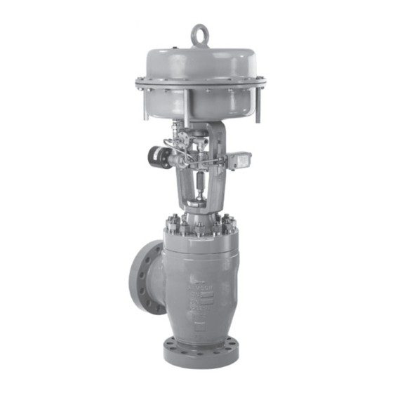
- Page 1 EB 8074 EN Translation of original instructions Type 3296 Valve · ANSI version In combination with an actuator, e.g. a Type 3271 or Type 3277 Pneumatic Actuator Edition May 2021...
- Page 2 Note on these mounting and operating instructions These mounting and operating instructions assist you in mounting and operating the device safely. The instructions are binding for handling SAMSON devices. The images shown in these instructions are for illustration purposes only. The actual product may vary.
-
Page 3: Table Of Contents
Contents Safety instructions and measures ..............1-1 Notes on possible severe personal injury ............1-5 Notes on possible personal injury ..............1-5 Notes on possible property damage .............1-8 Warnings on the device ................1-9 Markings on the device ................2-1 Valve nameplate ..................2-1 Actuator nameplate ..................2-2 Material identification number ..............2-2 Label when an adjustable packing is installed ..........2-2 Design and principle of operation ...............3-1... - Page 4 Removal ....................11-1 11.1 Removing the valve from the pipeline ............11-2 11.2 Removing the actuator from the valve ............11-2 Repairs ....................12-1 12.1 Returning devices to SAMSON ..............12-1 Disposal ....................13-1 Certificates ....................14-1 Annex......................15-1 15.1 Tightening torques, lubricants and tools ............15-1 15.2 Spare parts ....................15-1 15.3...
-
Page 5: Safety Instructions And Measures
SAMSON. SAMSON does not assume any liability for damage resulting from the failure to use the de- vice for its intended purpose or for damage caused by external forces or any other external factors. - Page 6 (see associated actuator documentation). When the valve is combined with a SAMSON Type 3271 or Type 3277 Pneumatic Actuator, the valve moves to a certain fail- safe position (see the 'Design and principle of operation' section) upon supply air or control signal failure.
- Page 7 Start-up and shutdown procedures fall within the scope of the operator's duties and, as such, are not part of these mounting and operating instructions. SAMSON is unable to make any statements about these procedures since the operative details (e.g. differential pressures and temperatures) vary in each individual case and are only known to the operator.
- Page 8 − Mounting and operating instructions for mounted valve accessories (positioner, solenoid valve etc.) − u AB 0100 for tools, tightening torques and lubricant − Manual u H 02: Appropriate Machinery Components for SAMSON Pneumatic Control Valves with a Declaration of Conformity of Final Machinery − For oxygen service: Manual u H 01...
-
Page 9: Notes On Possible Severe Personal Injury
Safety instructions and measures 1.1 Notes on possible severe personal injury DANGER Risk of bursting in pressure equipment. Valves and pipelines are pressure equipment. Impermissible pressure or improper opening can lead to valve components bursting. Î Observe the maximum permissible pressure for valve and plant. Î... - Page 10 Risk of personal injury due to preloaded springs. Valves in combination with pneumatic actuators with preloaded springs are under ten- sion. These control valves with SAMSON pneumatic actuators can be identified by the long bolts protruding from the bottom of the actuator.
- Page 11 Safety instructions and measures WARNING Risk of personal injury due to residual process medium in the valve. While working on the valve, residual medium can flow out of the valve and, depending on its properties, cause personal injury, e.g. (chemical) burns. Î...
-
Page 12: Notes On Possible Property Damage
Risk of valve damage due to the use of unsuitable tools. Certain tools are required to work on the valve. Î Only use tools approved by SAMSON (u AB 0100). Risk of valve damage due to the use of unsuitable lubricants. The lubricants to be used depend on the valve material. Unsuitable lubricants may cor- rode and damage surfaces. -
Page 13: Warnings On The Device
Safety instructions and measures 1.4 Warnings on the device Warning Meaning of the warning Location on the device Warning against moving parts There is a risk of injury to hands or fingers through the stroking movement of the actuator and plug stem if they are inserted into the yoke while the air supply is con- nected to the actuator. - Page 14 1-10 EB 8074 EN...
-
Page 15: Markings On The Device
2.1 Valve nameplate possible characteristics and options that may appear on a valve nameplate. Only the inscriptions relevant to the ordered Type 3296 Valve actually appear on the nameplate. Fig. 2-1: Inscriptions on the valve nameplate Item Inscription meaning Item Inscription meaning... -
Page 16: Actuator Nameplate
Markings on the device 2.4 Label when an adjustable The nameplate is affixed to the yoke of the valve (see Fig. 2-2). packing is installed An instructional label is affixed to the valve when an adjustable packing is installed (see Fig. 2-3). Fig. 2-3: Label when an adjustable packing is installed Fig. 2-2: Valve nameplate... -
Page 17: Design And Principle Of Operation
The process medium flows through the valve The Type 3296 Angle Valve with clamped in the direction indicated by the arrow on seat is preferably combined with a the body in the flow-to-open (FTO) direction. - Page 18 Design and principle of operation A26/27 Fig. 3-1: Type 3296 Valve with Type 3271 Pneumatic Actuator EB 8074 EN...
-
Page 19: Fail-Safe Positions
Depending on how the compression springs Actuators are arranged in the SAMSON Type 3271 and Type 3277 Pneumatic Actuator, the In these instructions, the preferable combina- valve has one of two different fail-safe posi- tion with a SAMSON Type 3271 or tions: Type 3277 Pneumatic Actuator is described. -
Page 20: Valve Accessories
(G ) at the top flange allow the Noise emissions sealing ability of the bellows to be moni- SAMSON is unable to make general state- tored. ments about noise emissions. The noise emis- Particularly for liquids and vapors, we rec-... - Page 21 Design and principle of operation Table 3-1: Technical data for Type 3296 Cast stainless steel Cast steel Cast steel Cast steel Material A352 LCC A216 WCC A217 WC6 A351 CF3M A351 CF8M Valve size NPS ½ to 8 Pressure rating Class 150 to 900...
- Page 22 Design and principle of operation Dimensions and weights Dimensions in mm and inches · Weights in kg and pounds Table 3-2: Dimensions for Type 3296 Valve ½ 1½ 3.62 3.62 4.37 5.88 6.94 8.88 10.69 Class 150 3.75 3.88 4.62 5.25 6.25 7.25...
- Page 23 Note Refer to the following data sheet for more dimensions and weights: u T 8074-1 The associated actuator documentation applies to actuators, e.g. SAMSON pneumatic actuators: u T 8310-1 for Type 3271 or Type 3277 Pneumatic Actuators up to 750 cm² actuator area u T 8310-2 for Type 3271 Actuator with 1000 cm² actuator area and larger u T 8310-3 for Type 3271 Actuator with 1400-60 cm²...
- Page 24 EB 8074 EN...
-
Page 25: Shipment And On-Site Transport
Shipment and on-site transport 4 Shipment and on-site trans- Î Leave the control valve in its transport container or on the pallet to transport it port on site. The work described in this section is only to Î Do not remove the protective caps from be performed by personnel appropriately the inlet and outlet until immediately be- qualified to carry out such tasks. - Page 26 NOTICE Risk of valve damage due to incorrectly attached slings. The lifting eyelet/eyebolt on SAMSON actu- ators is only intended for mounting and re- moving the actuator as well as lifting the ac- tuator without valve. Do not use this lashing point to lift the entire control valve assembly.
-
Page 27: Transporting The Valve
Shipment and on-site transport Fig. 4-1: Lifting points on the control valve: with flanges and additional lifting eyelet on the actuator (left) · With welding ends (right) 4.3.1 Transporting the valve − Protect the control valve against moisture and dirt. The control valve can be transported using −... - Page 28 Shipment and on-site transport Lifting instructions 3. Carefully lift the control valve. Check whether the lifting equipment and acces- − Use a hook with safety latch (see sories can bear the weight. Fig. 4-1) to secure the slings from slip- ping off the hook during lifting and 4.
-
Page 29: Storing The Valve
Elastomer, e.g. actuator diaphragm Î Avoid long storage times. − To keep elastomers in shape and to pre- Î Contact SAMSON in case of different vent cracking, do not bend them or hang storage conditions or longer storage them up. - Page 30 EB 8074 EN...
-
Page 31: Installation
–10 °C (14 °F) can perform all necessary work safely and Î Contact SAMSON if the mounting posi- easily access the device from the work posi- tion is not as specified above. tion. - Page 32 Installation Table 5-1: Inlet and outlet lengths Flow rate Inlet length Outlet length b x NPS State of process medium Valve conditions Inlet length a Outlet length b Inlet Outlet Ma ≤ 0.3 0.3 ≤ Ma ≤ 0.7 Ma ≤ 0.3 1) 0.3 ≤ Ma ≤ 0.7 1) Vapor Saturated steam (percentage of condensate > 5 %) Free of cavitation/w < 10 m/s Cavitation producing...
-
Page 33: Preparation For Installation
Installation Vent plugs NOTICE Vent plugs are screwed into the exhaust air Risk of control valve damage due to incor- ports of pneumatic and electropneumatic de- rect insulation. vices. They ensure that any exhaust air that Î Only insulate control valves with insulat- forms can be vented to the atmosphere (to ing section or bellows seal up to the bon- avoid excess pressure in the device). -
Page 34: Mounting The Device
Risk of valve damage due to the use of unsuitable tools. 1. Insert ball bearings (310) into the recess- Î Only use tools approved by SAMSON es in the bonnet. (u AB 0100). 2. Place the yoke (3) on the bonnet in such a way that the ball bearings fit into the recesses of the yoke. - Page 35 Installation (301) as far as they will go. Remove any on each side (see detailed view Y in excess material. Fig. 5-2). 7. Apply a thin film of lubricant (114) to the − The anti-rotation fixture does not get threads of the stem (9) and screws (303). stuck on the yoke and can move free- ly in the direction of travel.
- Page 36 Installation Plug stem Legend Yoke Screws Hanger Travel indicator scale Screws Castellated nut Warning label Ball bearing Fig. 5-1: Overview of yoke assembly with travel indicator scale in the standard version EB 8074 EN...
- Page 37 Installation Plug stem Legend Stem Lubricant Gleitmo 1763 V Clamps Screws Washers Sliding washers Fig. 5-2: Overview of anti-rotation fixture assembly in the standard version EB 8074 EN...
- Page 38 Installation b) Special version for Series 290 8. Thread the stem (9) upwards until the head of the stem rests on the extended Valves, NPS 2 to 4 actuator stem. See Fig. 5-3 and Fig. 5-4 9. Retract the actuator stem to relieve the stem (9).
- Page 39 Installation Legend Yoke Screws Plug stem Hanger Travel indicator scale Castellated nut Warning label Holder Screws Washers Fig. 5-3: Overview of yoke assembly with travel indicator scale in the special version EB 8074 EN...
- Page 40 Installation Plug stem Legend Stem Lubricant Gleitmo 1763 V Clamps Screws Washers Sliding washers Fig. 5-4: Overview of anti-rotation fixture assembly in the special version 5-10 EB 8074 EN...
- Page 41 Installation Table 5-3: Mounting dimensions for Types 3271 and 3277 Pneumatic Actuators · See Fig. 5-5 for dimensional drawing Trav- Actuator Actuator preloading Dimension when the valve is closed [mm] [cm²] [mm] [mm] NPS 2 to 4 · Special version 3.75 – – 22.5 118.5 67.5...
- Page 42 Installation Trav- Actuator Actuator preloading Dimension when the valve is closed [mm] [cm²] [mm] [mm] NPS 8 to 10 up to seat bore 200 · Standard version 1000 1400-60 87.5 1400-120 2800 5600 5-12 EB 8074 EN...
- Page 43 Installation Ball bearings (standard version only) Fig. 5-5: Dimensional drawing with mounting dimensions for Types 3271 and 3277 Pneumatic Actuators EB 8074 EN 5-13...
-
Page 44: Mounting The Actuator Onto The Valve
Installation 5.3.2 Mounting the actuator Depending on the version, SAMSON control valves are either delivered with the actuator onto the valve already mounted on the valve or the valve and actuator are delivered separately. When WARNING delivered separately, the valve and actuator Risk of personal injury due to preloaded must be assembled together on site. - Page 45 Installation Versions with perforated plug Only one hole is located near the seal facing of perforated plugs with equal percentage characteristic. Depending on the valve size, the hole pattern varies and is partly unsym- Plug metrical. The process medium in the valve stem flows through the holes as soon as the plug is lifted out of the seat.
-
Page 46: Installing The Valve Into The Pipeline
Installation 4. Fix the travel indicator scale into place 4. Lift the valve using suitable lifting equip- by tightening the screws. ment to the site of installation (see infor- mation under 'Lifting the valve' in the 5.3.3 Installing the valve into 'Shipment and on-site transport' section). -
Page 47: Testing The Installed Valve
Installation 5.4 Testing the installed valve cessories not fitted with noise-reducing fit- tings. Both can damage hearing. Î Wear hearing protection when working DANGER near the valve. Risk of bursting due to incorrect opening of pressurized equipment or components. Valves and pipelines are pressure equipment WARNING WARNING that may burst when handled incorrectly. -
Page 48: Leak Test
Installation 5. Check the valve for leakage to the atmo- WARNING sphere. Risk of personal injury due to preloaded 6. Depressurize the pipeline section and springs. valve. Actuators with preloaded springs are under 7. Rework any parts that leak (see informa- tension. -
Page 49: Travel Motion
Installation Î If the adjustable packing does not seal properly, contact our after-sales service. 5.4.2 Travel motion The movement of the actuator stem must be linear and smooth. Î Apply the maximum and minimum con- trol signals to check the end positions of the valve while observing the movement of the actuator stem. - Page 50 5-20 EB 8074 EN...
-
Page 51: Start-Up
Start-up 6 Start-up Î Wear hearing protection when working near the valve. The work described in this section is only to be performed by personnel appropriately qualified to carry out such tasks. WARNING WARNING Crush hazard arising from actuator and WARNING plug stem moving. - Page 52 Start-up Before start-up or putting the valve back into service, make sure the following conditions are met: − The valve is properly installed into the pipeline (see the 'Installation' section). − The leak and function tests have been completed successfully (see 'Testing the installed valve' in the 'Installation' sec- tion).
-
Page 53: Operation
Operation 7 Operation WARNING WARNING Immediately after completing start-up or put- Crush hazard arising from actuator and ting the valve back into operation, the valve plug stem moving. is ready for use. Î Do not insert hands or finger into the yoke while the air supply is connected to the actuator. -
Page 54: Manual Operation
Operation 7.2 Manual operation Valves with actuators fitted with a handwheel can be manually closed or opened in case of supply air failure. EB 8074 EN... -
Page 55: Malfunctions
Malfunctions 8 Malfunctions Read hazard statements, warnings and caution notes in the 'Safety instructions and mea- sures' section. 8.1 Troubleshooting Malfunction Possible reasons Recommended action Actuator and plug stem Actuator is blocked. Check attachment. does not move on Remove the blockage. demand. - Page 56 Malfunctions Malfunction Possible reasons Recommended action Increased flow through Dirt or other foreign Shut off the section of the pipeline and flush the closed valve (seat particles deposited valve. leakage) between the seat and plug. Valve trim is worn out. Replace seat and plug (see the 'Servicing' section) or contact our after-sales service.
-
Page 57: Emergency Action
Malfunctions 8.2 Emergency action Plant operators are responsible for emergen- cy action to be taken in the plant. In the event of a valve malfunction: 1. Close the shut-off valves upstream and downstream of the control valve to stop the process medium from flowing through the valve. - Page 58 EB 8074 EN...
-
Page 59: Servicing
Servicing 9 Servicing Î Allow components and pipelines to cool down or warm up to the ambient tem- The work described in this section is only to perature. be performed by personnel appropriately Î Wear protective clothing and safety qualified to carry out such tasks. gloves. - Page 60 Risk of valve damage due to the use of WARNING unsuitable tools. Risk of personal injury due to preloaded Î Only use tools approved by SAMSON springs. (u AB 0100). Actuators with preloaded springs are under tension. They can be identified by the long...
-
Page 61: Periodic Testing
Servicing 9.1 Periodic testing Note The control valve was checked by SAMSON Depending on the operating conditions, before it left the factory. check the valve at certain intervals to prevent − Certain test results certified by SAMSON possible failure before it can occur. Plant op-... - Page 62 Servicing Inspection and testing Action to be taken in the event of a negative result: Check the test connection and bellows Put the control valve out of operation (see the seal (if used) for external leakage. 'Decommissioning' section). To repair the bellows seal, WARNING! Risk of personal injury due contact our after-sales service (see the 'Repairs' section).
-
Page 63: Preparing The Valve For Service Work
Servicing 9.2 Preparing the valve for pressure must be removed and the air supply disconnected again and locked. service work WARNING Risk of personal injury due to incorrect re- We recommend removing the valve from the moval of the anti-rotation fixture under ten- pipeline before performing any service work sion. -
Page 64: Service Work
Servicing 9.4 Service work The following gaskets are installed and must be exchanged: Î Before performing any service work, − Gasket (17) preparations must be made to the control − Shim (125) valve (see section 9.2). − Seat retainer gasket (126) Î... - Page 65 Servicing Description Facing between the seat retainer gasket DF 1 (127) and body (1) Facing between the seat (4) and seat DF 2 retainer gasket (127) DF 10 Facing between the seat retainer (124) and DF 3 body (1) Facing between the shim (125) and seat DF 4 retainer gasket (127) Facing between the gasket (17) and shim...
- Page 66 Servicing NPS 6 and larger: place the gaskets (126) and shims (125) in alternating or- der into the groove of the seat retainer (124). Make sure the shims do not touch the facing (DF 6) of the body anywhere. 7. Insert the new gasket (17) into the groove of the seat retainer (124) and body (1).
- Page 67 14 Body nut 124 Seat retainer 15 Packing 125 Spacer ring 17 Body gasket 126 Seat retainer gasket 21 Insulating section 127 Seat bridge gasket Fig. 9-5: Type 3296 Valve: with standard bonnet (left) · With insulating section (right) EB 8074 EN...
-
Page 68: Replacing The Packing
Servicing 9.4.3 Replacing the packing 10. Apply a suitable lubricant to all the pack- ing parts and to the plug stem (5). 11. Slide the plug with plug stem (5) into the NOTICE bonnet (2). Risk of control valve damage due to incor- 12. - Page 69 Servicing Standard ADSEAL Form HT NPS ½ to 1½ NPS 2 to 4 15.1 15.2 Threaded bushing 15.2 Seal Spring Packing ring Washer Spacer Packing Spacer 15.1 Spacer ring with retaining ring Note The number of spacers (18, 19) varies depending on the nominal valve size. Fig. 9-6: Packing: standard (left) ·...
-
Page 70: Replacing The Seat And Plug
Servicing 18. Loosely screw the lock nut (10) and stem Insert the wire of the red spacer ring connector nut (9) onto the plug stem. (15.1) into the groove of the retaining ring. b) Form HT packing Slide the retaining ring over the plug stem. - Page 71 Servicing 14. Carefully place the new seat (4) in the Note body (1) and use the seat retainer (124) In versions with flow divider, it takes over the to clamp it into position. Align the seat function as a seat retainer (124), i.e. the seat retainer in such a way that an opening (4) is clamped in place by the flow divider faces toward the valve outlet.
- Page 72 Servicing A26/27 Fig. 9-7: Type 3296 Valve with Type 3271 Pneumatic Actuator 9-14 EB 8074 EN...
- Page 73 Servicing 1 Body 124 Seat retainer 2 Bonnet 125 Spacer ring 4 Seat 126 Seat retainer gasket 5 Plug (with plug stem) 127 Seat bridge gasket 8 Threaded bushing (packing nut) A4 Diaphragm 10 Lock nut A7 Actuator stem 14 Body nut A8 Ring nut 15 Packing A10 Spring...
-
Page 74: Determining The Number Of Gaskets Required
Servicing 9.4.5 Determining the number of gaskets required The following gaskets are installed and must be exchanged: − Gasket (17) − Shim (125) − Seat retainer gasket (126) Determining height H1 H1 is the height between the facing of the seat retainer (124) and the facing of the body (1). - Page 75 Servicing Determining height H2 H2 is the height of the new gasket(s) (126) at the seat retainer (124). See Fig. 9-9. 1. Measure H2 at three places evenly dis- tributed around the circumference. 2. Write down the measured values 1 to 3 in Table 9-2.
- Page 76 Servicing Selecting the shims is the height of the required shims. total 1. Calculate the height t based on the total previously determined values (see Table NPS ½ to 4 9-1 and Table 9-2) and enter it into Ta- ble 9-3. 2.
-
Page 77: Tightening The Body Nuts
Servicing 9.4.6 Tightening the body nuts NOTICE Risk of valve damage due to excessively high or low tightening torques. Observe the specified torques when tighten- ing control valve components. Excessive tightening torques lead to parts wearing out more quickly. Parts that are too loose may cause leakage. -
Page 78: Ordering Spare Parts And Operating Supplies
Servicing 9.5 Ordering spare parts and operating supplies Contact your nearest SAMSON subsidiary or SAMSON's After-sales Service for infor- mation on spare parts, lubricants and tools. Spare parts See Annex for details on spare parts. Lubricant See document u AB 0100 for details on suitable lubricants. -
Page 79: Decommissioning
Decommissioning 10 Decommissioning WARNING The work described in this section is only to Risk of personal injury due to pressurized be performed by personnel appropriately components and process medium being qualified to carry out such tasks. discharged. Î Do not loosen the screw of the test con- nection while the valve is pressurized. - Page 80 Decommissioning (e.g. due to seizing up after remaining in 2. Completely drain the pipelines and the same position for a long time), re- valve. lease any stored energy in the actuator 3. Disconnect and lock the pneumatic air (e.g. spring compression). See associat- supply to depressurize the actuator.
-
Page 81: Removal
Removal 11 Removal WARNING WARNING The work described in this section is only to Risk of personal injury due to residual be performed by personnel appropriately process medium in the valve. qualified to carry out such tasks. While working on the valve, residual me- dium can flow out of the valve and, depend- ing on its properties, cause personal injury, WARNING... -
Page 82: Removing The Valve From The Pipeline
Removal springs is transmitted to the actuator stem 3. Remove the valve from the pipeline (see and the stem (9). the 'Shipment and on-site transport' sec- Î First remove the actuator from the valve tion). or ensure it cannot transmit any forces to 11.2 Removing the actuator the actuator stem before removing the anti-rotation fixture on the plug stem. -
Page 83: Repairs
Î Do not perform any repair work on your side of your shipment so that the docu- own. ments are clearly visible. Î Contact SAMSON's After-sales Service 4. Send the shipment to the address given for repair work. on the RMA. - Page 84 12-2 EB 8074 EN...
-
Page 85: Disposal
Disposal 13 Disposal Î Observe local, national and internation- al refuse regulations. Î Do not dispose of components, lubricants and hazardous substances together with your household waste. EB 8074 EN 13-1... - Page 86 13-2 EB 8074 EN...
-
Page 87: Certificates
Pressure Equipment Directive 2014/68/EU on page 14-2 − Declaration of conformity in compliance with Machinery Directive 2006/42/EC for Types 3296-1 and 3296-7 Control Valves on page 14-3 − Declaration of incorporation in compli- ance with Machinery Directive 2006/42/EC for the Type 3296 Valve with other actuators other than Types 3271 and 3277 Actuators on... - Page 88 14-2 EB 8074 EN...
- Page 89 EB 8074 EN 14-3...
- Page 90 14-4 EB 8074 EN...
-
Page 91: Annex
Annex 15 Annex 15.1 Tightening torques, lubricants and tools u AB 0100 for tools, tightening torques and lubricants 15.2 Spare parts Shims (125) The shims are delivered as a set of seven Contact our after-sales service if you have shims with varying thickness (ranging from any questions concerning the suitability of 0.7 to 1.25 mm). - Page 92 Annex List of valve spare parts Body Gasket (bonnet) Bonnet Screw plug (test connection) Yoke Seal Seat Ring (pressure balancing) Plug (with plug stem) Gasket (pressure balancing) Gasket (pressure balancing) Guide bushing Support (pressure balancing) Threaded bushing (packing nut) Hex screw (pressure balancing) Stem connector nut Hex screw (pressure balancing) Lock nut...
- Page 93 Annex EB 8074 EN 15-3...
- Page 94 15-4 EB 8074 EN...
- Page 95 EB 8074 EN 15-5...
-
Page 96: After-Sales Service
You can reach our after-sales service at aftersalesservice@samsongroup.com. Addresses of SAMSON AG and its subsid- iaries The addresses of SAMSON AG, its subsid- iaries, representatives and service facilities worldwide can be found on our website (www.samsongroup.com) or in all SAMSON product catalogs. - Page 100 EB 8074 EN SAMSON AKTIENGESELLSCHAFT Weismüllerstraße 3 · 60314 Frankfurt am Main, Germany Phone: +49 69 4009-0 · Fax: +49 69 4009-1507 samson@samsongroup.com · www.samsongroup.com...
Need help?
Do you have a question about the 3296 and is the answer not in the manual?
Questions and answers