
Related Manuals for Samson 3281


Summary of Contents for Samson 3281
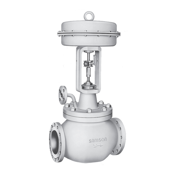
- Page 1 EB 8251 EN Translation of original instructions Type 3281 Steam Conditioning Valve · DIN version In combination with an actuator, e.g. a Type 3271 or Type 3277 Pneumatic Actuator Edition June 2021...
- Page 2 Note on these mounting and operating instructions These mounting and operating instructions assist you in mounting and operating the device safely. The instructions are binding for handling SAMSON devices. The images shown in these instructions are for illustration purposes only. The actual product may vary.
-
Page 3: Table Of Contents
Contents Safety instructions and measures ..............1-1 Notes on possible severe personal injury ............1-4 Notes on possible personal injury ..............1-5 Notes on possible property damage .............1-7 Markings on the device ................2-1 Valve nameplate ..................2-1 Actuator nameplate ..................2-2 Material identification number ..............2-2 Label when an adjustable packing is installed ..........2-2 Design and principle of operation ...............3-1 Fail-safe positions ..................3-1... - Page 4 Removal ....................11-1 11.1 Removing the valve from the pipeline ............11-2 11.2 Removing the actuator from the valve ............11-2 Repairs ....................12-1 12.1 Returning devices to SAMSON ..............12-1 Disposal ....................13-1 Certificates ....................14-1 Annex......................15-1 15.1 Tightening torques, lubricants and tools ............15-1 15.2 Spare parts ....................15-1 15.3...
-
Page 5: Safety Instructions And Measures
SAMSON. SAMSON does not assume any liability for damage resulting from the failure to use the de- vice for its intended purpose or for damage caused by external forces or any other external factors. - Page 6 (see associated actuator documentation). When the valve is combined with a SAMSON Type 3271 or Type 3277 Pneumatic Actuator, the valve moves to a certain fail- safe position (see the 'Design and principle of operation' section) upon supply air or control signal failure.
- Page 7 Start-up and shutdown procedures fall within the scope of the operator's duties and, as such, are not part of these mounting and operating instructions. SAMSON is unable to make any statements about these procedures since the operative details (e.g. differential pressures and temperatures) vary in each individual case and are only known to the operator.
-
Page 8: Notes On Possible Severe Personal Injury
− u AB 0100 for tools, tightening torques and lubricant − Manual u H 02: Appropriate Machinery Components for SAMSON Pneumatic Control Valves with a Declaration of Conformity of Final Machinery − When a substance is used in the device, which is listed as being a substance of very high... -
Page 9: Notes On Possible Personal Injury
Safety instructions and measures 1.2 Notes on possible personal injury WARNING Risk of burn injuries due to hot or cold components and pipelines. Depending on the process medium, valve components and pipelines may get very hot or cold and cause burn injuries. Î... - Page 10 Risk of personal injury due to preloaded springs. Valves in combination with pneumatic actuators with preloaded springs are under ten- sion. These control valves with SAMSON pneumatic actuators can be identified by the long bolts protruding from the bottom of the actuator.
-
Page 11: Notes On Possible Property Damage
Safety instructions and measures WARNING Risk of personal injury through incorrect operation, use or installation as a result of information on the valve being illegible. Over time, markings, labels and nameplates on the valve may become covered with dirt or become illegible in some other way. As a result, hazards may go unnoticed and the necessary instructions not followed. - Page 12 Risk of valve damage due to the use of unsuitable tools. Certain tools are required to work on the valve. Î Only use tools approved by SAMSON (u AB 0100). Risk of valve damage due to the use of unsuitable lubricants. The lubricants to be used depend on the valve material. Unsuitable lubricants may cor- rode and damage surfaces.
-
Page 13: Markings On The Device
Fig. 2-1 and the inscription table list all pos- 2.1 Valve nameplate sible characteristics and options that may appear on a valve nameplate. Only the in- scriptions relevant to the ordered Type 3281 Valve actually appear on the nameplate. Fig. 2-1: Inscriptions on the valve nameplate Item Inscription meaning... -
Page 14: Actuator Nameplate
Markings on the device The nameplate (80) is affixed to the yoke of the valve (see Fig. 2-2). Fig. 2-3: Label when an adjustable packing is installed Fig. 2-2: Location of the nameplate 2.2 Actuator nameplate See associated actuator documentation. 2.3 Material identification number The seat and plug of the valves have an item number written on them. -
Page 15: Design And Principle Of Operation
ST 3. The Type 3281 the inner wall of the flow divider. The steam Steam-conditioning Valve is preferably com- flow and the entrained water are mixed in bined with a SAMSON Type 3271 or... - Page 16 Plug (with plug stem) Castellated nut Guide bushing Diaphragm Threaded bushing (packing nut) Actuator stem Stem connector nut Ring nut Lock nut Spring Body nut A26/27 Stem connector clamps Packing Signal pressure connection Fig. 3-1: Type 3281 Valve with Type 3271 Pneumatic Actuator EB 8251 EN...
-
Page 17: Versions
We recommend installing a SAMSON In these instructions, the preferable combina- strainer upstream of the valve body and in tion with a SAMSON Type 3271 or the inlet pipe for the water supply. It prevents Type 3277 Pneumatic Actuator is described. solid particles in the process medium from The pneumatic actuator (with or without damaging the valve. -
Page 18: Valve Accessories
Design and principle of operation 3.4 Valve accessories not need to be shut down for service and re- pair work on the valve. Information Sheet u T 8350 Insulation Depending on the excessive heat that radi- Control valves can be insulated to reduce ates from the steam conditioning valve, only heat energy transfer. - Page 19 Design and principle of operation Noise emissions SAMSON is unable to make general state- ments about noise emissions. The noise emis- sions depend on the valve version, plant fa- cilities and process medium. Table 3-1: Technical data for Type 3281 Material Cast steel · 1.0619 Cast steel ·...
- Page 20 Dimensions and weights Table 3-2 and Table 3-3 provide an overview of the dimensions and weights of the standard version of Type 3281 Valve. The lengths and heights in the dimensional drawings are shown on p. 3-7. Dimensions in mm · Weights in kg Table 3-2: Dimensions of Type 3281 ·...
- Page 21 Refer to the following data sheets for more dimensions and weights: u T 8251 for valves with insulating section The associated actuator documentation applies to actuators, e.g. SAMSON pneumatic actu- ators: u T 8310-1 for Type 3271 or Type 3277 Pneumatic Actuators up to 750 cm² actuator area u T 8310-2 for Type 3271 Actuator with 1000 cm²...
- Page 22 EB 8251 EN...
-
Page 23: Shipment And On-Site Transport
2. Check the shipment for transportation Î Stay clear of suspended or moving damage. Report any damage to loads. SAMSON and the forwarding agent Î Close off and secure the transport paths. (refer to delivery note). 3. Determine the weight and dimensions of... - Page 24 Risk of personal injury due to the control A swivel hoist can be screwed into valve tipping over. SAMSON actuators with a female thread on Î Observe the valve's center of gravity. the top diaphragm case in place of the Î...
-
Page 25: Transporting The Valve
Shipment and on-site transport Fig. 4-1: Lifting points on the control valve: with flanges (left) and with welding ends (right) 4.3.1 Transporting the valve − Protect the piping and any mounted valve accessories against damage. The control valve can be transported using −... -
Page 26: Lifting The Valve
Shipment and on-site transport 4.3.2 Lifting the valve a) Version with flanges To install a large valve into the pipeline, use 1. Attach one sling to each flange of the lifting equipment (e.g. crane or forklift) to lift body and to the rigging equipment (e.g. hook) of the crane or forklift (see Fig. 4-1). -
Page 27: Storing The Valve
Elastomer, e.g. actuator diaphragm Î Avoid long storage times. − To keep elastomers in shape and to pre- Î Contact SAMSON in case of different vent cracking, do not bend them or hang storage conditions or longer storage them up. - Page 28 EB 8251 EN...
-
Page 29: Installation
To ensure the control valve functions proper- ly, follow the installation instructions given below: Î To determine the required inlet and outlet lengths as well as how the pipeline is to be routed, contact SAMSON. Water Throttled and cooled steam Superheated... -
Page 30: Preparation For Installation
Installation Support or suspension Î During connection of valve accessories, make sure that they are easily accessible and can be operated safely from the Note work position. The plant engineering company is responsi- ble for selecting and implementing a suitable Vent plugs support or suspension of the installed control Vent plugs are screwed into the exhaust air... -
Page 31: Mounting The Device
Risk of valve damage due to the use of ing the pipelines in the plant. unsuitable tools. Î Only use tools approved by SAMSON Î Pickle and blow through the steam pipe. (u AB 0100). Î For steam applications, dry the pipelines. -
Page 32: Mounting The External Anti-Rotation Fixture
The valve must NOTICE be closed beforehand. Impaired functioning due to incorrectly For SAMSON Type 3271 and Type 3277 applied lubricant. Actuators with Type 3273 Hand-operated Î Do not apply any lubricant to the threads Actuator, observe the mounting and operat- of the clamps (301) or the plug stem. - Page 33 Installation on each side (see detailed view Y in Fig. 5-3). − The anti-rotation fixture does not get stuck on the yoke and can move free- ly in the direction of travel. 14. Extend the actuator stem again and mount the stem connector clamps. Plug stem Legend Yoke...
- Page 34 Installation Plug stem Legend Stem Lubricant Gleitmo 1763 V Clamps Screws Washers Sliding washers Fig. 5-3: Overview of anti-rotation fixture assembly in the standard version EB 8251 EN...
- Page 35 Installation b) Special version for Se- 8. Thread the stem (9) upwards until the head of the stem rests on the extended ries 280 Valves, DN 50 to actuator stem. 9. Retract the actuator stem to relieve the stem (9). See Fig. 5-4 and Fig. 5-5 10. Gradually tighten the screws (303) in a 1.
- Page 36 Installation Legend Yoke Screws Hanger Plug stem Travel indicator scale Castellated nut Warning label Holder Screws Washers Fig. 5-4: Overview of yoke assembly with travel indicator scale in the special version EB 8251 EN...
- Page 37 Installation Plug stem Legend Stem Lubricant Gleitmo 1763 V Clamps Screws Washers Sliding washers Fig. 5-5: Overview of anti-rotation fixture assembly in the special version EB 8251 EN...
- Page 38 Installation Table 5-3: Mounting dimensions for Types 3271 and 3277 Pneumatic Actuators · See Fig. 5-6 for dimensional drawing Trav- Actuator Actuator preloading Dimension when the valve is closed [mm] [cm²] [mm] [mm] DN 50 to 100/NPS 2 to 4 · Special version 3.75 – – 22.5 118.5 67.5 34.5 103.5 82.5 34.5 1000 1400-60 – – 1400-120 2800 DN 125 to 150/NPS 6 · Standard version 263.5...
- Page 39 Installation Trav- Actuator Actuator preloading Dimension when the valve is closed [mm] [cm²] [mm] [mm] DN 200 to 250/NPS 8 to 10 up to seat bore 200 · Standard version 1000 1400-60 87.5 1400-120 2800 5600 DN 250/NPS 10, seat bore 250 and DN 300 to 500/NPS 12 to 20 · Standard version 1000 1400-60 1400-120 = 115 1) = 86 2) 2800 5600 = 86 2) FA = Actuator stem extends (fail-close) FE = Actuator stem retracts (fail-open) EB 8251 EN 5-11...
- Page 40 Installation Ball bearings (standard version only) Fig. 5-6: Dimensional drawing with mounting dimensions for Types 3271 and 3277 Pneumatic Actuators 5-12 EB 8251 EN...
-
Page 41: Mounting The Actuator Onto The Valve
Installation 5.3.2 Mounting the actuator Depending on the version, SAMSON control valves are either delivered with the actuator onto the valve already mounted on the valve or the valve and actuator are delivered separately. When WARNING delivered separately, the valve and actuator Risk of personal injury due to preloaded must be assembled together on site. -
Page 42: Installing The Valve Into The Pipeline
Installation Versions with perforated plug seal facing and is uncovered first when the plug is lifted out of the seat. Only one hole is located near the seal facing of perforated plugs with equal percentage Î On mounting the actuator, make sure characteristic. Depending on the valve size, that the hole uncovered first faces toward the hole pattern varies and is partly unsym- the valve outlet. - Page 43 Installation selection of the welding procedure and the 8. Attach a support or suspension on the actual welding operations on the valve. This valve, if necessary. also applies to any required heat treatment b) Version with welding ends to be performed on the valve. Î...
-
Page 44: Testing The Installed Valve
Installation 5.4 Testing the installed valve cessories not fitted with noise-reducing fit- tings. Both can damage hearing. Î Wear hearing protection when working DANGER near the valve. Risk of bursting due to incorrect opening of pressurized equipment or components. Valves and pipelines are pressure equipment WARNING WARNING that may burst when handled incorrectly. -
Page 45: Leak Test
Installation 5. Check the valve for leakage to the atmo- WARNING sphere. Risk of personal injury due to preloaded 6. Depressurize the pipeline section and springs. valve. Actuators with preloaded springs are under 7. Rework any parts that leak (see informa- tension. -
Page 46: Fail-Safe Position
Installation Î Apply the maximum and minimum con- trol signals to check the end positions of the valve while observing the movement of the actuator stem. Î Check the travel reading at the travel in- dicator scale. 5.4.3 Fail-safe position Î... -
Page 47: Start-Up
Start-up 6 Start-up Î Wear hearing protection when working near the valve. The work described in this section is only to be performed by personnel appropriately qualified to carry out such tasks. WARNING WARNING Crush hazard arising from actuator and WARNING plug stem moving. - Page 48 Start-up Before start-up or putting the valve back into 5. Check the valve to ensure it functions service, make sure the following conditions properly. are met: − The valve is properly installed into the pipeline (see the 'Installation' section). − The leak and function tests have been completed successfully (see 'Testing the installed valve' in the 'Installation' sec- tion).
-
Page 49: Operation
Operation 7 Operation Î Wear hearing protection when working near the valve. Immediately after completing start-up or put- ting the valve back into operation, the valve is ready for use. WARNING WARNING Crush hazard arising from actuator and WARNING plug stem moving. Risk of burn injuries due to hot or cold Î... -
Page 50: Normal Operation
Operation 7.1 Normal operation The handwheel of valves with actuators fitted with a handwheel must be in the neutral po- sition during normal operation. 7.2 Manual operation Valves with actuators fitted with a handwheel can be manually closed or opened in case of supply air failure. -
Page 51: Malfunctions
Malfunctions 8 Malfunctions Read hazard statements, warnings and caution notes in the 'Safety instructions and mea- sures' section. 8.1 Troubleshooting Malfunction Possible reasons Recommended action Actuator and plug stem Actuator is blocked. Check attachment. does not move on Remove the blockage. demand. WARNING! A blocked actuator or plug stem (e.g. due to seizing up after remaining in the same position for a long time) can suddenly start to move uncontrollably. - Page 52 Malfunctions Malfunction Possible reasons Recommended action Increased flow through Dirt or other foreign Shut off the section of the pipeline and flush the closed valve (seat particles deposited valve. leakage) between the seat and plug. Valve trim is worn out. Replace seat and plug (see the 'Servicing' section) or contact our after-sales service.
-
Page 53: Emergency Action
Malfunctions 8.2 Emergency action Plant operators are responsible for emergen- cy action to be taken in the plant. In the event of a valve malfunction: 1. Close the shut-off valves upstream and downstream of the control valve to stop the process medium from flowing through the valve. - Page 54 EB 8251 EN...
-
Page 55: Servicing
Servicing 9 Servicing Î Allow components and pipelines to cool down or warm up to the ambient tem- The work described in this section is only to perature. be performed by personnel appropriately Î Wear protective clothing and safety qualified to carry out such tasks. gloves. - Page 56 Risk of valve damage due to the use of WARNING unsuitable tools. Risk of personal injury due to preloaded Î Only use tools approved by SAMSON springs. (u AB 0100). Actuators with preloaded springs are under tension. They can be identified by the long...
-
Page 57: Periodic Testing
Servicing 9.1 Periodic testing Note The control valve was checked by SAMSON Depending on the operating conditions, before it left the factory. check the valve at certain intervals to prevent − Certain test results certified by SAMSON possible failure before it can occur. Plant op-... - Page 58 Servicing Inspection and testing Action to be taken in the event of a negative result: Check the test connection and bellows Put the control valve out of operation (see the 'Decommis- seal (if used) for external leakage. sioning' section). To repair the bellows seal, contact our af- WARNING! Risk of personal injury due ter-sales service (see the 'Repairs' section).
-
Page 59: Preparing The Valve For Service Work
Servicing 9.2 Preparing the valve for Note service work To remove an actuator with "stem extends" fail-safe action and/or with preloaded springs, a certain signal pressure must be WARNING applied to the actuator (see associated actu- Risk of personal injury due to incorrect re- ator documentation). -
Page 60: Service Work
Servicing 9.4 Service work Note Î Before performing any service work, Measure how many shims (64, 65) are re- preparations must be made to the control quired (see section 9.4.4). valve (see section 9.2). 1. Undo the body nuts (14) gradually in a Î... - Page 61 Plug (with plug stem) Castellated nut Guide bushing Diaphragm Threaded bushing (packing nut) Actuator stem Stem connector nut Ring nut Lock nut Spring Body nut A26/27 Stem connector clamps Packing Signal pressure connection Fig. 9-1: Type 3281 with Type 3271 Actuator EB 8251 EN...
-
Page 62: Replacing The Packing
Servicing See relevant information under 'Mount- Note ing the actuator onto the valve' in the 'In- The number of spacers (19) varies depend- stallation' section. ing on the nominal valve size. 9. Press the plug (5) firmly into the seat (4), while fastening down the bonnet (2) with the body nuts (14). - Page 63 Servicing Bonnet 17 Body gasket 62 Flow divider 63 Clamping element 64 Spacer ring 65 Spacer ring 67 Graphite fiber packing Fig. 9-2: Gaskets 13. Place the bonnet (2) together with the See relevant information under 'Mount- plug stem and plug (5) onto the body. ing the actuator onto the valve' in the 'In- Version with V-port plug: place the bon- stallation' section.
- Page 64 Servicing 17. Place yoke (3) on the bonnet (2) and fas- 3. Remove the tool. ten using the castellated nut (92). 4. Proceed as described in ‘Standard and 18. Loosely screw the lock nut (10) and stem form H packings’, steps 16 to 18. connector nut (9) onto the plug stem.
-
Page 65: Replacing The Seat And Plug
Servicing 9.4.3 Replacing the seat and 5. Unscrew the stem connector nut (9) and lock nut (10) from the plug stem. plug 6. Unscrew the threaded bushing (8). 7. Pull the plug with plug stem (5) out of the NOTICE bonnet (2). -
Page 66: Determining The Number Of Shims Required
Servicing See relevant information under 'Mount- After inserting the new gasket (17) as de- ing the actuator onto the valve' in the 'In- scribed in section 9.4.1, proceed as follows: stallation' section. 1. Determine dimension A. 17. Press the plug (5) firmly into the seat (4), 2. - Page 67 Servicing Bonnet Dim. Explanation Body gasket Bottom of the graphite fiber packing (67) up to the Flow divider top of the gasket (17) Clamping element Top of the shim (64/65) up to the top of the gasket Spacer ring (17) Spacer ring Height of the double-layered graphite fiber packing Graphite fiber packing...
-
Page 68: Ordering Spare Parts And Operating Supplies
Servicing 9.5 Ordering spare parts and operating supplies Contact your nearest SAMSON subsidiary or SAMSON's After-sales Service for infor- mation on spare parts, lubricants and tools. Spare parts See Annex for details on spare parts. Lubricant See document u AB 0100 for details on suitable lubricants. -
Page 69: Decommissioning
Decommissioning 10 Decommissioning WARNING The work described in this section is only to Risk of personal injury due to pressurized be performed by personnel appropriately components and process medium being qualified to carry out such tasks. discharged. Î Do not loosen the screw of the test con- nection while the valve is pressurized. - Page 70 Decommissioning (e.g. due to seizing up after remaining in 2. Completely drain the pipelines and the same position for a long time), re- valve. lease any stored energy in the actuator 3. Disconnect and lock the pneumatic air (e.g. spring compression). See associat- supply to depressurize the actuator.
-
Page 71: Removal
Removal 11 Removal WARNING WARNING The work described in this section is only to Risk of personal injury due to residual be performed by personnel appropriately process medium in the valve. qualified to carry out such tasks. While working on the valve, residual me- dium can flow out of the valve and, depend- ing on its properties, cause personal injury, WARNING... -
Page 72: Removing The Valve From The Pipeline
Removal springs is transmitted to the actuator stem 3. Remove the valve from the pipeline (see and the stem (9). the 'Shipment and on-site transport' sec- Î First remove the actuator from the valve tion). or ensure it cannot transmit any forces to 11.2 Removing the actuator the actuator stem before removing the anti-rotation fixture on the plug stem. -
Page 73: Repairs
Î Do not perform any repair work on your side of your shipment so that the docu- own. ments are clearly visible. Î Contact SAMSON's After-sales Service 4. Send the shipment to the address given for repair work. on the RMA. - Page 74 12-2 EB 8251 EN...
-
Page 75: Disposal
Disposal 13 Disposal Î Observe local, national and internation- al refuse regulations. Î Do not dispose of components, lubricants and hazardous substances together with your household waste. EB 8251 EN 13-1... - Page 76 13-2 EB 8251 EN...
-
Page 77: Certificates
The certificates shown were up to date at the time of publishing. The latest certificates can be found on our website: u www.samsongroup.com > Products & Applications > Product selector > Valves > 3281 Other optional certificates are available on request. EB 8251 EN 14-1... - Page 78 14-2 EB 8251 EN...
-
Page 79: Annex
Annex 15 Annex 15.1 Tightening torques, lubricants and tools u AB 0100 for tools, tightening torques and lubricants 15.2 Spare parts Body Screw plug (test connection) Bonnet (with connecting pipe) Ring nut/ring Yoke Packing ring Seat Gasket Plug Support Screw Guide bushing Screw Threaded bushing Threaded pin... - Page 80 15-2 EB 8251 EN...
- Page 81 EB 8251 EN 15-3...
-
Page 82: After-Sales Service
E-mail address You can reach our after-sales service at aftersalesservice@samsongroup.com. Addresses of SAMSON AG and its subsid- iaries The addresses of SAMSON AG, its subsid- iaries, representatives and service facilities worldwide can be found on our website (www.samsongroup.com) or in all SAMSON product catalogs. Required specifications Please submit the following details: −... - Page 84 EB 8251 EN SAMSON AKTIENGESELLSCHAFT Weismüllerstraße 3 · 60314 Frankfurt am Main, Germany Phone: +49 69 4009-0 · Fax: +49 69 4009-1507 samson@samsongroup.com · www.samsongroup.com...
Need help?
Do you have a question about the 3281 and is the answer not in the manual?
Questions and answers