Table of Contents
Advertisement
Quick Links
© 2023 Falcon® Electric, Inc. All rights reserved. Falcon® and the Falcon Electric logo are registered trademarks of Falcon Electric, Inc.
All other brand names and trademarks are the property of their respective owners. The information and specifications stated in this document are
subject to change without notice. OM480051 Rev. E, 9-2023
Falcon Electric, Inc.
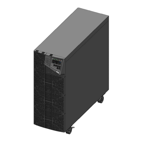
FN2 Series
Uninterruptible Power Supply
Installation & User Manual
Tower Models:
FN2-4.5K-2TXI
FN2-6K-2TXI
FN2-8K-2TXI
FN2-10K-2TXI
www.falconups.com
Advertisement
Table of Contents

Related Manuals for Falcon FN2-4.5K-2TXI


Summary of Contents for Falcon FN2-4.5K-2TXI
- Page 1 © 2023 Falcon® Electric, Inc. All rights reserved. Falcon® and the Falcon Electric logo are registered trademarks of Falcon Electric, Inc. All other brand names and trademarks are the property of their respective owners. The information and specifications stated in this document are subject to change without notice.
-
Page 3: Table Of Contents
Installation & User Manual Falcon Electric, Inc. Contents Safety ............................5 Retain This User Manual ......................5 Warnings ..........................5 Transportation ........................7 Storage ........................... 7 Operating Conditions ......................8 Introduction ..........................9 Overview ..........................9 UPS Features ......................... 9 UPS Block Diagram .......................10... - Page 4 Installation & User Manual Falcon Electric, Inc. N+1 / Parallel Operation ......................41 Constant Frequency Operation ....................42 Specifications ..........................43 Electrical ..........................43 Service & Warranty ........................44 Technical Support .........................44 Warranty ..........................45 FN2 Series OM480051 Rev.: E...
-
Page 5: Safety
Installation & User Manual Falcon Electric, Inc. Safety Retain This User Manual SAVE THESE INSTRUCTIONS: This manual contains important instructions which must be followed during the installation, operation, and maintenance of the FN2 Series UPS and batteries. Please read all instructions before operating this equipment and save this manual for future reference. - Page 6 Installation & User Manual Falcon Electric, Inc. CAUTION: A battery can present a risk of electrical shock and high short-circuit current. The following precautions should be observed when working on batteries: Remove watches, rings or other metal objects. • Use tools with insulated handles.
-
Page 7: Transportation
Installation & User Manual Falcon Electric, Inc. Symbols: Attention or consult accompanying documents. Input Output Alternating Current Direct Current Ground Recycle Do not dispose with ordinary trash. Transportation This UPS must be handled with care and given special attention due to the high amount of energy stored within its internal sealed, lead-acid batteries. -
Page 8: Operating Conditions
Installation & User Manual Falcon Electric, Inc. Operating Conditions The UPS must be installed in a clean, temperature controlled, indoor environment, free from moisture, flammable gasses, fumes, corrosive substances and conductive contaminants. Avoid direct sunlight. Do not install the UPS in a flammable or otherwise hazardous environment. -
Page 9: Introduction
The FN2 Series UPS continually regenerates new, AC power in pure sine wave for superior protection. This user manual provides basic information about the Falcon FN2 Series Uninterruptible Power Supply (UPS). FN2 models are available in nominal power ratings of 4500, 6000, 8000 and 10000 volt-amperes (VA). -
Page 10: Ups Block Diagram
Installation & User Manual Falcon Electric, Inc. UPS Block Diagram Transformer Pack Load Filter Filter Switch Galvanic NPC type Transformer External Option Charger a. Utility Input: AC source to the UPS. c. Utility Input Breaker: No-fuse Breaker (NFB) for UPS input over-current protection. -
Page 11: Product Overview
To file a claim for shipping damage or concealed damage: YOU MUST file with the carrier within 24 hours of receipt of the equipment; YOU MUST send a copy of the damage claim within 3 days to Falcon Electric, Inc. Box Contents The UPS system is shipped complete with all accessories required for operation. - Page 12 Installation & User Manual Falcon Electric, Inc. Accessories Kit: FN2 Series OM480051 Rev.: E...
-
Page 13: Front Panel
Installation & User Manual Falcon Electric, Inc. Front Panel Detail C 1. LCD Display 2. Green LED indicates N+1 operation is enabled. 3. Green LED indicates the utility input voltage is within the acceptable window. Flashing green LED indicates that the utility input voltage is outside the acceptable window. -
Page 14: Rear Panel
Installation & User Manual Falcon Electric, Inc. Rear Panel 4.5 to 6kVA Tower 8 to 10kVA Tower USB Port Terminal Resistor for parallel function CAN Bus Connection port for parallel function Communication Option Slot 1 (Channel A) Cooling Fan External Battery Connector... -
Page 15: Communication Port
The software bundled with the UPS is compatible with many operating systems such as Windows 2000, XP, Server 2003, VISTA, Server 2008, Windows 7 and Windows 10. For other applications such as Novell NetWare, Unix, or Linux, please contact Falcon. USB Port Complies with USB version 1.0,1.5 Mbps... -
Page 16: Lcd Display Icons
Installation & User Manual Falcon Electric, Inc. LCD Display Icons Icon Description Bypass input abnormal / UPS fails to transfer to bypass / Bypass abnormal at ECO mode Utility input abnormal Not Used Alarm Silent UPS Output overload Not Used... -
Page 17: Getting Started
Installation & User Manual Falcon Electric, Inc. Getting Started Installation This UPS must be installed in a clean environment, free from moisture, liquids, flammable gases or fumes and corrosive substances. Operate the UPS in an indoor environment within the temperature range of 0ºC to 40ºC (32ºF to 104ºF) To maximize battery life, a temperature range of 20ºC to 25ºC (68ºF to 77ºF) is ideal. -
Page 18: Ups Input Terminal Block
Installation & User Manual Falcon Electric, Inc. UPS Input Terminal Block Terminal 1 Input Configuration Table Terminal 1 Terminal 2 Terminal 3 Terminal 4 Utility Neutral Utility Line Jumper to Utility Ground (L2) (L1) FN2 Series OM480051 Rev.: E... -
Page 19: Ups Output Terminal Block
Installation & User Manual Falcon Electric, Inc. UPS Output Terminal Block 208V Output Terminal 1 208V Output Configuration Table (208V) Terminal 1 Terminal 2 Terminal 3 Terminal 4 Terminal 5 Terminal 6 120V 120V Ground Jumper N11 to L22... - Page 20 Installation & User Manual Falcon Electric, Inc. 208V / 120V Output Terminal 1 120V 208V Output Configuration Table (208V / 120V) Terminal 1 Terminal 2 Terminal 3 Terminal 4 Terminal 5 Terminal 6 Ground 120V 120V Jumper N11, L22 & G2...
- Page 21 Installation & User Manual Falcon Electric, Inc. Terminal 1 120V Output Configuration Table (120V) Terminal 1 Terminal 2 Terminal 3 Terminal 4 Terminal 5 Terminal 6 120V 120V Ground Jumper to Jumper to N11 Jumper to N22 Jumper to L11...
-
Page 22: Internal Ups Transformer Schematic
Installation & User Manual Falcon Electric, Inc. Internal UPS Transformer Schematic 120V 240V 208V Load 120V Internal UPS Transformer Configurations 120V 240V 120V 208V Load 208V 240V 120V 120V 120V 240V 208V Load 120V 120V 120V 240V 208V Load 120V 120V FN2 Series OM480051 Rev.: E... -
Page 23: Start-Up Procedure
Installation & User Manual Falcon Electric, Inc. Start-up Procedure AC Start 1. Verify input terminals are wired properly for 208V or 240V Utility Input Power. a. Verify all grounds are wired properly. 2. Turn on the input circuit breaker to start up the UPS. Green LEDs show that the Utility and Bypass inputs are normal. - Page 24 Installation & User Manual Falcon Electric, Inc. 5. The UPS is in self-test mode. The LCD display will change from figure C to figure D, and the UPS will remain in battery mode for approximately four seconds. Then the display will change from figure E1 to figure F if the self-test was successful.
-
Page 25: Battery Mode Start-Up (Cold Start)
Installation & User Manual Falcon Electric, Inc. Battery Mode Start-up (Cold Start) 1. Press the UPS On button once for approximately 5 seconds to turn on the UPS. The buzzer will sound twice. The LCD display will change from figure A to figure G for approximately 15 seconds. - Page 26 Installation & User Manual Falcon Electric, Inc. FN2 Series OM480051 Rev.: E...
- Page 27 Installation & User Manual Falcon Electric, Inc. FN2 Series OM480051 Rev.: E...
-
Page 28: Ups Settings And Functions
Installation & User Manual Falcon Electric, Inc. UPS Settings and Functions Settings: Verify that the UPS is operating normally. Then press the Function button to change the LCD display to figure Q1. 2. Press the Next Page button to scroll through the UPS settings. The LCD will display in sequence figure Q1 (buzzer) ... - Page 29 Installation & User Manual Falcon Electric, Inc. FN2 Series OM480051 Rev.: E...
- Page 30 Installation & User Manual Falcon Electric, Inc. 3. Press the Previous Page button to execute special functions. The functions include buzzer ON (as in figure Q1), buzzer OFF (as in figure Q2, Alarm silence for UPS Warning), and self-test OFF (as in figure R1) or self-test ON (as in figure R2). The UPS will execute the battery test for ten seconds.
- Page 31 Installation & User Manual Falcon Electric, Inc. d. Figures V1, V2, V3 and V4 indicate the operation modes of the UPS. Possible values are Std (Online), Eco (Economical) mode, Constant 50Hz Output and Constant 60Hz Output. e. Figure W indicates the fine tune range of inverter voltage which can be set from - 6V to +6V of rating voltage.
- Page 32 Installation & User Manual Falcon Electric, Inc. Bypass Mode 7. Verify the UPS is on and operating in Online Mode. a. Press the Off button for approximately 5 seconds, UPS will emit 2 beeps. b. UPS is in Bypass Mode i.
-
Page 33: Troubleshooting
Installation & User Manual Falcon Electric, Inc. Troubleshooting WARNING: Error Codes may require user to shut down and restart the UPS. MBS can be used to power the critical load while the UPS restart is taking place. Connected equipment may need to be turned off to prevent damage in case of a critical UPS failure. - Page 34 1. Verify Input / Output wiring. 2. Verify AC Input Source is within UPS acceptable voltage range. 3. If problems persist, reference the following table for possible conditions and solutions otherwise please contact Falcon Electric, Inc. Service Department. Error Code Description...
- Page 35 Disconnect and reconnect the RJ45 Er21 connector or set UPS with ID=1. Bypass voltage present in CF50 / CF60 Er24 constant mode. Please contact Falcon Electric, Inc. for resolution. Other error codes, contact Falcon Er** Service Department for further assistance.
-
Page 36: Batteries
The depleted batteries or packs may be returned to the Falcon Service Center at the end user’s expense for recycling. Prior to returning the depleted batteries or packs, please contact the Falcon Service Center and obtain a Return Material Authorization (RMA) number. -
Page 37: Battery Service Life (Float / Trickle Charge)
Installation & User Manual Falcon Electric, Inc. Battery Service Life (Float / Trickle Charge) The table below provides the typical battery service life during float / trickle charge. Ambient temperature greatly affects the overall battery life. Period Temperature Float Charge (Years) 25°... -
Page 38: Battery Replacement
Installation & User Manual Falcon Electric, Inc. Battery Replacement REFERENCE SAFETY SECTION OF THIS MANUAL FOR ALL BATTERY SAFETY WARNINGS. 4.5 to 6kVA Models 8 to 10kVA Models FN2 Series OM480051 Rev.: E... - Page 39 Installation & User Manual Falcon Electric, Inc. FN2 Series OM480051 Rev.: E...
-
Page 40: Options
Software: UPSilon Monitoring (Reference UPSilon manual for installation instructions.) 1. Connect supplied USB cable between UPS and PC workstation. Dry Contact Relay Card (Falcon Item #: UA88383) Pin 1: UPS on Bypass mode Pin 2: Utility Abnormal Pin 3: Utility Normal... -
Page 41: N+1 / Parallel Operation
Installation & User Manual Falcon Electric, Inc. N+1 / Parallel Operation Up to (4) FN2 Series UPSs may be connected in parallel to provide up to 24kVA capacity for 6kVA models and 40kVA capacity for 10kVA models. N+1 Parallel Redundant configuration allows up to 4 UPSs of the same capacity to be connected in parallel onto a common output bus. -
Page 42: Constant Frequency Operation
This option requires Bypass Line to be disabled internally. Please specify this option at • the time of order or contact Falcon Electric Service Department for details. • In constant frequency mode, the UPS output capacity is de-rated to 75% of its maximum capacity rating. -
Page 43: Specifications
Installation & User Manual Falcon Electric, Inc. Specifications Electrical *For latest released version, please visit our website at falconups.com. FN2 Series OM480051 Rev.: E... -
Page 44: Service & Warranty
Falcon with shipping damage. Falcon® Electric will not assume any responsibility for shipping damage. In the event shipping damage is found, you will be notified of the damage and be instructed to file a claim with the freight carrier. -
Page 45: Warranty
Falcon with an RMA number. For defective product sold domestically, as defined above, returned within 30 days of shipment, Falcon will pay for the shipping costs to and from its service center. For a defective product returned after 30 days but within 90 days of shipment, Falcon will only pay for shipping costs in sending the new or repaired product back to the end-user.
Need help?
Do you have a question about the FN2-4.5K-2TXI and is the answer not in the manual?
Questions and answers