
Related Manuals for Pickering 40-870


Summary of Contents for Pickering 40-870
- Page 1 40-870/2/3/4/5/6/7 User Manual PXI RF 50Ω Switching Modules pickeringtest.com Issue 6.7 April 2022...
- Page 2 © COPYRIGHT (2022) PICKERING INTERFACES. ALL RIGHTS RESERVED. No part of this publication may be reproduced, transmitted, transcribed, translated or stored in any form, or by any means without the written permission of Pickering Interfaces. Technical details contained within this publication are subject to change without notice.
- Page 3 Pickering Interfaces strives to fulfil all relevant environmental laws and regulations and reduce wastes and releases to the environment. Pickering Interfaces aims to design and operate products in a way that protects the environment and the health and safety of its employees, customers and the public. Pickering Interfaces endeavours to develop and manufacture products that can be produced, distributed, used and recycled, or disposed of, in a safe and environmentally friendly manner.
-
Page 4: Product Safety
If this product is heavy reference should be made to the safety instructions for provisions of lifting and moving. STATIC SENSITIVE To indicate that static sensitive devices are present and handling precautions should be followed. REED RELAY MODULE 40-110/115/120/125 RF 50Ω SWITCHING MODULES 40-870/872/873/874/875/876/877 Page (IV) Page (IV) -
Page 5: Table Of Contents
Pre Operation Checks ............3.1 Hardware Installation ............3.2 Software Installation .............3.2 Testing Operation ..............3.3 Section 4 Programming Guide ..............4.1 Programming Options For Pickering PXI Modules ....4.1 Programming RF Switches ...........4.2 Section 5 Connector Information ..............5.1 Section 6 Trouble Shooting .................6.1 Section 7 Maintenance Information ............7.1... - Page 6 THIS PAGE INTENTIONALLY BLANK RF 50Ω SWITCHING MODULES 40-870/872/873/874/875/876/877 Page (VI)
-
Page 7: Warnings And Cautions
Unused slots in the host chassis are populated with blanking plates to prevent access to user I/O signals that may be present. Blanking panels are available to order from Pickering in a variety of slot widths. If the product is not used in this manner for example by using an extender card then additional care must be taken to avoid contact with exposed signals. - Page 8 THIS PAGE INTENTIONALLY BLANK RF 50Ω SWITCHING MODULES 40-870/872/873/874/875/876/877 Page (VIII)
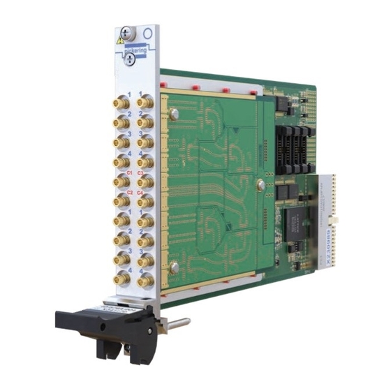
- Page 9 Supported by PXI or LXI Chassis y 3 Year Warranty The 40-870 is a 50 Ω RF Switch available with 3 or 6 separate SPDT relays in a single PXI slot. The module has low insertion loss and VSWR through the use of modern RF relay technology at an affordable cost.
- Page 10 (Plots taken from typical sample showing all connecting paths for parameter) 40-870 Typical VSWR Plot For Each Signal Path 40-870 Typical Insertion Loss Plot For Each Signal Path 40-870 Typical Crosstalk Plot Between Relay Inputs 40-870 Typical Crosstalk Plot Between Adjacent Teminals 40-870 Typical Isolation Plots For Each Input Channel pickeringtest.com...
- Page 11 Please contact your local sales office to discuss. Other Switching Specifications Mating Connectors & Cabling Maximum DC Voltage: 30 V Maximum DC Current: For connection accessories for the 40-870 range please refer to the 90-011D RF Cable Assemblies data sheet Operating Time: 3 ms typical...
- Page 12 The 40-872 is supplied with drivers that allow users to support the module in all popular PXI software environments. It can also be supported in all Pickering’s BANK 3 LXI Modular Switching chassis, allowing the use of a PXI or LAN controlled switching solution with the same high levels of performance.
- Page 13 40-872 Typical Insertion Loss Plot For Each Signal Path 40-872 Typical VSWR Plot For Each Signal Path 40-872 Typical Crosstalk Plot Between Signal Paths 40-872 Typical Crosstalk Plot Between MUX Banks 40-872 Typical Isolation Plots for each input channel pickeringtest.com RF 50Ω SWITCHING MODULES 40-870/872/873/874/875/876/877 Page 1.5...
- Page 14 Typically >36 dB to 3 GHz Product Customization Crosstalk: Typically <-42 dB to 1 GHz Pickering modules are designed and manufactured on our Typically <-35 dB to 3 GHz own flexible manufacturing lines, giving complete product Maximum RF Power: 10 W at 3 GHz control and enabling simple customization to meet very specific requirements.
- Page 15 PXI software attention to the mechanical and electrical design. environments. It can also be supported in all Pickering’s Versions with MCX or SMB connectors are available, LXI Modular Switching chassis, allowing the use of a PXI...
- Page 16 40-873 Typical Isolation Plot 40-873 Typical VSWR Plot - Terminated 40-873 Typical VSWR Plot - Signal Paths 40-873 Typical Crosstalk Plot - Channel to Channel 40-873 Typical Crosstalk Plot - Bank to Bank pickeringtest.com RF 50Ω SWITCHING MODULES 40-870/872/873/874/875/876/877 Page 1.8...
- Page 17 VSWR: Typically <1.2:1 to 1 GHz Product Customization Typically <1.3:1 to 3 GHz Pickering modules are designed and manufactured on our Termination VSWR: Typically <1.25:1 to 1 GHz own flexible manufacturing lines, giving complete product Typically <1.5:1 to 3 GHz...
- Page 18 The 40-874 is supplied with drivers that allow users to support the module in all popular PXI software environments. It can also be supported in all Pickering’s LXI Modular Switching chassis, allowing the use of a PXI or LAN controlled switching solution with the same high levels of performance.
- Page 19 40-874 Typical crosstalk between MUX banks (these measurements of crosstalk within each multiplexer for are measurements of crosstalk between the same paths neighbouring channels). through neighbouring multiplexers). 40-874 Typical Isolation Plots for each input channel. pickeringtest.com RF 50Ω SWITCHING MODULES 40-870/872/873/874/875/876/877 Page 1.11...
- Page 20 Note: VSWR measurements were carried out for each Product Customization selected input with the 50 Ω load fitted to the common Pickering PXI modules are designed and manufactured terminal of the multiplexer. on our own flexible manufacturing lines, giving complete Isolation: Typically >42 dB to 1 GHz...
- Page 21 The 40-875 is supplied with drivers that allow users to support the module in all popular PXI software environments. It can also be supported in all Pickering’s LXI Modular Switching chassis, allowing the use of a PXI or LAN controlled switching solution with the same high levels of performance.
- Page 22 40-875 Typical insertion loss plots for each channel. 40-875 Typical crosstalk between adjacent channels. 40-875 Typical crosstalk on adjacent channels between daughter cards (e.g. 1 & 9, 2 & 10 etc.) 40-875 Typical Isolation Plots for each input channel. pickeringtest.com RF 50Ω SWITCHING MODULES 40-870/872/873/874/875/876/877 Page 1.14...
- Page 23 Typically <1.3 dB to 3 GHz Product Customization VSWR: Typically <1.25 to 1 GHz Pickering PXI modules are designed and manufactured Typically <1.5 to 3 GHz on our own flexible manufacturing lines, giving complete Note: VSWR measurements were carried out for each product control and enabling simple customization to meet selected input with a 50 Ω...
- Page 24 The 40-876 is supplied with drivers that allow users BANK 3 to support the module in all popular PXI software environments. It can also be supported in all Pickering’s LXI Modular Switching chassis, allowing the use of a PXI or LAN controlled switching solution with the same high levels of performance.
- Page 25 40-876 Typical Insertion Loss Plot For Each Signal Path 40-876 Typical VSWR Plot For Each Signal Path 40-876 Typical Crosstalk Plot Between Signal Paths 40-876 Typical Crosstalk Plot Between MUX Banks 40-876 Typical Isolation Plots for each input channel pickeringtest.com RF 50Ω SWITCHING MODULES 40-870/872/873/874/875/876/877 Page 1.17...
- Page 26 Typically <1.5:1 to 3 GHz Product Customization Termination VSWR: Typically <1.25:1 to 1 GHz Pickering PXI modules are designed and manufactured Typically <1.5:1 to 3 GHz on our own flexible manufacturing lines, giving complete Isolation: Typically >50 dB to 1 GHz product control and enabling simple customization to meet Typically >44 dB to 2 GHz...
- Page 27 PXI software RF characteristics to 2.5 GHz with each path having a environments. It can also be supported in all Pickering’s nominally equal insertion loss. The 40-877 minimizes the LXI Modular Switching chassis, allowing the use of a PXI...
- Page 28 Module 2 Bank 2 Bank 2 2x2 Matrix 2x2 Matrix 2x2 Matrix Y Loop-Thru Two 40-877 Modules Interconnected as an 8x2 Matrix Y Loop-Thru Two 40-877 Modules Interconnected as a 4x4 Matrix pickeringtest.com RF 50Ω SWITCHING MODULES 40-870/872/873/874/875/876/877 Page 1.20...
- Page 29 40-877 Typical Insertion Loss Plot - Matrix Path 40-877 Typical Isolation Plot - Matrix Path 40-877 Typical Crosstalk Plot -Matrix Path 40-877 Typical VSWR Plot - Loop-thru 40-877 Typical VSWR Plot - Matrix Path pickeringtest.com RF 50Ω SWITCHING MODULES 40-870/872/873/874/875/876/877 Page 1.21...
- Page 30 VSWR: Typically <1.3:1 to 1 GHz Product Customization Typically <1.5:1 to 2.5 GHz Pickering PXI modules are designed and manufactured Isolation: Typically >55 dB to 1 GHz on our own flexible manufacturing lines, giving complete Typically >44 dB to 2 GHz product control and enabling simple customization to meet Typically >32 dB to 2.5 GHz...
-
Page 31: Specification Common To All Modules
We provide a full range of supporting cable and connector solutions for all our switching products—20 connector families with 1200+ products. We offer everything from simple mating connectors to complex cables assemblies and terminal blocks. All assemblies are manufactured by Pickering and are guaranteed to mechanically and electrically mate to our modules. Connectors & Backshells... - Page 32 50 Ω 4-Channel Terminated RF MUX, 40-876 Programming Pickering provide kernel, IVI and VISA (NI & Keysight) drivers which are compatible with all Microsoft supported versions of Windows and popular older versions. For a list of all supporting operating systems, please see: pickeringtest.com/os...
-
Page 33: Technical Description
CONFIGURATION RF RELAY TERMINATING ARRAY RELAY COILS RESISTORS R1 TO R12 PCI BRIDGE OUTPUT REGISTERS +12V RELAY U5, U6 DRIVER PCI BRIDGE CONFIGURATION Figure 2.1 - RF Switch Module Range: Functional Block Diagram RF 50Ω SWITCHING MODULES 40-870/872/873/874/875/876/877 Page 2.1... - Page 34 BANK 1 BANK 1 BANK 2 Figure 2.4 - 40-872-001/101 BANK 3 BANK 2 Single 4:1 MUX Figure 2.5 - 40-872-002/102 Dual 4:1 MUX BANK 4 Figure 2.6 - 40-872-004/104 Quad 4:1 MUX RF 50Ω SWITCHING MODULES 40-870/872/873/874/875/876/877 Page 2.2...
- Page 35 Single 4:1 Terminated Channel MUX 50Ω BANK 2 Figure 2.8 - 40-873-002/102 Dual 4:1 Terminated Channel MUX BANK 1 Figure 2.9 - 40-874-001/101 Single 8:1 MUX BANK 2 Figure 2.10 - 40-874-002/102 Dual 8:1 MUX RF 50Ω SWITCHING MODULES 40-870/872/873/874/875/876/877 Page 2.3...
- Page 36 Figure 2.11 - 40-875-001/101 Single 16:1 MUX 50Ω BANK 1 50Ω 50Ω BANK 2 Figure 2.12 - 40-876-001/101 Single 4:1 Terminated Common MUX Figure 2.13 - 40-876-002/102 Dual 4:1 Terminated Common MUX RF 50Ω SWITCHING MODULES 40-870/872/873/874/875/876/877 Page 2.4...
- Page 37 BANK 2 50Ω BANK 1 BANK 3 50Ω BANK 4 RF 2x2 MATRIX Figure 2.14 - 40-876-004/104 Quad 4:1 Terminated Common MUX BANK 2 RF 2x2 MATRIX Figure 2.16 - 40-877-002/102 Dual 2x2 Matrix RF 50Ω SWITCHING MODULES 40-870/872/873/874/875/876/877 Page 2.5...
- Page 38 SECTION 2 - TECHNICAL DESCRIPTION pickering THIS PAGE INTENTIONALLY BLANK RF 50Ω SWITCHING MODULES 40-870/872/873/874/875/876/877 Page 2.6...
-
Page 39: Installation
Modular products require installation in a suitable PXI/LXI chassis. The module is designed for indoor use only. PREOPERATION CHECKS (UNPACKING) 1. Check the module for transport damage and report any damage immediately to Pickering Interfaces. Do not attempt to install the product if any damage is evident. -
Page 40: Hardware Installation
For a system comprising more than one chassis, turn ON the last chassis in the system followed by the penultimate, etc, and finally turn ON the external controller or chassis containing the system controller. 9. For Pickering Interfaces modular LXI installation there is no requirement to use any particular power up sequence. -
Page 41: Testing Operation
Figure 3.2 - General Soft Front Panel Icon A selector panel will appear, listing all installed Pickering PCI, PXI or LXI switch cards and resistor cards. Click on the card you wish to control, and a graphical control panel is presented allowing operation of the card. - Page 42 SECTION 3 - INSTALLATION pickering THIS PAGE INTENTIONALLY BLANK RF 50Ω SWITCHING MODULES 40-870/872/873/874/875/876/877 Page 3.4...
-
Page 43: Programming Guide
SECTION 4 - PROGRAMMING GUIDE Programming Options for Pickering Interfaces PXI Modules For information on the installation and use of drivers and the programming of Pickering’s products in various software environments, please refer to the Software User Manual. This is available as a download from: https://www.pickeringtest.com/support/software-drivers-and-downloads... -
Page 44: Programming Rf Switches
Programming RF Switches The modules in the 40-870 range of RF switches always have a signal path enabled, and in the case of the unterminated multiplexers, there is no way of disconnecting the common connection from one of the signal outputs. - Page 45 Using the Direct I/O driver or VISA driver to control the 40-87x RF 50Ω Switching Modules This section provides some code fragments which show how to control the 40-870 series using either the Direct I/O Driver or the VISA Driver.
- Page 46 Unit 7 Sub- Sub- Unit 2 Unit 6 RF 2x2 MATRIX RF 2x2 MATRIX Single Bank Version (40-877-001/101) Dual Bank Version (40-877-002/102) Figure 7.2 - 2x2 RF Matrix Module - Mode B Sub-Unit Allocation RF 50Ω SWITCHING MODULES 40-870/872/873/874/875/876/877 Page 4.4...
- Page 47 PLEASE NOTE: Only one mode can be operated at a time Enabling a signal path of the dual 2x2 matrix using Mode A: Using the Pickering Direct I/O driver: DWORD SubUnit = 1; //address the first matrix PIL_ClearSub(CardNo, SubUnit);...
- Page 48 SECTION 4 - PROGRAMMING GUIDE pickering THIS PAGE INTENTIONALLY BLANK RF 50Ω SWITCHING MODULES 40-870/872/873/874/875/876/877 Page 4.6...
- Page 49 SECTION 5 - CONNECTOR INFORMATION Figure 5.1 provides pin outs for modules 40-870 / 872 / 873 / 874, and Figure 5.2 provides pin outs for modules 40- 875 / 876 / 877 in the RF Switch range. pickering...
- Page 50 BANK 2 40-877-002 40-874-002 40-875-001 40-876-004 Dual 2x2 Matrix Dual 8:1 MUX Single 16:1 MUX Quad Terminated Common 4:1 MUX Figure 5.2 - RF Switch Modules 40-875 / 876 / 877: Connector Positions RF 50Ω SWITCHING MODULES 40-870/872/873/874/875/876/877 Page 5.2...
-
Page 51: Trouble Shooting
PCI configuration, highlighting any potential configuration problems. Specific details of all installed Pickering switch cards are included. All the installed Pickering switch cards should be listed in the “Pilpxi information” section - if one or more cards is missing it may be possible to determine the reason by referring to the PCI configuration dump contained in the report, but interpretation of this information is far from straightforward, and the best course is to contact Pickering support: support@pickeringtest.com, if possible... - Page 52 SECTION 6 - TROUBLE SHOOTING pickering THIS PAGE INTENTIONALLY BLANK RF 50Ω SWITCHING MODULES 40-870/872/873/874/875/876/877 Page 6.2...
-
Page 53: Maintenance Information
For PXI modules which are supported in one of Pickering Interfaces’ Modular LXI Chassis (such as the 60-102B and 60-103B) no module software update is required. If the module was introduced after the LXI chassis was manufactured the module may not be recognized, in this case the chassis firmware may need upgrading. - Page 54 SECTION 7 - MAINTENANCE INFORMATION pickering 40-870-006 Hex SPDT RF Switch 40-872-004 Quad 4:1 RF MUX 40-873-002 Dual 4:1 40-874-002 Dual 8:1 RF MUX Terminated Channel RF MUX 40-876-004 Quad 4:1 40-875-001 Single 16:1 RF MUX Terminated Common RF MUX 40-877-002 Dual 2x2 RF Matrix Figure 7.2 - RF 50Ω...
- Page 55 RF testing is not normally required as the performance of the 40-870 commonly exceeds the performance of supporting parts such as SMB/MCX cable assemblies. If RF testing is required it needs to be performed with care and requires the use of good quality test pieces. Pickering Interfaces can supply information on recommended parts.
- Page 56 1.05 Freq (GHz) Figure 7.3 - VSWR Template For 40-870 RF Switch Module Repeat test to check insertion loss on each path at 3GHz. In the event that the user has problems with this measurement but no fault is suspected we strongly recommend you contact your sales office for guidance on the measurement methods used, as experience indicates that in the absence of any other failure indication, issues are more likely to be due to the test method rather than the module.
- Page 57 Pass / Fail C6 to C6.2 To Template Pass / Fail C6 to C6.2 0.6dB Pass / Fail C6 to C6.1 To Template Pass / Fail C6 to C6.1 0.6dB Pass / Fail RF 50Ω SWITCHING MODULES 40-870/872/873/874/875/876/877 Page 7.5...
- Page 58 SECTION 7 - MAINTENANCE INFORMATION pickering THIS PAGE INTENTIONALLY BLANK RF 50Ω SWITCHING MODULES 40-870/872/873/874/875/876/877 Page 7.6...
- Page 59 RF testing is not normally required as the performance of the 40-872 commonly exceeds the performance of supporting parts such as SMB/MCX cable assemblies. If RF testing is required it needs to be performed with care and requires the use of good quality test pieces. Pickering Interfaces can supply information on recommended parts.
- Page 60 RF 50Ω SWITCHING MODULES 40-870/872/873/874/875/876/877 Page 7.8...
- Page 61 Pass / Fail C4 to C4.2 To Template Pass / Fail C4 to C4.2 1.3dB Pass / Fail C4 to C4.1 To Template Pass / Fail C4 to C4.1 1.3dB Pass / Fail RF 50Ω SWITCHING MODULES 40-870/872/873/874/875/876/877 Page 7.9...
- Page 62 SECTION 7 - MAINTENANCE INFORMATION pickering THIS PAGE INTENTIONALLY BLANK RF 50Ω SWITCHING MODULES 40-870/872/873/874/875/876/877 Page 7.10...
- Page 63 RF testing is not normally required as the performance of the 40-874 commonly exceeds the performance of supporting parts such as SMB/MCX cable assemblies. If RF testing is required it needs to be performed with care and requires the use of good quality test pieces. Pickering Interfaces can supply information on recommended parts.
- Page 64 RF 50Ω SWITCHING MODULES 40-870/872/873/874/875/876/877 Page 7.12...
- Page 65 Pass / Fail C2 to C2.2 To Template Pass / Fail C2 to C2.2 1.6dB Pass / Fail C2 to C2.1 To Template Pass / Fail C2 to C2.1 1.6dB Pass / Fail RF 50Ω SWITCHING MODULES 40-870/872/873/874/875/876/877 Page 7.13...
- Page 66 SECTION 7 - MAINTENANCE INFORMATION pickering THIS PAGE INTENTIONALLY BLANK RF 50Ω SWITCHING MODULES 40-870/872/873/874/875/876/877 Page 7.14...
Need help?
Do you have a question about the 40-870 and is the answer not in the manual?
Questions and answers