
Subscribe to Our Youtube Channel
Related Manuals for Pickering 40-781


Summary of Contents for Pickering 40-781
- Page 1 40-781 User Manual PXI Terminated Microwave SPDT Relay Modules pickeringtest.com Issue 2.3 June 2021...
- Page 2 © COPYRIGHT (2021) PICKERING INTERFACES. ALL RIGHTS RESERVED. No part of this publication may be reproduced, transmitted, transcribed, translated or stored in any form, or by any means without the written permission of Pickering Interfaces. Technical details contained within this publication are subject to change without notice.
- Page 3 Pickering Interfaces strives to fulfil all relevant environmental laws and regulations and reduce wastes and releases to the environment. Pickering Interfaces aims to design and operate products in a way that protects the environment and the health and safety of its employees, customers and the public. Pickering Interfaces endeavours to develop and manufacture products that can be produced, distributed, used and recycled, or disposed of, in a safe and environmentally friendly manner.
-
Page 4: Product Safety
If this product is heavy reference should be made to the safety instructions for provisions of lifting and moving. STATIC SENSITIVE To indicate that static sensitive devices are present and handling precautions should be followed. REED RELAY MODULE 40-110/115/120/125 PXI TERMINATED SPDT MICROWAVE RELAY 40-781 Page (IV) Page (IV) -
Page 5: Table Of Contents
Pre Operation Checks ............3.1 Hardware Installation ............3.2 Software Installation .............3.2 Testing Operation ..............3.3 Section 4 Programming Guide ..............4.1 Programming Options For Pickering PXI Modules ....4.2 Module Architecture ..............4.2 Programming the Module .............4.3 Section 5 Connector Information ..............5.1 Connector Layout ..............5.1 Section 6 Trouble Shooting .................6.1... - Page 6 THIS PAGE INTENTIONALLY BLANK PXI TERMINATED SPDT MICROWAVE RELAY 40-781 Page (VI)
-
Page 7: Warnings And Cautions
Unused slots in the host chassis are populated with blanking plates to prevent access to user I/O signals that may be present. Blanking panels are available to order from Pickering in a variety of slot widths. If the product is not used in this manner for example by using an extender card then additional care must be taken to avoid contact with exposed signals. - Page 8 THIS PAGE INTENTIONALLY BLANK PXI TERMINATED SPDT MICROWAVE RELAY 40-781 Page (VIII)
-
Page 9: Technical Specification
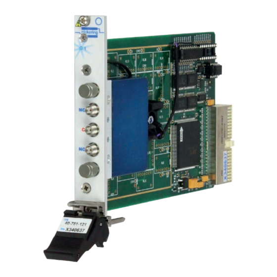
Supported by PXI or LXI Chassis y 3 Year Warranty The 40-781 Microwave switching module consists of one, or two changeover switches capable of switching frequencies to 18 GHz in 50 Ω. It is available with either internal or external terminations and connections are made via front panel mounted high quality SMA coaxial connectors. - Page 10 STATE 1 STATE 1 (DEFAULT) (DEFAULT) STATE 2 STATE 2 40-781-12x Configured as a Terminated 4-Port Bypass 40-781-12x Configured as a 5-Port DP3T Switch Switch (With One External Termination Removed) (With Both External Terminations Removed) Switching Specification RF Specification Configuration:...
- Page 11 0.2 A 1.0 A Mechanical Characteristics 40-781 single SPDT: Single slot 3U PXI (CompactPCI card). 40-781 dual SPDT: Double slot 3U PXI (CompactPCI card). 3D models for all versions in a variety of popular file formats are available on request.
- Page 12 SECTION 1 - TECHNICAL SPECIFICATION pickering Product Order Codes Mating Connectors & Cabling 18 GHz Microwave Relays, 50 Ω SMA For connection accessories for the 40-781 series please 1 x SPDT, Internal Termination 40-781-021 refer to the 90-011D RF Cable Assemblies data sheet...
-
Page 13: Technical Description
We provide a full range of supporting cable and connector solutions for all our switching products—20 connector families with 1200+ products. We offer everything from simple mating connectors to complex cables assemblies and terminal blocks. All assemblies are manufactured by Pickering and are guaranteed to mechanically and electrically mate to our modules. Connectors & Backshells... - Page 14 Terminated SPDT Microwave Relay, 40-781 Programming Pickering provide kernel, IVI and VISA (NI & Keysight) drivers which are compatible with all Microsoft supported versions of Windows and popular older versions. For a list of all supporting operating systems, please see: pickeringtest.com/os...
-
Page 15: Functional Description
PCI Bridge Configuration Terminating Relay Resistors Driver R1-13 +12V 1 or 2 Terminated Control Logic Microwave Relays U3-6 & Module Configuration Figure 2.1 - PXI Terminated Microwave Relay Module 40-781: Functional Block Diagram PXI TERMINATED SPDT MICROWAVE RELAY 40-781 Page 2.1... - Page 16 SECTION 2 - TECHNICAL DESCRIPTION pickering THIS PAGE INTENTIONALLY BLANK PXI TERMINATED SPDT MICROWAVE RELAY 40-781 Page 2.2...
-
Page 17: Installation
Modular products require installation in a suitable PXI/LXI chassis. The module is designed for indoor use only. PREOPERATION CHECKS (UNPACKING) 1. Check the module for transport damage and report any damage immediately to Pickering Interfaces. Do not attempt to install the product if any damage is evident. -
Page 18: Hardware Installation
For a system comprising more than one chassis, turn ON the last chassis in the system followed by the penultimate, etc, and finally turn ON the external controller or chassis containing the system controller. 9. For Pickering Interfaces modular LXI installation there is no requirement to use any particular power up sequence. -
Page 19: Testing Operation
Figure 3.2 - General Soft Front Panel Icon A selector panel will appear, listing all installed Pickering PCI, PXI or LXI switch cards and resistor cards. Click on the card you wish to control, and a graphical control panel is presented allowing operation of the card. - Page 20 SECTION 3 - INSTALLATION pickering THIS PAGE INTENTIONALLY BLANK PXI TERMINATED SPDT MICROWAVE RELAY 40-781 Page 3.4...
-
Page 21: Programming Guide
SECTION 4 - PROGRAMMING GUIDE PROGRAMMING OPTIONS FOR PICKERING INTERFACES PXI MODULES For information on the installation and use of drivers and the programming of Pickering’s products in various software environments, please refer to the Software User Manual. This is available as a download from: https://www.pickeringtest.com/support/software-drivers-and-downloads... -
Page 22: Module Architecture
MODULE ARCHITECTURE The 40-781 module is a single or dual microwave changeover relay with either internal or external termination. In the default state the signal paths are NC to Com and NO terminated as shown in the diagrams below. Externally terminated versions have ports marked “T”... -
Page 23: Programming The Module
SECTION 4 - PROGRAMMING GUIDE pickering PROGRAMMING THE MODULE Here are some simple examples of using the drivers with the 40-781 dual changeover relay module. Using PILPXI To operate a relay the user could use the simple OpBit command or the WriteSub commands OpBit DWORD sub_unit = 1;... - Page 24 SECTION 4 - PROGRAMMING GUIDE pickering THIS PAGE INTENTIONALLY BLANK PXI TERMINATED SPDT MICROWAVE RELAY 40-781 Page 4.4...
-
Page 25: Connector Information
Figure 5.1 - Single Microwave Relay With Internal Terminations 40-781-021: Connector Positions NOTE 1: Only the correct connector series should be mated with these modules. The 40-781 range uses SMA connectors, and the user should only mate the correct type to the module, failure to do so may result in damage to the connector. - Page 26 SECTION 5 - CONNECTOR INFORMATION pickering pickering SPDT Relay 1 Relay 2 Relay 1 SPDT Relay 2 Dual Microwave Relay - Internal Termination Figure 5.2 - Dual Microwave Relay With Internal Terminations 40-781-022: Connector Positions PXI TERMINATED SPDT MICROWAVE RELAY 40-781 Page 5.2...
- Page 27 SECTION 5 - CONNECTOR INFORMATION pickering pickering External Termination SPDT Relay 1 Relay 1 Single Microwave Relay - External Termination External Termination Figure 5.3 - Single Microwave Relay With External Terminations 40-781-121: Connector Positions PXI TERMINATED SPDT MICROWAVE RELAY 40-781 Page 5.3...
- Page 28 SPDT Relay 1 Termination Termination Relay 2 Relay 1 SPDT Relay 2 External External Termination Termination Dual Microwave Relay - External Termination Figure 5.4 - Dual Microwave Relay With External Terminations 40-781-122: Connector Positions PXI TERMINATED SPDT MICROWAVE RELAY 40-781 Page 5.4...
-
Page 29: Trouble Shooting
PCI configuration, highlighting any potential configuration problems. Specific details of all installed Pickering switch cards are included. All the installed Pickering switch cards should be listed in the “Pilpxi information” section - if one or more cards is missing it may be possible to determine the reason by referring to the PCI configuration dump contained in the report, but interpretation of this information is far from straightforward, and the best course is to contact Pickering support: support@pickeringtest.com, if possible... - Page 30 SECTION 6 - TROUBLE SHOOTING pickering THIS PAGE INTENTIONALLY BLANK PXI TERMINATED SPDT MICROWAVE RELAY 40-781 Page 6.2...
-
Page 31: Maintenance Information
For PXI modules which are supported in one of Pickering Interfaces’ Modular LXI Chassis (such as the 60-102B and 60-103B) no module software update is required. If the module was introduced after the LXI chassis was manufactured the module may not be recognized, in this case the chassis firmware may need upgrading. - Page 32 SECTION 7 - MAINTENANCE INFORMATION pickering THIS PAGE INTENTIONALLY BLANK PXI TERMINATED SPDT MICROWAVE RELAY 40-781 Page 7.2...
Need help?
Do you have a question about the 40-781 and is the answer not in the manual?
Questions and answers