Table of Contents
Advertisement
Quick Links
Instruction Manual
D103048X012
Fisher
3024C Diaphragm Actuator
™
Contents
. . . . . . . . . . . . . . . . . . . . . . . . . . . . . . . . .
. . . . . . . . . . . . . . . . . . . . . . . . . . . . . .
. . . . . . . . . . . . . . . . . . . . . . . . . . . . . . . . . .
. . . . . . . . . . . . . . . . . . . . . . . . . . . . . . . .
. . . . . . . . . . . . . . . . . . . . . . . . . . . . . . . . . .
. . . . . . . . . . . . . . . . . . . . . . . . .
. . . . . . . . . . . . . . . . . . . . . . . . . . . . . . . .
. . . . . . . . . . . . . . . . . . . . . . . . . . . . . . . . . . .
. . . . . . . . . . . . . . . . . . . . . . . . . . . . . . .
. . . . . . . . . . . . . . . . . . . . . . . . . . . . . . . . . .
Introduction
Scope of Manual
This instruction manual provides information on installation, adjustment, maintenance, and parts ordering for the
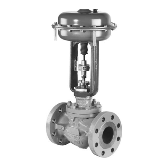
Type 3024C actuator (figure 1) for sizes 30 to 45 and 30E to 45E.
Note
This manual assumes throughout that the valve construction is "push-down-to-close."
Do not install, operate, or maintain a 3024C actuator without being fully trained and qualified in valve,
actuator, and accessory installation, operation, and maintenance. To avoid personal injury or property
damage, it is important to carefully read, understand, and follow all the contents of this manual,
including all safety cautions and warnings. If you have any questions about these instructions, contact
your
Emerson sales office
www.Fisher.com
. . . . . . . . . . . .
. . . . . . . . . . . . . . . .
. . . . . . . . . . . . . . . . . . .
. . . . . . . . . . . . . . . . . . . . . .
before proceeding.
Figure 1. Fisher 3024C Actuator with Sliding-Stem
Valve
1
1
2
3
5
5
8
8
9
12
12
13
15
18
W8488
3024C Actuator
June 2023
Advertisement
Table of Contents

Related Manuals for Emerson Fisher 3024C


Summary of Contents for Emerson Fisher 3024C
-
Page 1: Table Of Contents
3024C Diaphragm Actuator ™ Contents Figure 1. Fisher 3024C Actuator with Sliding‐Stem Valve Introduction ....... . . -
Page 2: Description
Maximum Approximate Weight (with handwheel) 36.4 36.4 55.1 55.1 58.4 62.8 89.3 93.7 Figure 2. Schematic of Fisher 3024C Figure 3. Fisher 3024C Actuator Nameplate AIR PUSHES SPRINGS PUSH STEM DOWN STEM DOWN SPRINGS LIFT AIR LIFTS STEM SEAL STEM UP... -
Page 3: Specifications
1. Effective diaphragm area at 0% valve travel from seat. 2. Based upon 6 bar operating pressure to the diaphragm and valve travel at 0% from seat. This does not consider limitation to the valve such as stem buckling load. Consult your Emerson sales office for details. - Page 4 1. Effective diaphragm area at 0% valve travel from seat. 2. Based on zero operating pressure to the diaphragm and valve travel at 0% from valve seat. This does not consider limitations such as stem buckling load. Consult your Emerson sales office Local Business Partner for details.
-
Page 5: Installation
Responsibility for the safety of process media and the compatibility of valve materials with the process media rests solely with the purchaser and end user. Since some valve body/trim materials combinations are limited in their pressure drop and temperature ranges, do not apply any other conditions to the valve without first contacting your Emerson Automation Solutions sales office. - Page 6 Instruction Manual 3024C Actuator June 2023 D103048X012 Figure 4. Actuator Mounting Components for Assembly with a Valve W8484‐1 WARNING When moving the actuator stem with diaphragm loading pressure use caution to keep hands and tools out of the actuator stem travel path. Personal injury and/or property damage is possible if something is caught between the actuator stem and other parts of the valve assembly.
- Page 7 Instruction Manual 3024C Actuator D103048X012 June 2023 NOTICE Be sure that the length of the actuator stem and the valve stem in the connector (key 50) is equal to or greater than the diameter of that stem. Incomplete engagement of either the valve or actuator stem in the stem connector can result in stripped threads or improper operation.
-
Page 8: Actuator Maintenance
Instruction Manual 3024C Actuator June 2023 D103048X012 k. If the valve travel is not correct repeat the stem connector procedure. Apply approximately 0.5 bar pressure above the upper setting of the spring range to the bottom of the diaphragm, remove the stem connector and then repeat steps d to j. -
Page 9: Assembly
Instruction Manual 3024C Actuator D103048X012 June 2023 2. Bypass the control valve. For a top‐loaded 3024C Air‐to‐Close actuator, reduce the diaphragm air pressure to zero and remove the piping or tubing from the connection in the upper diaphragm casing (key 16). For a bottom loaded 3024C Air‐to‐Open, apply air pressure to the diaphragm to open the valve. - Page 10 Instruction Manual 3024C Actuator June 2023 D103048X012 1. Before starting assembly, apply lithium grease (key 200) to the O‐ring in the bushing (key 6 and key 12). Install the new bushing (key 6) and assemble with the cheese head screws (key 7) onto the lower diaphragm casing (key 1). Use a torque of 0.4 NSm (3 lbfSin).
- Page 11 Instruction Manual 3024C Actuator D103048X012 June 2023 Figure 5. Fisher 3024C Spring Arrangements SIZE 30 AND 30E SIZE 30 AND 30E SIZE 30 AND 30E 7 SPRINGS 3 SPRINGS 5 SPRINGS SPRING LOCATOR SPRING SIZE 34, 34E, AND 40E SIZE 34, 34E, 40, AND 40E...
-
Page 12: Changing The Actuator Action
Instruction Manual 3024C Actuator June 2023 D103048X012 Note Be sure to use the long cap screws (key 21) first, installing them on opposite sides of the diaphragm casing. Tighten them evenly, using a criss‐cross pattern to ensure a proper seal. 5. -
Page 13: Adjustable Travel Stops
Instruction Manual 3024C Actuator D103048X012 June 2023 6. If the handwheel assembly was removed from the actuator yoke, position the assembly within the yoke so that the eight mounting holes on the assembly align with those on the yoke and fit the cap‐screws (key 113) tightening to 28 NSm (20 lbfSft). - Page 14 Instruction Manual 3024C Actuator June 2023 D103048X012 Figure 6. Actuator Dimensions (ACTUATOR REMOVAL) 1Q57491 Actuator Dimensions Refer to figures 6 and 7 and table 5 for dimensions. Table 5. Dimensions M (ATO) M (ATC) Actuator Valve Yoke Boss, Inches Millimeters Size Travel 16 mm...
-
Page 15: Parts Ordering
WARNING Use only genuine Fisher replacement parts. Components that are not supplied by Emerson should not, under any circumstances, be used in any Fisher valve, because they may void your warranty, might adversely affect the performance of the valve, and could cause personal injury and property damage. - Page 16 Instruction Manual 3024C Actuator June 2023 D103048X012 Figure 8. Direct‐Acting Actuator (Air‐to‐Close) 3Q57478...
- Page 17 Instruction Manual 3024C Actuator D103048X012 June 2023 Figure 9. Reverse‐Acting Actuator (Air‐to‐Open) 3Q57479...
-
Page 18: Parts List
Size 30, 30E (10 required) Size 34, 34E, 40, and 40E (15 required) Size 45, 45E (20 required) Note Warning Label Contact your Emerson sales office for Part Ordering information. Nameplate Drive Screw (2 required) Stem Connector Assembly Hex Jam Nut (2 required) - Page 19 Instruction Manual 3024C Actuator D103048X012 June 2023 Figure 10. Side‐Mounted Handwheel for Type 3024C Actuators 1Q57480 Figure 11. Adjustable Up Travel Stop for Sizes 30 to 40E 3Q57478...
- Page 20 Fisher is a mark owned by one of the companies in the Emerson business unit of Emerson Electric Co. Emerson and the Emerson logo are trademarks and service marks of Emerson Electric Co.
Need help?
Do you have a question about the Fisher 3024C and is the answer not in the manual?
Questions and answers