Table of Contents
Advertisement
Quick Links
- 1 General M18 Service Information
- 2 Actuator M18 Manual Hydraulic Operation
- 3 Actuator Power Operation
- 4 Double-Acting Actuator M18 System Fluid Filling
- 5 Spring-Return Actuators M18 System Fluid Filling
- 6 Part No. Va-Ed-005-1120, M18 Assembly Drawing, Sheet 1 of 7
- 7 Part No. Va-Ed-005-1120, M18 Assembly Drawing, Sheet 7 of 7
- Download this manual
Advertisement
Table of Contents

Related Manuals for Emerson Bettis M18


Summary of Contents for Emerson Bettis M18
- Page 1 Installation, Operation and Maintenance Manual VA-DC-000-1879 Rev. 0 April 2021 Bettis M18 Manual Hydraulic Override System For HD, T, and G-Series Pneumatic and Hydraulic Actuators...
- Page 2 Notes Installation, Operation and Maintenance Manual April 2021 VA-DC-000-1879 Rev. 0 This page is intentionally left blank...
-
Page 3: Table Of Contents
Installation, Operation and Maintenance Manual Table of Contents VA-DC-000-1879 Rev. 0 April 2021 Table of Contents Section 1: Introduction General M18 Service Information ..............1 Definitions ....................2 General Safety Information ................2 Fluid Requirements ..................3 Bettis Reference Materials ................3 Section 2: General Information Actuator Power Operation ................ - Page 4 Notes Installation, Operation and Maintenance Manual April 2021 VA-DC-000-1879 Rev. 0 This page is intentionally left blank...
-
Page 5: Section 1: Introduction
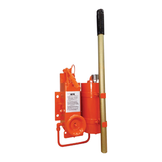
Installation, Operation and Maintenance Manual Section 1: Introduction VA-DC-000-1879 Rev. 0 April 2021 Section 1: Introduction General M18 Service Information 1.1.1 M18 is a compact modular hydraulic override system designed for use with Bettis Double-Acting and Spring-Return Actuators. The system incorporates a piston type hand pump and a fluid reservoir. -
Page 6: Definitions
Section 1: Introduction Installation, Operation and Maintenance Manual April 2021 VA-DC-000-1879 Rev. 0 Definitions WARNING If not observed, user incurs a high risk of severe damage to actuator and/or fatal injury to personnel. CAUTION If not observed, user may incur damage to actuator and/or injury to personnel. NOTE: Advisory and information comments provided to assist maintenance personnel to carry out maintenance procedures. -
Page 7: Fluid Requirements
Low temperature service (-40 °F to +150 °F) Use Exxon Univis J13 or HVI 13 Hydraulic Fluid. Bettis Reference Materials 1.5.1 Bettis M18 System Assembly drawing part number VA-ED-005-1120 (attached to the end of the document). 1.5.2 M18 with auto reset module and remote mounting module use the same assembly drawing VA-ED-005-1120. -
Page 8: Section 2: General Information
Section 2: General Information Installation, Operation and Maintenance Manual April 2021 VA-DC-000-1879 Rev. 0 Section 2: General Information Actuator Power Operation CAUTION Power operation of the actuator with the M18 control knob in any other position than “AUTO” will cause fluid to overflow in the reservoir. 2.1.1 Place the M18 control knob (25 - 200) in the Auto position (middle position). -
Page 9: Section 3: M18 System Fluid Filling Instructions
Installation, Operation and Maintenance Manual Section 3: M18 System Fluid Filling Instructions VA-DC-000-1879 Rev. 0 April 2021 Section 3: M18 System Fluid Filling Instructions Double-Acting Actuator M18 System Fluid Filling Use either Filling Method Number 1 (steps 3.1.2) or Filling Method Number 2 (steps 3.1.3). - Page 10 Section 3: M18 System Fluid Filling Instructions Installation, Operation and Maintenance Manual April 2021 VA-DC-000-1879 Rev. 0 3.1.2.3 Connect the pump motor hose to fitting hole located on the reservoir top end cap (10 - 10), keep pipe plug on the other hole. CAUTION The M18 pump handle lever (20 - 10 - 90) should be in the up position and the pump handle (30 - 70) should be removed from the pump handle lever (20 - 10 - 90).
- Page 11 Installation, Operation and Maintenance Manual Section 3: M18 System Fluid Filling Instructions VA-DC-000-1879 Rev. 0 April 2021 3.1.3 Refilling Method Number 2 Refilling the M18 Manual Hydraulic Override System without using a pump motor. 3.1.3.1 Remove breather (10 - 90) from the top of the reservoir end cap (10 - 10). 3.1.3.2 Remove the bleed plugs from the following locations: NOTE:...
-
Page 12: Spring-Return Actuators M18 System Fluid Filling
Section 3: M18 System Fluid Filling Instructions Installation, Operation and Maintenance Manual April 2021 VA-DC-000-1879 Rev. 0 Spring-Return Actuators M18 System Fluid Filling Actuator position as follows: Apply air to port on power module inner end cap move the actuator to opposition direction and compress the spring. - Page 13 Installation, Operation and Maintenance Manual Section 3: M18 System Fluid Filling Instructions VA-DC-000-1879 Rev. 0 April 2021 3.2.1.4 Start pumping the hydraulic fluid into the system with the pump motor. 3.2.1.5 Stop the pump motor when hydraulic fluid appears as follows: 3.2.1.5.1 G-Series - At the vacant pipe plug port located in the hydraulic override end cap.
- Page 14 Section 3: M18 System Fluid Filling Instructions Installation, Operation and Maintenance Manual April 2021 VA-DC-000-1879 Rev. 0 CAUTION Never allow the M18 reservoir to be pumped dry of hydraulic fluid. 3.2.2.4 Fill reservoir to 1 - 1/2 inches from top of reservoir end cap (10 - 10). NOTE: Add fluid to the reservoir through the open port left vacant in step 3.2.2.1.
-
Page 15: Priming M18 In The Field
Installation, Operation and Maintenance Manual Section 3: M18 System Fluid Filling Instructions VA-DC-000-1879 Rev. 0 April 2021 3.2.3.2 Stroke actuator using power module operating fluid to the fully stroked position and lock in place. 3.2.3.3 Connect pump motor hose to fitting hole on the reservoir top end cap (10 - 10), keep pipe plug on the other hole. -
Page 16: Section 4: M18 Disassembly Instructions
Section 4: M18 Disassembly Instructions Installation, Operation and Maintenance Manual April 2021 VA-DC-000-1879 Rev. 0 Section 4: M18 Disassembly Instructions M18 Pressure Release Instructions NOTE: Shut off and exhaust the operating media from both sides of the actuator’s power cylinder. 4.1.1 Place the M18 control knob (25 - 200) in the Auto position (middle position). -
Page 17: M18 Pump Disassembly Instructions
Installation, Operation and Maintenance Manual Section 4: M18 Disassembly Instructions VA-DC-000-1879 Rev. 0 April 2021 4.2.6 Remove the upper end cap (10 - 10) from center bar assembly (10 - 30). 4.2.7 Remove bottom end cap (10 - 40) from M18 cylinder (10 - 20) and center bar assembly (10 - 30). - Page 18 Section 4: M18 Disassembly Instructions Installation, Operation and Maintenance Manual April 2021 VA-DC-000-1879 Rev. 0 4.3.8 Remove acorn nut (25 - 450) from the control knob (25 - 200) and separate the control knob (25 - 200) from valve stem (20 - 10 - 280). 4.3.9 Refer to assembly drawing sheet 3.
- Page 19 Installation, Operation and Maintenance Manual Section 4: M18 Disassembly Instructions VA-DC-000-1879 Rev. 0 April 2021 4.3.22 Remove the screws (20 - 10 - 100) that retain the back brace (20 - 10 - 130) to the M18 manifold (20 - 10 - 10). 4.3.23 Remove pipe plug (20 - 10 - 210), spring (20 - 10 - 360) and ball (20 - 10 - 350) from manifold (20 - 10 - 10) 4.3.24 Remove the control valve stem (20 - 10 - 280), rotor (20 - 10 - 300), and back plate...
-
Page 20: Section 5: M18 Reassembly Instructions
Section 5: M18 Disassembly Instructions Installation, Operation and Maintenance Manual April 2021 VA-DC-000-1879 Rev. 0 Section 5: M18 Reassembly Instructions M18 General Reassembly Instructions CAUTION Only new seals that are still within the seal’s expectant shelf life should be install into Bettis product being refurbished. -
Page 21: M18 Pump Reassembly Instructions
Installation, Operation and Maintenance Manual Section 5: M18 Reassembly Instructions VA-DC-000-1879 Rev. 0 April 2021 5.2.3 Install reservoir O-ring (10 - 100) over the lip of bottom end cap (10 - 40). 5.2.4 Install cylinder (10 - 20) over the lip of bottom end cap (10 - 40). 5.2.5 Install reservoir O-ring (10 - 100) over the lip of upper end cap (10 - 10) then install entire upper end cap assembly (10 - 10) over the lubricated center bar assembly... - Page 22 Section 5: M18 Reassembly Instructions Installation, Operation and Maintenance Manual April 2021 VA-DC-000-1879 Rev. 0 5.3.13 Install backup rings (20 - 20 - 70) and O-rings (20 - 20 - 60) onto pump cylinder (20 - 10 - 20). NOTE: Refer to assembly drawing sheet 3 Detail D for correct location of these seals.
- Page 23 Installation, Operation and Maintenance Manual Section 5: M18 Reassembly Instructions VA-DC-000-1879 Rev. 0 April 2021 5.3.23 Install the control pointer (25 - 150) onto the control valve stem (20 - 10 - 280). 5.3.24 Install the control knob (25 - 200) onto the control valve stem (20 - 10 - 280). 5.3.25 Retain the control knob (25 - 200) on the control valve stem (20 - 10 - 280) with acorn nut (25 - 450) and lock washer (25 - 460).
-
Page 24: Part No. Va-Ed-005-1120, M18 Assembly Drawing, Sheet 1 Of 7
Appendix Installation, Operation and Maintenance Manual April 2021 VA-DC-000-1879 Rev. 0 Appendix A: List of Drawings Part No. VA-ED-005-1120, M18 Assembly Drawing, Sheet 1 of 7 Figure A-1 Appendix... -
Page 25: Part No. Va-Ed-005-1120, M18 Assembly Drawing, Sheet 2 Of 7
Installation, Operation and Maintenance Manual Appendix VA-DC-000-1879 Rev. 0 April 2021 Part No. VA-ED-005-1120, M18 Assembly Drawing, Sheet 2 of 7 Figure A-2 Appendix... -
Page 26: Part No. Va-Ed-005-1120, M18 Assembly Drawing, Sheet 3 Of 7
Appendix Installation, Operation and Maintenance Manual April 2021 VA-DC-000-1879 Rev. 0 Part No. VA-ED-005-1120, M18 Assembly Drawing, Sheet 3 of 7 Figure A-3 Appendix... -
Page 27: Part No. Va-Ed-005-1120, M18 Assembly Drawing, Sheet 4 Of 7
Installation, Operation and Maintenance Manual Appendix VA-DC-000-1879 Rev. 0 April 2021 Part No. VA-ED-005-1120, M18 Assembly Drawing, Sheet 4 of 7 Figure A-4 Appendix... -
Page 28: Part No. Va-Ed-005-1120, M18 Assembly Drawing, Sheet 5 Of 7
Appendix Installation, Operation and Maintenance Manual April 2021 VA-DC-000-1879 Rev. 0 Part No. VA-ED-005-1120, M18 Assembly Drawing, Sheet 5 of 7 Figure A-5 Appendix... -
Page 29: Part No. Va-Ed-005-1120, M18 Assembly Drawing, Sheet 6 Of 7
Installation, Operation and Maintenance Manual Appendix VA-DC-000-1879 Rev. 0 April 2021 Part No. VA-ED-005-1120, M18 Assembly Drawing, Sheet 6 of 7 Figure A-6 Appendix... -
Page 30: Part No. Va-Ed-005-1120, M18 Assembly Drawing, Sheet 7 Of 7
Appendix Installation, Operation and Maintenance Manual April 2021 VA-DC-000-1879 Rev. 0 Part No. VA-ED-005-1120, M18 Assembly Drawing, Sheet 7 of 7 Figure A-7 Appendix... - Page 31 Installation, Operation and Maintenance Manual Notes VA-DC-000-1879 Rev. 0 April 2021 This page is intentionally left blank...
- Page 32 Tianjin 301700 Holland Fasor 6 P. R. China Székesfehérvár 8000 The Emerson logo is a trademark and service mark of Emerson Electric Co. T +86 22 8212 3300 Hungary Bettis is a mark of one of the Emerson family of companies.
Need help?
Do you have a question about the Bettis M18 and is the answer not in the manual?
Questions and answers