
Related Manuals for Emerson AMS 6500 ATG


Summary of Contents for Emerson AMS 6500 ATG
- Page 1 Operating Manual MHM-97891, Rev 1.01 April 2025 AMS 6500 ATG A6500-CP Com Card Pro...
- Page 2 Information in this document is subject to change without notice and does not represent a commitment on the part of Emerson. The information in this manual is not all-inclusive and cannot cover all unique situations.
- Page 3 Opmerking m.b.t. installatie van elektrische meet circuits in explosiegevaarlijke omgeving Dient de installatie van elektrische meet circuits in een explosiegevaarlijke omgeving te geschieden, moet men toezien dat de in de gebruikshandleiding opgenomen installatieinstructies worden nageleefd. Bij taalkundige problemen gelieve contact op te nemen met de fabrikant, deze zal u vervolgens een vertaling in de taal van het gebruiksland doen toekomen.
- Page 4 Piezīme par mērīšanas ķēžu instalēšanu sprādziena bīstamās zonās. Ja mērīšanas ķēde jāuzstāda sprādzienbīstamā zonâ, ir jāievēro lietošanas instrukcijā dotie instalēšanas norādījumi. Ja rodas kādas valodas grūtības, lūdzu griezieties pie izgatavotāja firmas, kas Jums nosūtīs nozīmīgâko nodaļu tulkojumus lietotāja valsts valodā. Emerson epro GmbH Jöbkesweg 3 48599 Gronau...
-
Page 5: Table Of Contents
1.4 Incoming goods inspection......................8 1.5 Technical support..........................8 1.6 Storage and transport........................9 1.7 Disposal of the device........................9 1.8 China RoHS Compliance........................9 1.9 CCC Certification – AMS 6500 ATG....................10 Chapter 2 Safety instructions....................... 11 2.1 Using the device..........................11 2.2 Owner's responsibility........................11 2.3 Radio interference.......................... - Page 6 6.6.2 Reload a configuration........................ 43 6.7 Transfer of an A6500-CC configuration to an A6500-CP card............44 6.7.1 AMS 6500 ATG system with A6500-CC – configuration transfer via file........44 6.7.2 AMS 6500 ATG system with A6500-CC – configuration transfer from Workspace......45 Chapter 7 Redundancy.........................
-
Page 7: Chapter 1 General
Operating Manual General MHM-97891 April 2025 General Using this manual This manual contains information concerning the use of the device. Read the operating manual completely before installing and using the device. Comply with all safety instructions. This operating manual applies for A6500-CP Com Cards Pro with hardware revisions and software versions listed in Table 1-1. -
Page 8: Liability And Guarantee
Liability and guarantee Emerson is not liable for damages that occur due to improper use. Proper use also includes the knowledge of, and compliance with, this document. Customer changes to the device that have not been expressly approved by Emerson will result in the loss of guarantee. -
Page 9: Storage And Transport
April 2025 +63 2 8702 1111 (Asia Pacific, Europe, and Middle East) Email Guardian.GSC@Emerson.com http://www.emerson.com/en-us/contact-us To search for documentation, visit http://www.emerson.com. To view toll free numbers for specific countries, visit http://www.emerson.com/ technicalsupport. Note If the equipment has been exposed to a hazardous substance, a Material Safety Data Sheet (MSDS) must be included with the returned materials. -
Page 10: Ccc Certification - Ams 6500 Atg
The names and contents of hazardous substances can be found in chapter "Certificates". CCC Certification – AMS 6500 ATG With the announcement of the Chinese market regulation authority SAMR (State Administration for Market Regulation), a Compulsory Product Certification (CCC certification) is mandatory for many explosion protection products. -
Page 11: Chapter 2 Safety Instructions
Operating Manual Safety instructions MHM-97891 April 2025 Safety instructions To ensure safe operation, carefully follow all the instructions in this manual. The correct and safe use of this device requires that both operating and service personnel understand and comply with general safety guidelines and observe the special safety comments listed in this manual. -
Page 12: Esd Safety
Safety instructions Operating Manual April 2025 MHM-97891 other peripheral devices that are not properly shielded against radio interference, disturbances and radio interferences may occur. ESD safety DANGER Internal components can be damaged or destroyed due to electrostatic discharge (ESD) during the handling of the device. Take suitable precautions before handling the device to prevent electrostatic discharges through the electronics. -
Page 13: Application And Design
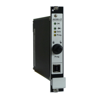
Application and design Application The A6500-CP Com Card Pro is a component of the AMS 6500 ATG system and mandatory for communication with all cards of the system such as the A6500-UM Universal Measuring Card, the A6500-TP Temperature Process Card, and the A6500-RC Relay Card. - Page 14 C. Handle for pulling the monitor from the rack; labeled with the serial number on a small sticker. D. Slot for micro SD card (use only Emerson authorized micro SD cards) E. Switch for data diode control F. RJ45 Ethernet connector for configuration and data exchange (LAN 1) G.
- Page 15 Operating Manual Application and design MHM-97891 April 2025 Figure 3-2: Front view A. Mounting screws B. green OK LED: Card power and status indication (see Table 3-2) C. green Data Diode LED: indicates state (on or off) of the data diode (see Table 3-2) D.
- Page 16 3. Fast flashing of the OK LED for approximately 8 seconds. AMS 6500 ATG system with redundant communication cards: At least one key-switch is in the locked position. AMS 6500 ATG system with redundant communication cards: Both key-switches are in the unlocked position.
-
Page 17: Chapter 4 Installation
If using an A6500-xR System Rack with two communication card slots, install a single A6500-CP Com Card Pro in either the left or right slot. Emerson recommends to use the left slot (A6500-SR: CD13 or A6500-RR: CD12) for single communication card installations and for the primary communication card in redundant systems the right slot (A6500-SR: CD14 or A6500-RR: CD13). -
Page 18: Ethernet And Usb Connection
Installation Operating Manual April 2025 MHM-97891 CAUTION Always use communication cards of the same type for building a redundant communication. Do not mix A6500-CC and A6500-CP cards. Ethernet and USB connection The A6500-CP Com Card Pro has two Ethernet interfaces for connecting the card to Ethernet networks. -
Page 19: Micro Sd Card
The A6500-CP Com Card Pro is equipped with a slot for a micro SD card (see Figure 3-1 location). A micro SD card is required for storing events and for AMS 6500 ATG systems with data collection function. If a communication card is not yet equipped with a micro SD... -
Page 20: Replace A Micro Sd Card
Installation Operating Manual April 2025 MHM-97891 3. Place the micro SD card with contacts downwards into the slot. The card fits only in one direction. 4. Close the cover. 5. Slide the cover in direction lock (see Figure 4-1) to lock the cover. 4.2.2 Replace a micro SD card Procedure... - Page 21 Operating Manual Installation MHM-97891 April 2025 Activate data diode CAUTION Any work on the system may impair machine protection. Follow these steps to activate the data diode. Skip the first two steps if the A6500-CP card is not yet installed. 1.
- Page 22 Installation Operating Manual April 2025 MHM-97891 Figure 4-3: Data diode LED A. Green data diode LED: on Deactivate data diode CAUTION Any work on the system may impair machine protection. Follow these steps to deactivate the data diode. Skip the first two steps if the A6500-CP card is not yet installed.
-
Page 23: Hazardous Location Installation
Operating Manual Hazardous location installation MHM-97891 April 2025 Hazardous location installation The ex-approval of the A6500-CP Com Card Pro is only valid if the communication card is installed in an A6500-xR System Rack. See chapter "Hazardous location installation" of the A6500-xR System Racks operating manual (MHM-97877) for details. -
Page 24: Chapter 6 Configuration
Computer with Microsoft Windows 10 or Microsoft Windows 11. Note At the first configuration of an AMS 6500 ATG system use the USB interface to set the IP address for the network connection. The default IP address of a new A6500-CP Com Card Pro installed in the left slot is 192.168.1.100 and 192.168.1.101 for a new A6500-CP in the... -
Page 25: Online Configuration Overview
8. Open the saved configuration file (window File, menu item Open). 9. Send the configuration to the communication card. 10. Switch back the key-switch to the locked position to protect the AMS 6500 ATG system against unauthorized changes. 11. Close AMS Machine Studio and disconnect the connection to the A6500-CP Com Card Pro. - Page 26 The enabled system programming is indicated by: • A switched on Prog. LED • An unlock symbol in the device tree behind the related AMS 6500 ATG system • A status information in the online view • Modbus register and OPC UA data point...
- Page 27 An enabled system programming is indicted by: • A switched on Prog. LED • An unlock symbol in the device tree behind the related AMS 6500 ATG system • A status information in the online view • Modbus register and OPC UA data point...
-
Page 28: Start Of An Offline Card Configuration
Configuration Operating Manual April 2025 MHM-97891 Figure 6-2: Key-switch in unlocked position A. Program LED (Prog. LED) B. Key-switch in unlocked position C. Indication in AMS Machine Studio D. Online view of the A6500-CP cards Start of an offline card configuration Procedure 1. -
Page 29: Start Of An Online Card Configuration
Operating Manual Configuration MHM-97891 April 2025 Figure 6-4: Card selection The communication card is added to the list below Workspace. 3. Select A6500-CP from the Workspace list and click Configure (see Figure 6-5). Figure 6-5: Configure A. New A6500-CP card B. -
Page 30: Configuration Of An Already Existing Card
Configuration Operating Manual April 2025 MHM-97891 Figure 6-6: Select a Com Card for online configuration A. Selected A6500-CP card. B. Button Configure for opening the configuration editor. The dialog New configuration opens if an unconfigured card has been selected, otherwise the editor with the configuration opens. 2. -
Page 31: Ribbon Command Bar
Operating Manual Configuration MHM-97891 April 2025 Figure 6-7: Configuration editor A. Ribbon command bar B. Card name and position within the rack (only visible at connected racks, for example: R1 = Rack 1; S13 = Slot 13) C. List of configuration pages D. - Page 32 Delete configuration CAUTION The configuration on the card will be deleted. In AMS 6500 ATG systems with redundant A6500-CP cards, the configuration of both A6500-CP cards is deleted, regardless of which A6500-CP card is selected in the device tree.
- Page 33 Selectable cards are in bold. Figure 6-15: Selection dialog – other card 1. Expand the listed AMS 6500 ATG systems and racks to see the cards available for selection. 2. Click a card to select it. A selected card is highlighted blue.
- Page 34 Configuration Operating Manual April 2025 MHM-97891 Figure 6-16: Select dialog – history/drafts 1. Click a configuration to select it. A selected configuration is highlighted blue. See Show History/Drafts for an explanation of the different types (Draft Config, Running Config, and Running Config (historic)).
- Page 35 Operating Manual Configuration MHM-97891 April 2025 3. Click the buttons with the dotted line within the Report settings area to browse for logos. Logos with file format "png" or "jpg" can be selected. 4. Click OK to confirm your settings. The window closes.
- Page 36 Configuration Operating Manual April 2025 MHM-97891 Figure 6-20: History The right part of Figure 6-20 shows the configuration history. The individual files are marked with date, time, and type: Draft Config A saved preliminary configuration file which has not yet been sent to the card.
-
Page 37: Basic
Operating Manual Configuration MHM-97891 April 2025 6.5.2 Basic Enter general machine and plant information (see Figure 6-23). Figure 6-23: Basic Rack name Enter the name or a short description of the Rack. Card name Enter the card name or short description of the measurement. Machine Enter the machine designation. - Page 38 Configuration Operating Manual April 2025 MHM-97891 configuration pages of further functions assigned to LAN 1 (see Auto discovery Machine Studio). Note The configuration requires an IP address for the secondary card even if only the primary card is used. If one communication card is used enter the same IP address, subnet mask, and gateway for the primary and secondary card.
-
Page 39: Auto Discovery
Operating Manual Configuration MHM-97891 April 2025 Secondary A6500-CP card (location of the card) IP address Enter here the IP address (IP4 standard) for the upper Ethernet connector of the communication card installed in the right communication card slot (A6500-SR: slot 14 or A6500-RR: slot 13). Subnet Enter here the subnet mask for the upper Ethernet connector of the mask... - Page 40 Configuration Operating Manual April 2025 MHM-97891 Figure 6-27: List of discovered hosts Broadcast Enter here the repetition time for the broadcast. repetition time [s] Machine Studio Configure the configuration interface for LAN 1 (see Figure 6-28). Define a configuration interface if you want to allow additional AMS Machine Studios to change the configuration settings.
-
Page 41: Lan 2
April 2025 Port Enter here the TCP port for the network communication. Ensure that the port entered is unique and not used by another AMS 6500 ATG interface. Note Sending of a configuration with a changed port causes a disconnect of all connections to AMS Machine Studio. -
Page 42: Send And Reload A Configuration
1. Ensure that there is an online connection between the A6500-CP Com Card Pro and AMS Machine Studio running on a computer. AMS Machine Studio will automatically establish an online connection to the cards of the AMS 6500 ATG system as soon as there is a physical connection through the MHM-97891, Rev. 1.01... -
Page 43: Reload A Configuration
Set time in the ribbon command bar. This is not necessary if the time is automatically synchronized with an SNTP server. 4. Switch back the key-switch to the locked position to protect the AMS 6500 ATG system against unauthorized changes. -
Page 44: Transfer Of An A6500-Cc Configuration To An A6500-Cp Card
Click Close configuration to close the configuration editor. 3. Disconnect from the AMS 6500 ATG system with the A6500-CC Com Card. 4. Connect to the AMS 6500 ATG system with the A6500-CP Com Card Pro to which the configuration needs to be transferred. -
Page 45: Ams 6500 Atg System With A6500-Cc - Configuration Transfer From Workspace
8. Disconnect from the AMS 6500 ATG system with the A6500-CC Com Card. 9. Connect to the AMS 6500 ATG system with the A6500-CP Com Card Pro to which the configuration needs to be transferred. Log in as an Operator or an Administrator. - Page 46 Configuration Operating Manual April 2025 MHM-97891 Enable system programming with A6500-CP communication card Enable system programming with redundant A6500-CP communication cards. MHM-97891, Rev. 1.01...
-
Page 47: Chapter 7 Redundancy
Operating Manual Redundancy MHM-97891 April 2025 Redundancy Note Ensure that both A6500-CP Com Cards Pro used for the redundancy have the same firmware version installed. Do not build a redundancy by mixing communication cards of different types (A6500-CC and A6500-CP is not possible). Install two A6500-CP Com Cards Pro to establish a system with redundant communication. - Page 48 Redundancy Operating Manual April 2025 MHM-97891 • The left communication card slot is the primary communication card slot. The right communication card slot is the secondary communication card slot. • Both communication cards are linked through the backplane. • One communication card communicates through the backplane with the installed cards (active on the bus).
-
Page 49: Configuration
Operating Manual Redundancy MHM-97891 April 2025 Figure 7-2: Example: Primary card fails A. System Rack Bus B. Primary Master (A6500-SR: slot 13 or A6500-RR: slot 12 ) C. Secondary Master (A6500-SR: slot 14 or A6500-RR: slot 13) D. Communication card link E. - Page 50 Redundancy Operating Manual April 2025 MHM-97891 Table 7-1: Parameters for redundancy (continued) Configuration Page Parameter Secondary subnet mask Secondary gateway LAN 2 Primary IP address Primary subnet mask Primary gateway Secondary IP address Secondary subnet mask Secondary gateway Modbus Primary master address Secondary master address Modbus RTU Bus termination primary master...
-
Page 51: Manual Change Of Active/Passive State
Operating Manual Redundancy MHM-97891 April 2025 Figure 7-3: Copy of configuration A. At power on, communication cards installed in both slots: The configuration file of the communication card in left slot is automatically copied to the card in the right slot. B. - Page 52 Redundancy Operating Manual April 2025 MHM-97891 For the state of the A6500-CP Com Card Pro (active or passive) see Online View → Overview → Redundancy or Modbus Holding register / OPC UA data point Info.IsActiveCard. Table 7-2: Modbus Holding register – Active/passive state Register Type Name...
- Page 53 Operating Manual Redundancy MHM-97891 April 2025 Register Type Name Description 64005 16 Bit Integer Reboot Com Card Use this register to right send a command to reboot the A6500-CP in the right communication card slot. -1: Waiting for command 0: Busy 1: Send reboot OPC UA OPC UA data point Command.RebootComCard, available if Configuration...
-
Page 54: Chapter 8 Online View
Online view Operating Manual April 2025 MHM-97891 Online view Select the System Rack in the device tree of AMS Machine Studio to open an overview of the connected System Rack in the online view. See Figure 8-1. Figure 8-1: System Rack overview A. -
Page 55: Overview
Operating Manual Online view MHM-97891 April 2025 Overview Figure 8-3 shows the Overview page. Figure 8-3: Overview A. Column with general states B. Column with states related to LAN 1 (upper Ethernet port) C. Column with states related to LAN 2 (lower Ethernet port) D. -
Page 56: Lan 1 And Lan 2 States
Key locked The physical state of the key-switch is shown. The key-switch in locked position is indicated with a blue solid circle. Otherwise this circle is gray. Config. The enabled programming of the AMS 6500 ATG system is indicated with a allowed blue solid circle. In redundant systems, the key-switch of both A6500-CP cards must be in the unlocked position to enable programming of the system. -
Page 57: External Interfaces
Operating Manual Online view MHM-97891 April 2025 Connected Indicates a connection between the interface and the communication card. An established connection is indicated with a blue solid circle. Otherwise the circle is gray. In redundant systems the shown number of connected clients is the number of connected active communication cards. -
Page 58: Details
The supply voltage is out of the Check the supply voltage of the with x permissible range. AMS 6500 ATG system in which the A6500-CP card is installed and reestablish the voltage supply or take measures to ensure a stable voltage supply of ideally 24.0 V DC. -
Page 59: General States
Operating Manual Online view MHM-97891 April 2025 Card health Card health information. Service This graphical object contains statistical values and temperature information. Up time Days in operation since the last power on. This counter is reset at each power on. Operation time Days in operation since the first power on. -
Page 60: Lan 1 And Lan 2
Online view Operating Manual April 2025 MHM-97891 8.2.3 LAN 1 and LAN 2 Figure 8-6: Details – LAN 1 Figure 8-7: Details – LAN 2 LAN 1, LAN 2, OPC UA, Modbus TCP, Machine Studio, ATG service, Web server, and Auto discovery LAN 1 and LAN 2 states. -
Page 61: Online Commands
Operating Manual Online view MHM-97891 April 2025 Modbus RTU interface and USB interface These graphic objects contain a communication error counter and indicate the communication speed. Online commands The A6500-CP card related commands are described. For description of all other buttons of the ribbon command bar see operating manual "AMS Machine Studio - General Functions"... -
Page 62: Functions And Applications
System Rack (A6500-SR or A6500-RR). This is the minimum setup for an AMS 6500 ATG system as the communication card is required for the configuration of the complete system. -
Page 63: Redundant A6500-Cp Card Communication
Biasing resistors secondary master Box not checked Redundant A6500-CP card communication Two communication cards installed in the AMS 6500 ATG system are required for redundancy. The following communication interfaces are redundant: • Internal bus interface for communication between cards and communication cards •... - Page 64 Functions and applications Operating Manual April 2025 MHM-97891 Figure 9-1: Redundant Modbus RTU with identical device address A. Cards B. Internal bus lines C. Primary master D. Secondary master E. Modbus RTU primary master F. Modbus RTU secondary master (Primary master address = Secondary master address) Table 9-2 shows an example configuration for redundant Modbus RTU communication with identical master addresses.
-
Page 65: Modbus Rtu - Communication Cards With Unique Device Addresses
Operating Manual Functions and applications MHM-97891 April 2025 Table 9-2: Redundant card communication – Example configuration Modbus RTU with same address (continued) Configuration page Parameter Value Configuration Services → Modbus Modbus Primary master address Secondary master address Read response for unmapped register Illegal data address Write response for unmapped register Illegal data address... - Page 66 Functions and applications Operating Manual April 2025 MHM-97891 Figure 9-2: Redundant Modbus RTU with unique device addresses A. Cards B. Internal bus lines C. Primary master D. Secondary master E. Modbus RTU primary master F. Modbus RTU secondary master (Primary master address ≠ Secondary master address) Table 9-3 shows an example configuration for redundant Modbus RTU communication with unique master addresses.
-
Page 67: Modbus Over Tcp/Ip - Both Cards Within The Same Lan
Operating Manual Functions and applications MHM-97891 April 2025 Table 9-3: Redundant card communication – Example configuration Modbus RTU with unique device addresses (continued) Configuration page Parameter Value Configuration Services → Modbus Modbus Primary master address Secondary master address Read response for unmapped register Illegal data address Write response for unmapped register Illegal data address... - Page 68 Functions and applications Operating Manual April 2025 MHM-97891 Figure 9-3: Modbus over TCP /IP – Both cards within the same LAN A. Cards B. Internal bus lines C. Primary master D. Secondary master E. Modbus TCP primary master F. Modbus TCP secondary master Table 9-4 shows an example configuration for redundant Modbus over TCP/IP with both communication cards connected to the same LAN.
-
Page 69: Modbus Over Tcp/Ip - Two Separate Lans
Operating Manual Functions and applications MHM-97891 April 2025 Table 9-4: Modbus over TCP /IP – Example configuration both cards within the same (continued) Configuration page Parameter Value Secondary gateway Configuration Services → Modbus Modbus Primary master address 1 (also required for Modbus over TCP/IP) Secondary master address 2 (also required for Modbus... - Page 70 Functions and applications Operating Manual April 2025 MHM-97891 Figure 9-4: Modbus over TCP/IP – Two separate LANs A. Cards B. Internal bus lines C. Primary master D. Secondary master E. Modbus TCP primary master F. Modbus TCP secondary master Table 9-5 shows an example configuration for redundant Modbus over TCP/IP whereat the communication cards are connected to different LANs.
-
Page 71: Secure Start Up
Operating Manual Functions and applications MHM-97891 April 2025 Table 9-5: Modbus over TCP /IP – Example configuration with communication cards connected to different LANs (continued) Configuration page Parameter Value Secondary gateway Configuration Services → Modbus Modbus Primary master address 1 (also required for Modbus over TCP/IP) Secondary master address 2 (also required for Modbus... -
Page 72: Chapter 10 Maintenance
Maintenance Operating Manual April 2025 MHM-97891 Maintenance The A6500-CP Com Card Pro does not require any maintenance during normal operation. MHM-97891, Rev. 1.01... -
Page 73: Replace A Communication Card
Operating Manual Replace a communication card MHM-97891 April 2025 Replace a communication card Follow this procedure if a communication card needs to be replaced. For example, due to a defect. The communication card is hot-swappable. CAUTION Any work on the system may impair machine protection. Procedure 1. -
Page 74: Chapter 12 Technical Data
Technical data Operating Manual April 2025 MHM-97891 Technical data Only specifications with indicated tolerances or limit values are binding. Data without tolerances or without error limits are informative data and not guaranteed. Technical modification, especially of the software, are subject to changes without notice. If not specified otherwise, all data are referred to an environmental temperature of +25°C. -
Page 75: Mechanical Design And Environmental Conditions
Operating Manual Technical data MHM-97891 April 2025 Modbus interface Bus termination internal line polarization and termination switchable by configuration Data rate 9600, 19.2, or 38.4 kBaud default 19.2 kBaud 12.3 Mechanical design and environmental conditions Mechanical design Rack slot 3RU/4HP Material front panel aluminum, clear anodized Board dimensions... - Page 76 Technical data Operating Manual April 2025 MHM-97891 Environmental conditions Relative humidity 5 to 95% noncondensing Shock 150 m/s according to IEC 60068-2-27, 4000 shocks per axis Vibration 0.15 mm 10 to 55Hz 20 m/s 55 to 150Hz according to IEC 60068-2-6, float sinus, three axis Operating altitude <2000 m...
- Page 77 Operating Manual Technical data MHM-97891 April 2025 Figure 12-1: Dimensions A. 3 RU B. 4 HP All dimensions in mm MHM-97891, Rev. 1.01...
-
Page 78: Chapter 13 Certificates
Certificates Operating Manual April 2025 MHM-97891 Certificates MHM-97891, Rev. 1.01... - Page 79 Operating Manual Certificates MHM-97891 April 2025 MHM-97891, Rev. 1.01...
- Page 80 Certificates Operating Manual April 2025 MHM-97891 MHM-97891, Rev. 1.01...
- Page 81 Operating Manual Certificates MHM-97891 April 2025 MHM-97891, Rev. 1.01...
- Page 82 Certificates Operating Manual April 2025 MHM-97891 MHM-97891, Rev. 1.01...
-
Page 83: Appendix A Card Related System Events
Operating Manual Card related system events MHM-97891 April 2025 Card related system events The possible system events provided by the A6500-CP card are listed in Table A-1. See column Cross reference / Note for further event related information. See Machine Studio –... - Page 84 Card related system events Operating Manual April 2025 MHM-97891 Table A-1: Card events (continued) Event Cross reference / Note ATG Service interface activated LAN 1 and LAN 2 states, see State of the interface connection ATG Service interface deactivated ATG Service connected ATG Service disconnected Hardware error Replace the card...
-
Page 85: Index
Operating Manual Index MHM-97891 April 2025 Index AMS Machine Studio 42, System program status 25, ATG-Service Auto discovery 39, Technical support CCC Certification Configuration send Web server Data diode 20, Device tree Disposal IP Address 37, Key-switch 25, 26, LAN 67, LAN 1 LAN 2 License... - Page 86 The Emerson logo is a trademark and service mark of Emerson Electric Co. The AMS logo is a mark of one of the Emerson family of companies. All other marks are the property of their respective owners.
Need help?
Do you have a question about the AMS 6500 ATG and is the answer not in the manual?
Questions and answers