Table of Contents
Advertisement
Quick Links
Advertisement
Table of Contents

Summary of Contents for Emerson Shafer
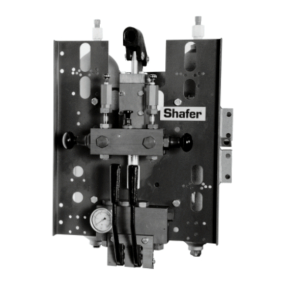
- Page 1 Installation, Operation and Maintenance Manual PBC-01102001 Rev. A January 2001 Shafer Poppet Block Control USASI SCHEMATIC Normally closed, double three-way poppet valve, with open exhaust, manual and pilot actuated. POWER EXHAUST OR PILOT RETURN OIL...
-
Page 3: Table Of Contents
Installation, Operation and Maintenance Manual Table of Contents PBC-01102001 Rev. A January 2001 Table of Contents Section 1: Introduction Basic Construction ...................4 Operation ......................4 Section 2: Basic Check Out Procedures Check No.1 ......................7 Check No. 2 .....................7 Section 3: Bill of Material Section 4: Reconditioning and Assembly Reconditioning ....................9 Assembly ......................9... -
Page 4: Section 1: Introduction
PBC-01102001 Rev. A Section: 1 Introduction The poppet block is the heart of most Shafer control systems. A double three-way, manual and pilot actuated, control valve is designed to provide selective directional operation of Shafer actuators. The poppet block control may direct power gas to a set of gas/hydraulic tanks (generating hydraulic pressure for powering valve actuators), or it may direct central hydraulic system pressure directly into a valve actuator. - Page 5 Installation, Operation and Maintenance Manual Section 1: Introduction PBC-01102001 Rev. A January 2001 Pilot pressure to the pilot piston (5) illustrates force applied to the piston seating the exhaust poppet and simultaneously unseating the power poppet. Power gas is directed through tank port "B".
- Page 6 Section 1: Introduction Installation, Operation and Maintenance Manual January 2001 PBC-01102001 Rev. A Movement of the lever (7) illustrates force applied by the stem (6), seating the exhaust poppet and simultaneously unseating the power poppet. Power gas is directed through tank port "A".
-
Page 7: Section 2: Basic Check Out Procedures
January 2001 Section: 2 Basic Check Out Procedures The following two checks illustrate proper working functions of the Shafer Poppet Block. Failure of any of these procedures may result in operating problems with the valve actuator. This description is for gas service, but the unit can also be used in hydraulic service. -
Page 8: Section 3: Bill Of Material
Section 3: Bill of Material Installation, Operation and Maintenance Manual January 2001 PBC-01102001 Rev. A Section: 3 Bill of Material Figure 7 15 17 10 16 1/8 NPTF PILOT PORT 1/4 NPTF (OPTIONAL) POWER STORAGE TANK 20 21 1/2 NPTF 1/2 NPTF POWER PORT EXHAUST PORT... -
Page 9: Section 4: Reconditioning And Assembly
Installation, Operation and Maintenance Manual Section 4: Reconditioning and Assembly PBC-01102001 Rev. A January 2001 Section: 4 Reconditioning and Assembly Reconditioning Power poppets have a raised boss for poppet spring engagement which may be grasped with pliers for easy removal. Do not pry poppets off pins with a screwdriver as damage to seats in the poppet block may result. -
Page 10: Section 5: Disassembly Of The Poppet Block
Section 5: Disassembly of the Poppet Block Installation, Operation and Maintenance Manual January 2001 PBC-01102001 Rev. A Section: 5 Disassembly of the Poppet Block Figure 9 18 3 3 18 18 4 Disassembly and Poppet Block... - Page 11 Installation, Operation and Maintenance Manual Section 5: Disassembly of the Poppet Block PBC-01102001 Rev. A January 2001 CAUTION Turn off power gas, bleed off gas volume in power storage tank if so equipped, depress manual poppet - activating stem to vent any entrapped pressures. NOTE: Isolate and disarm control.
- Page 13 ©2017 Emerson. All rights reserved. F +65 6268 0028 Building #230 Székesfehérvár 8000 The Emerson logo is a trademark and service mark of Emerson Electric Co. No. 1 Lai Yuan Road Hungary Shafer is a mark of one of the Emerson family of companies.


Need help?
Do you have a question about the Shafer and is the answer not in the manual?
Questions and answers