Emerson Rosemount 3051S Manual
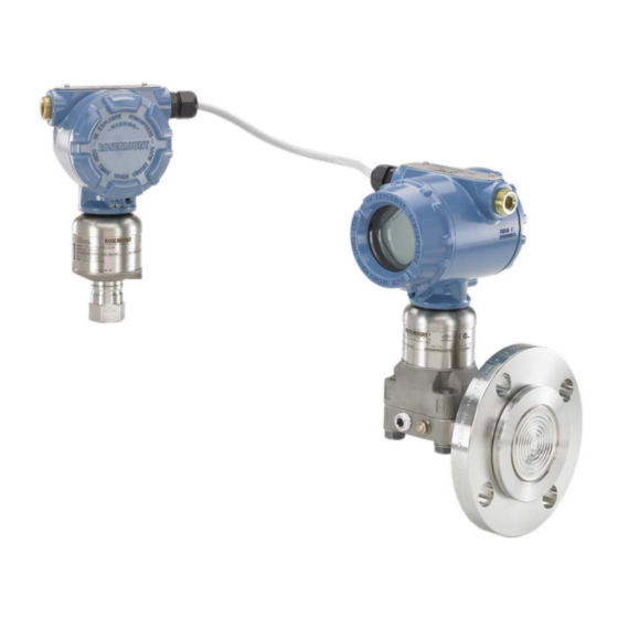
Electronic remote sensor system
Hide thumbs
Also See for Rosemount 3051S:
- Reference manual (240 pages) ,
- Manual (96 pages) ,
- Quick start manual (60 pages)

Related Manuals for Emerson Rosemount 3051S


Summary of Contents for Emerson Rosemount 3051S
- Page 1 Reference Manual 00809-0100-4804, Rev DB March 2024 Rosemount ™ 3051S Electronic Remote Sensor (ERS) ™ System...
- Page 2 Do not attempt to loosen or remove flange bolts while the Rosemount system is in service. Replacement equipment or spare parts not approved by Emerson for use as spare parts could reduce the pressure retaining capabilities of the transmitter and may render the instrument dangerous.
- Page 3 The products described in this document are NOT designed for nuclear-qualified applications. Using non-nuclear qualified products in applications that require nuclear-qualified hardware or products may cause inaccurate readings. For information on Emerson nuclear-qualified products, contact your local Emerson Sales Representative. NOTICE Improper assembly of manifolds to traditional flange can damage the device.
-
Page 5: Table Of Contents
67 5.3 LCD display diagnostics......................67 5.4 ERS System troubleshooting....................76 5.5 Measurement quality status....................78 Chapter 6 Safety Instrumented Systems (SIS) requirements..............79 6.1 Safety Instrumented Systems (SIS) Certification..............79 Appendix A Reference data........................83 A.1 Product Certifications....................... 83 A.2 Ordering information, specifications, and drawings............83 www.emerson.com... - Page 6 Contents Reference Manual March 2024 00809-0100-4804 www.emerson.com...
-
Page 7: Chapter 1 Introduction
Reference Manual Introduction 00809-0100-4804 March 2024 1 Introduction 1.1 Product recycling/disposal Consider recycling equipment and packaging. Dispose of the product and packaging in accordance with local and national legislation. www.emerson.com... - Page 8 Introduction Reference Manual March 2024 00809-0100-4804 www.emerson.com...
-
Page 9: Chapter 2 Configuration
3-13. The communication device or AMS Device Manager may be connected at PWR/COMM on the terminal block of the Rosemount 3051S ERS Primary Transmitter, across the load resistor, or at any termination point in the signal loop. The communication device or AMS Device Manager will search for a HART -compatible ®... - Page 10 Damping can be set independently for the Differential Pressure, P Pressure, and P Pressure measurements. Damping values can be set anywhere from 0 to 60 seconds. 2.4.4 Variable mapping Fast keys 2, 1, 1, 3 Select which ERS System parameters to assign to each HART variable. ® www.emerson.com...
- Page 11 , can also be used to convert each ™ of the variables to a separate 4–20 mA analog output signal. These variables can also be accessed wirelessly by using an Emerson Wireless THUM Adapter. The following system ™ parameters can be assigned to the 2...
- Page 12 High 20.8 mA ≥ 21.75 mA NAMUR-Compliant Switch Position Saturation Level Alarm Level 3.8 mA ≤ 3.6 mA High 20.5 mA ≥ 22.5 mA Custom Switch Position Saturation Level Alarm Level 3.7 — 3.9 mA 3.54 — 3.8 mA www.emerson.com...
-
Page 13: Additional Configuration
HART communication. A communication device, AMS Device Manager, or the control system may request any of the information that is normally available while the system is in Burst mode. Configure Burst mode To have the system configured to communicate in burst mode: www.emerson.com... - Page 14 Note A transmitter in multidrop mode with Loop Current Mode disabled has the analog output fixed at 4 mA. Communication between the host and the transmitters takes place digitally, and the analog output on each transmitter is deactivated. www.emerson.com...
- Page 15 This will cause the analog output of the system to be fixed at 4 mA. Disable multidrop configuration To configure a system with the factory default point-to-point communication: Procedure 1. Assign the ERS System with an address of zero ( 2. Enable Loop Current Mode. 2.5.4 Scaled Variable Fast keys 2, 2, 3 www.emerson.com...
- Page 16 6. To have the 4–20 mA signal of the system output the scaled variable measurement, map scaled variable to the HART Primary Variable and configure the upper and lower range values. Figure 2-3: Scaled Variable - Level 4.5 (1,37) 1.5 (0,46) a. Specific gravity = 0.94 www.emerson.com...
- Page 17 5. The system will not be able to calculate mass or volume if the process is below the P pressure tap. If the Scaled Variable configuration needs to be adjusted to account for the mounting location of P sensor, you can enter in an offset: www.emerson.com...
- Page 18 O (0 mmH Scaled 15 gal (57 L) 15 inH O (381 mmH Scaled 30 gal (114 L) 20 inH O (508 mmH Scaled 50 gal (189 L) 50 inH O (1270 mmH Scaled 300 gal (1136 L) Offset No offset www.emerson.com...
- Page 19 4. If necessary, verify and modify the Scaled Variable configuration. 5. To have the 4–20 mA signal of the ERS System output the Scaled Variable measurement, map Scaled Variable to the HART primary variable and configure ® the upper and lower range values. www.emerson.com...
- Page 20 ® lower range values. 2.5.5 Module assignments Fast keys 2, 2, 6 The ERS System calculates differential pressure (DP) by taking the pressure measurement from the P transmitter and subtracting the pressure measurement from the P transmitter. www.emerson.com...
- Page 21 Step 3. Figure 2-6: Example of How to Change the P and P Module Assignments A. P sensor, serial number 11223344 B. DP = P C. P sensor, serial number 44332211 2.5.6 Process alerts Fast Keys 2, 3 www.emerson.com...
- Page 22 If the measured value for the parameter goes above the high alert value, an alert message will be generated. Disable process alerts Procedure 1. Select a parameter for which the process alert will be disabled. 2. Set the Alert mode to disabled. www.emerson.com...
-
Page 23: Hart ® Menu Trees
Reference Manual Configuration 00809-0100-4804 March 2024 2.6 HART menu trees ® Overview Figure 2-7: www.emerson.com... - Page 24 Configuration Reference Manual March 2024 00809-0100-4804 Configure Figure 2-8: www.emerson.com...
- Page 25 Reference Manual Configuration 00809-0100-4804 March 2024 Alert Setup , Device Information , and Service Tools Figure 2-9: www.emerson.com...
- Page 26 Configuration Reference Manual March 2024 00809-0100-4804 www.emerson.com...
-
Page 27: Chapter 3 Installation
This section covers installation considerations for the Rosemount 3051S Electronic Remote Sensor (ERS) System. ™ Emerson ships a Quick Start Guide with every Rosemount 3051S ERS Transmitter to describe basic installation, wiring, configuration, and start-up procedures. Dimensional drawings for each Rosemount 3051S ERS Transmitter are included in Product Data Sheet. - Page 28 Figure 3-1: Coplanar primary with In-line Secondary A. Rosemount 3052SAM In-Line (secondary) B. Rosemount 3051SAL Coplanar with F Fieldbus (FF) seal (primary) ™ OUNDATION Figure 3-2: In-line Primary with Coplanar Secondary A. 3051SAM In-Line (primary) B. 3051SAL Coplanar with FF seal (secondary) www.emerson.com...
-
Page 29: Considerations
Flush lines with the blocking valves and refill lines with water before resuming measurement. If a Rosemount 3051S ERS Transmitter is mounted on its side, position the flange/manifold to ensure proper venting or draining. Field terminal side of housing Mount each Rosemount ERS Sensor so the terminal side is accessible. - Page 30 3. Using an M4 hex wrench, turn the jam screw counterclockwise until it contacts the housing cover. 4. Turn the jam screw an additional 1/2 turn counterclockwise to secure the cover. NOTICE Application of excessive torque may strip the threads. 5. Verify the covers cannot be removed. www.emerson.com...
- Page 31 The Rosemount ERS System contains additional electrical protection that is inherent to the design. As a result, ERS Systems cannot be used in applications with floating electrical grounds greater than 50 Vdc (such as Cathodic Protection). Consult an Emerson Sales Representative for additional information or considerations on use in similar applications.
- Page 32 Installation Reference Manual March 2024 00809-0100-4804 Figure 3-5: Installation flowchart www.emerson.com...
-
Page 33: Installation Procedures
If servicing or replacing part of an existing Rosemount ERS System, the other sensor may already be installed. Note Rosemount 3051S ERS Transmitters are shipped from the factory preconfigured such that the primary unit (4–20 loop termination and optional LCD display) is assigned as the P... - Page 34 In a vertical installation such as on a vessel or distillation column, install the P sensor at the bottom process connection. Install the P sensor at the top process connection. Horizontal installation In a horizontal installation, install the P sensor at the upstream process connection. Install the P sensor downstream. www.emerson.com...
- Page 35 B4 bracket. Other bracket options are listed in Table 3-1. When installing a Rosemount 3051S ERS Transmitter to one of the optional mounting brackets, torque the bolts to 125 in-lb. (0.9 N-m). Table 3-1: Mounting brackets Options...
- Page 36 B. Stainless steel (SST) head markings C. Alloy K-500 head marking Install bolts Only use bolts supplied with the 3051S ERS Transmitter or sold by Emerson as spare parts. Procedure 1. Finger-tighten the bolts. 2. Torque the bolts to the initial torque value using a crossing pattern.
- Page 37 ASTM-A-193-B8M Option L8 150 in.-lb (17 N-m) 300 in.-lb (34 N-m) Figure 3-8: Common Rosemount 3051S ERS Transmitter/Flange Assemblies A. Transmitter with Coplanar flange B. Transmitter with Coplanar flange and flange adapters C. Transmitter with traditional flange and flange adapters D.
- Page 38 Failure to install proper fitting flange adapter O-rings may cause process leaks, which can result in death or serious injury. Use only the O-rings included with the flange adapter for the Rosemount 3051S ERS Transmitter. 5. When removing flanges or adapters, visually inspect the PTFE O-rings. Replace them if there are any signs of damage such as nicks or cuts.
- Page 39 Take necessary steps to prevent process fluid from freezing with the process flange to avoid damage to each Rosemount 3051S ERS Transmitter. Note Verify the zero point on each Rosemount 3051S ERS Transmitter after installation. To reset the zero trim, refer to Calibration overview.
- Page 40 Position the switch in the HI position to have the Rosemount ERS System go to high alarm in a fail condition, or position the switch in the LO position to have the system go to low alarm in a fail condition. Related information Alarm and saturation levels www.emerson.com...
- Page 41 Connect wiring and power up Typical Rosemount ERS System Procedure 1. Remove the housing cover labeled Field Terminals on both Rosemount 3051S ERS Transmitters. 2. Using the Rosemount ERS Madison Cable (if ordered) or an equivalent 4-wire shielded assembly per the specifications detailed on...
- Page 42 3. Connect the Rosemount ERS System to the control loop by wiring the “+” and “–” PWR/COMM terminals of the Rosemount 3051S ERS Primary Transmitter to the positive and negative leads, respectively. 4. Plug and seal all unused conduit connections.
- Page 43 Note The transient terminal block is only available as an option on the primary Rosemount 3051S ERS Transmitter. When ordered and installed, a primary Rosemount 3051S ERS Transmitter with the transient terminal block will protect the entire Rosemount ERS Assembly including the secondary Rosemount 3051S ERS Transmitter.
- Page 44 Installation Reference Manual March 2024 00809-0100-4804 Figure 3-12: Wiring for typical 3051S ERS System A. communication device B. Power supply C. 250 Ω resistor needed for HART communications ® Table 3-3: Wiring legend Wire color Terminal connection Black White Blue www.emerson.com...
- Page 45 Reference Manual Installation 00809-0100-4804 March 2024 Figure 3-13: Wiring for Rosemount 3051S ERS System with Remote Display in “Tree” Configuration A. communication device B. Power supply C. 250 Ω resistor needed for HART communications Table 3-4: Wiring legend Wire color Terminal connection...
- Page 46 Installation Reference Manual March 2024 00809-0100-4804 Figure 3-14: Wiring for Rosemount 3051S ERS System with Remote Display in “Daisy- Chain” Configuration A. communication device B. Power supply C. 250 Ω resistor needed for HART communications Table 3-5: Wiring legend Wire color...
- Page 47 The transient protection terminal block (option code T1) will not provide transient protection unless the transmitter case is properly grounded. Do not run transient protection ground wire with signal wiring. Figure 3-15: Loop Wire Grounding (Rosemount 3051S ERS Primary Transmitter) A. Positive B. Minimize distance C.
- Page 48 Always ground the transmitter case in accordance with national and local electrical codes. The most effective transmitter case grounding method is a direct connection to earth ground with minimal impedance (< 1 ohm). Methods for grounding the transmitter case include: www.emerson.com...
-
Page 49: Rosemount Manifolds
Internal ground connection: The Internal Ground Connection screw is inside the terminal side of the electronics housing. The screw is identified by a ground symbol ), and is standard on all Rosemount 3051S ERS Transmitters. • External ground connection: The External Ground Connection is on the outside of the SuperModule housing. - Page 50 00809-0100-4804 Figure 3-18: Rosemount 304 Conventional Manifolds A. Traditional B. Wafer The Rosemount 306 Manifold assembles directly to an in-line style transmitter and is available with male or female 1/2-in. NPT process connections. Figure 3-19: Rosemount 306 In-Line Manifold www.emerson.com...
- Page 51 1.75-in. flange bolts supplied with the Rosemount 3051S ERS Transmitter. 3.5.3 Rosemount 306 Manifold installation procedure To install a Rosemount 306 In-Line Manifold to a Rosemount 3051S ERS Transmitter: Procedure 1. Place the Rosemount 3051S ERS Transmitter into a holding fixture.
- Page 52 Two-valve manifold The two-valve configuration is available on the Rosemount 304, 305, and 306 Manifolds for use with gauge and absolute pressure transmitters. A block valve provides instrument isolation, and a drain/vent valve allows for venting, draining, or calibration. www.emerson.com...
- Page 53 Reference Manual Installation 00809-0100-4804 March 2024 Rosemount 305 and 305 Valve Configuration Rosemount 304 2-Valve Configuration A. Transmitter B. Test/vent C. Process D. Isolate E. Test (plugged) www.emerson.com...
- Page 54 Installation Reference Manual March 2024 00809-0100-4804 www.emerson.com...
-
Page 55: Operation And Maintenance
Perform a zero-trim on the Differential Pressure (DP) reading to establish a zero- based measurement. 4. Calibrate the 4–20 mA output. Adjust the analog output to match the control loop. 4.2.2 and P sensor calibration Sensor 3, 4, 3, 1 Sensor 3, 4, 4, 1 www.emerson.com... - Page 56 March 2024 00809-0100-4804 Each pressure sensor in the Rosemount 3051S ERS System can be individually calibrated. The calibration trim functions for both pressure sensors can be accessed by connecting to the entire ERS System with a communication device or AMS Device Manager as shown...
- Page 57 Unlike the DP zero trim function, the upper and lower DP trims can be performed when the ERS System is pressurized under actual process conditions. Always perform a lower DP trim first to establish the correct offset. The upper DP trim provides a slope correction. www.emerson.com...
- Page 58 If the reference meter reads “4 mA,” select YES and continue to Step 5. 5. Repeat Step 3 Step 4 for the 20 mA output. 4.2.5 Recall factory trim Analog output 3, 4, 1, 2 Differential 3, 4, 2, 2 pressure (DP) www.emerson.com...
-
Page 59: Functional Tests
Figure 4-1: Find Device Pattern Procedure Launch the find device function using AMS Device Manager or a communication device. The system will continue to display the pattern shown in Figure 4-1 until the Find Device function is stopped. www.emerson.com... -
Page 60: Field Upgrades And Replacements
• Whenever the process flange or flange adapters are removed, visually inspect the PTFE O-rings. Emerson recommends reusing O-rings if possible. If the O-rings show any signs of damage, such as nicks or cuts, they must be replaced. 4.4.2 ... - Page 61 Loosen the two small screws located at the 8 o'clock and 4 o'clock positions and pull the entire terminal block out. This procedure will expose the SuperModule connector (see Figure 4-3). Grasp the SuperModule connector and pull upwards. Figure 4-2: Terminal Blocks Rosemount 3051S ERS Primary Rosemount 3051S ERS Secondary PWR/ COMM TEST...
- Page 62 Operation and maintenance Reference Manual March 2024 00809-0100-4804 Figure 4-3: SuperModule electrical connector 3051S ERS Primary Rosemount 3051S ERS Secondary 4.4.5 Remove the SuperModule from the housing ™ NOTICE To prevent damage to the SuperModule cable, remove the feature board or terminal block assembly with the connector before separating the SuperModule from the housing assembly.
- Page 63 3. Gently slide the assembly into the housing, making sure the pins from the Plantweb housing properly engage the receptacles on the assembly. ™ 4. Tighten the captive mounting screws. 5. Attach the Plantweb housing cover and tighten so that metal contacts metal to meet explosion-proof requirements. www.emerson.com...
- Page 64 Procedure 1. Inspect the SuperModule PTFE O-rings. ™ If the O-rings are undamaged, Emerson recommends reusing them. If the O-rings are damaged (if they have nicks or cuts, for example), replace them with new O- rings. NOTICE If replacing the O-rings, be careful not to scratch or deface the O-ring grooves or the surface of the isolating diaphragm when removing the damaged O-rings.
- Page 65 Take care to place the opening on the valve so that process fluid will drain toward the ground and away from human contact when the valve is opened. c) Tighten the drain/vent valve to 250 in-lb. (28.25 N-m). www.emerson.com...
- Page 66 Operation and maintenance Reference Manual March 2024 00809-0100-4804 www.emerson.com...
-
Page 67: Chapter 5 Troubleshooting
Potential cause The primary variable has exceeded the range points defined for the 4-20 mA analog output signal. The analog output is fixed at the high or low saturation point and is not representative of the current process conditions. www.emerson.com... - Page 68 FAIL P ERROR Host diagnostic message Module Failure Potential cause The P sensor module has failed. Recommended actions 1. Verify the P Module Temperature is within the operating limits of the sensor. 2. Replace the P sensor module if necessary. www.emerson.com...
- Page 69 Module Failure Potential cause The P sensor module has failed. Recommended actions 1. Verify the P Module Temperature is within the operating limits of the sensor. 2. Replace the P sensor module if necessary. 5.3.8 ALERT LCD display message ALERT www.emerson.com...
- Page 70 Recommended actions 1. Verify the measured P Pressure is beyond the trip limits. 2. If necessary, modify the trip limits or disable the diagnostic. 5.3.11 COMM ERROR LCD diagnostic message COMM ERROR Host diagnostic message Module Communication Error www.emerson.com...
- Page 71 Using a communication device or AMS Device Manager, disable Loop Current mode. 5.3.14 SNSR COMM ERROR LCD display message SNSR COMM ERROR Host diagnostic message Sensor Module Missing Potential cause A sensor module is missing or not detected. Recommended action Verify that both sensors are properly connected and wired. www.emerson.com...
- Page 72 The configuration of one or both sensor modules is unknown. Recommended actions 1. Verify that both sensors are connected and properly wired. 2. Using a communication device or AMS Device Manager, assign one of the modules as the P sensor and the other module as the P sensor. www.emerson.com...
- Page 73 Stuck Zero Button Potential cause The Zero button on the electronics feature board is stuck. Recommended actions 1. Locate the ERS primary unit. 2. Remove the front housing cover (considering hazardous location requirements). 3. Gently pry the Zero button. www.emerson.com...
- Page 74 Recommended actions 1. Verify the measured P temperature is beyond the trip limits. 2. If necessary, modify the trip limits or disable the diagnostic. www.emerson.com...
- Page 75 Host diagnostic message Non-Volatile Memory Error Potential cause Non-volatile data of the device is corrupt. Recommended action Replace the electronics feature board. 5.3.27 LCD display is blank LCD display message (LCD display is blank.) Host diagnostic message LCD Update Error www.emerson.com...
-
Page 76: Ers System Troubleshooting
1. Verify the output is between 4 and 20 mA or saturation levels. 2. Verify clean DC power to transmitter. The maximum AC noise is 0.2 volts peak to peak. 3. Check that the loop resistance is 250 - 1321 Ω. Loop resistance = (power supply voltage - transmitter voltage)/loop current www.emerson.com... - Page 77 4. Verify shield for twisted pairs only grounded at both ends. 5.4.7 ERS System output is normal, but the LCD display is off and diagnostics indicate an LCD display problem Recommended actions 1. Verify LCD display is installed correctly. www.emerson.com...
-
Page 78: Measurement Quality Status
Poor: Indicates the accuracy of the measured variable has been compromised. For example, the P Module Temperature has failed and is no longer compensating the P Pressure measurement. • Bad: Indicates the variable has failed. For example, the P Pressure sensor has failed. www.emerson.com... -
Page 79: Safety Instrumented Systems (Sis) Requirements
SIL 3 for systematic integrity 6.1.1 Rosemount ERS Systems safety certified identification All Rosemount 3051S Transmitters must be identified as safety certified before installing into SIS systems. To identify a safety certified Rosemount ERS System, verify the following information: •... - Page 80 C. Normal operation D. High saturation E. Transmitter Failure, hardware or software alarm in HI position Figure 6-2: Namur alarm levels A. Low saturation B. Normal operation C. High saturation D. Transmitter Failure, hardware or software alarm in HI position www.emerson.com...
- Page 81 Damping 6.1.4 3051S Safety Integrated Systems (SIS) operation and maintenance Proof test Emerson recommends the following proof tests: WARNING Ensure that qualified personnel perform all proof test procedures. Use Fast Keys referenced in Calibration to perform a Loop Test, Analog Output Trim, or Sensor Trim.
- Page 82 All failures detected by the transmitter diagnostics or by the proof-test must be reported. WARNING Ensure qualified personnel perform all product repair and part replacement. Rosemount 3051S ERS SIS reference The Rosemount 3051S ERS must be operated in accordance to the functional and performance specifications provided in Reference Data.
-
Page 83: Appendix A Reference Data
Reference data A.1 Product Certifications To view current 3051S ERS Product Certifications: ™ 1. Go to Emerson.com/Rosemount3051S. 2. Click Documents & Drawings. 3. Click Manuals & Guides. 4. Select the appropriate Quick Start Guide. A.2 Ordering information, specifications, and drawings To view current 3051S ERS ordering information, specifications, and drawings: 1. - Page 84 Emerson Terms and Conditions of Sale are available upon request. The Emerson logo is a trademark and service mark of Emerson Electric Co. Rosemount is a mark of one of the Emerson family of companies. All other marks are the property of their respective owners.
Need help?
Do you have a question about the Rosemount 3051S and is the answer not in the manual?
Questions and answers