
Related Manuals for Emerson BETTIS 23 SH


Summary of Contents for Emerson BETTIS 23 SH
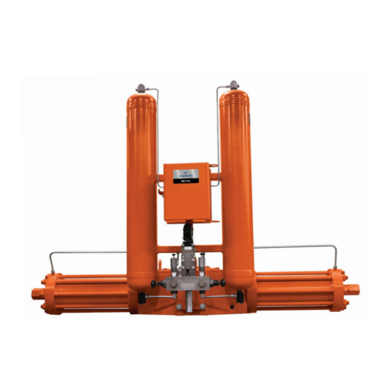
- Page 1 Installation, Operation and Maintenance Manual DOC.IOM.RG.US Rev. 11 November 2021 Bettis Rotary Gas/Hydraulic Operator Scotch Yoke Valve Operator...
- Page 2 Notes Installation, Operation and Maintenance Manual November 2021 DOC.IOM.RG.US Rev. 11 This page intentionally left blank...
-
Page 3: Table Of Contents
Installation, Operation and Maintenance Manual Table of Contents DOC.IOM.RG.US Rev. 11 November 2021 Table of Contents Section 1: Safety Warning Operating Instructions ................... 1 Installation ..................... 1 Start-Up Checks ..................... 1 Maintenance and Operational Testing ............1 End of Stroke Valve Instructions ..............1 Operator Maintenance ................... - Page 4 Table of Contents Installation, Operation and Maintenance Manual November 2021 DOC.IOM.RG.US Rev. 11 Section 10: Operator Information Operator Maintenance ................... 17 Section 11: Operator Disassembly Operator Disassembly .................... 20 Section 12: Operator Assembly Operator Assembly ....................22 Section 13: Hydraulic Fluid Hydraulic Fluid .......................
-
Page 5: Section 1: Safety Warning
Installation, Operation and Maintenance Manual Section 1: Safety Warning DOC.IOM.RG.US Rev. 11 November 2021 Section 1: Safety Warning Please refer to the applicable section for details and further information. Operating Instructions This equipment exhausts gas as part of its operating cycle. Wear hand, ear, and eye protection, and keep sparking devices and open flames away. -
Page 6: Operating Procedure
Section 1: Safety Warning Installation, Operation and Maintenance Manual November 2021 DOC.IOM.RG.US Rev. 11 Operating Procedure Manual Operation with Power Gas: Press upper left relay handle and hold to close line valve. Press upper right relay handle and hold to open line valve. To Disarm Operator: Shut off power gas supply. -
Page 7: Section 2: Operating Instructions
Installation, Operation and Maintenance Manual Section 2: Operating Instructions DOC.IOM.RG.US Rev. 11 November 2021 Section 2: Operating Instructions Refer to specific schematic drawing and list of components at the end of this document and "Operating Procedure" diagram which is located inside the control package cover on the unit. NOTE: Operating procedures for equipment with automatic switching capability vary with particular applications. - Page 8 Section 2: Operating Instructions Installation, Operation and Maintenance Manual November 2021 DOC.IOM.RG.US Rev. 11 Figure 2 Mounting instructions for valves with gear flanges Operator Operator Control Panel Cover Control Panel Cover Flange Adaptor for Matching Valve Flange Adaptor for Matching Valve (Shipped bolted to operator) (Shipped bolted to operator) Mounting...
-
Page 9: Section 3: Installation
Installation, Operation and Maintenance Manual Section 3: Installation DOC.IOM.RG.US Rev. 11 November 2021 Section 3: Installation NOTE: Mounting hardware is usually located on the shipping pallet/crate or inside panel cover of unit. Gas/Hydraulic tanks must remain generally vertical, regardless of valve and valve stem orientation. Lifting eyes are to be used in combination, with a 3 leg sling with one shortening hook, to lift the operator only. - Page 10 Section 3: Installation Installation, Operation and Maintenance Manual November 2021 DOC.IOM.RG.US Rev. 11 Figure 3 Typical lubricator extension to lubricator plug valve with rotary limit switch Yoke Cover Hub 1/4 NPT Button Head Lubricator Fitting 5/16 NC set screw 2 PLCS Yoke Cover 0.25 REF O-ring...
-
Page 11: Extended Storage
Installation, Operation and Maintenance Manual Section 3: Installation DOC.IOM.RG.US Rev. 11 November 2021 Notice the end stop adjustment table below. The stop cover must be tightened firmly to seal against full rated pressure. NOTE: If equipped, the end of stroke valve can be damaged by overtravel of the actuator. Refer to Section 9 for adjustment of end of stroke valve. -
Page 12: Section 4: Install Connections
Section 4: Install Connections Installation, Operation and Maintenance Manual November 2021 DOC.IOM.RG.US Rev. 11 Section 4: Install Connections Supply gas take-off should be from top or side of header. Supply gas connection is as per schematic drawing. User should provide a shut off valve on supply, and size lines to ensure draw down when operating valve does not interfere with pressure sensing devices, that is, use proper size of tubing for flow and pressure purposes. -
Page 13: Section 5: Prestart-Up Checks
Installation, Operation and Maintenance Manual Section 5: Prestart-Up Checks DOC.IOM.RG.US Rev. 11 November 2021 Section 5: Prestart-Up Checks Check Operator Unit has been mounted on valve properly. Gear flange mounting bolts, stem key, set screw(s) installed and secured. No tubing damaged or accessories dislodged during shipping or installation. Indicated position confirms valve position. -
Page 14: Section 6: Start-Up Checks
Section 6: Start-Up Checks Installation, Operation and Maintenance Manual November 2021 DOC.IOM.RG.US Rev. 11 Section 6: Start-Up Checks NOTE: If unit has a fail or ESD (Emergency Shut Down) position, the fail-safe or ESD controls may have to be temporarily disabled, bypassed, overridden by the control room or AUTO/MANUAL selector to avoid inadvertent valve operation. - Page 15 Installation, Operation and Maintenance Manual Section 6: Start-Up Checks DOC.IOM.RG.US Rev. 11 November 2021 Shut off power gas supply and disarm operator as per instructions. Replace any tubing that was removed or disconnected that bypassed pneumatic pilot signals for above test. Refer to schematic. Remove electrical jumper(s) installed to simulate "AUTO"...
-
Page 16: Section 7: Scheduled Maintenance And Operational Testing
Section 7: Scheduled Maintenance and Operational Testing Installation, Operation and Maintenance Manual November 2021 DOC.IOM.RG.US Rev. 11 Section 7: Scheduled Maintenance and Operational Testing A program of scheduled maintenance and operational testing of the operator by a trained technician is recommended. NOTE: De-pressurize operator before attempting to service power gas and pilot gas filter/strainer, draw contamination from the tanks, or check tank fluid level. - Page 17 Installation, Operation and Maintenance Manual Section 7: Scheduled Maintenance and Operational Testing DOC.IOM.RG.US Rev. 11 November 2021 Place both filter/strainer seals item (2) on to the ends of the reassembled outer and inner filters and insert into the manifold body item (1). Using a generous amount of grease or hydraulic fluid on the two hex cap o-rings item (6) screw the hex caps into the body until the hex cap bottoms out.
- Page 18 Section 7: Scheduled Maintenance and Operational Testing Installation, Operation and Maintenance Manual November 2021 DOC.IOM.RG.US Rev. 11 Check manual operation with power gas. Depress appropriate relay handle. There should be a steady flow of gas entering the gas/hydraulic tank. NOTE: Some effort (up to 50 lb) should be required to fully depress handle, indicating adequate supply pressure.
-
Page 19: Section 8: Instructions For The Sw-4 Limit Switch
Installation, Operation and Maintenance Manual Section 8: Instructions for the SW-4 Limit Switch DOC.IOM.RG.US Rev. 11 November 2021 Section 8: Instructions for the SW-4 Limit Switch NOTE: In hazardous locations, install sealing fitting(s) in accordance with local regulations and national code. Secure ground wire(s) to ground screw. -
Page 20: Section 9: Instructions To Set End Of Stroke
Section 9: Instruction to Set End of Stroke Installation, Operation and Maintenance Manual November 2021 DOC.IOM.RG.US Rev. 11 Section 9: Instructions to Set End of Stroke Refer to Figure 4. NOTE: Operator stops must be set for valve travel before attempting adjustments. Determine operator/valve position (open/closed position) before making adjustments. -
Page 21: Section 10: Operator Information
Installation, Operation and Maintenance Manual Section 10: Operator Information DOC.IOM.RG.US Rev. 11 November 2021 Section 10: Operator Information Refer to Figure 5 and Table 3. Table 2. Bettis Series and Model Bettis Series Bettis Model 23 SH 33 DH Series 3 43 DH 53 DH 46 DH... - Page 22 Section 10: Operator Information Installation, Operation and Maintenance Manual November 2021 DOC.IOM.RG.US Rev. 11 Table 3. Typical gas/hydraulic Parts List (Quarter-turn Operators) Item Description Material Qty. Note Drive Case Tenzaloy 713 Cover Tenzaloy 713 Yoke ASTM A148 or DI Drive Rod AISI 4140 HTSR QPQ Liquid Nitriding Drive Pin AISI 4140 Heat Treated...
- Page 23 Installation, Operation and Maintenance Manual Section 10: Operator Information DOC.IOM.RG.US Rev. 11 November 2021 NOTE: Please provide the: • MODEL identification and unit • SERIAL NO. when ordering operator repair parts (The information from gas/hydraulic tank tag will help and may suffice if no other information is obtainable.
-
Page 24: Section 11: Operator Disassembly
Section 11: Operator Disassembly Installation, Operation and Maintenance Manual November 2021 DOC.IOM.RG.US Rev. 11 Section 11: Operator Disassembly Tools and equipment required are: • For Series 3 — 1-1/2 Impact or hammer wrench — 1-1/2 Hex socket and long extension —... - Page 25 Installation, Operation and Maintenance Manual Section 11: Operator Disassembly DOC.IOM.RG.US Rev. 11 November 2021 Connect flexible hoses to the ports of the cylinder to be repaired at the tee connection. Use the handpump to cycle the operator to push the fluid out of the repair cylinder. Position the operator that the piston cap screw is against the end stop of the cylinder to be repaired.
-
Page 26: Section 12: Operator Assembly
Section 12: Operator Assembly Installation, Operation and Maintenance Manual November 2021 DOC.IOM.RG.US Rev. 11 Section 12: Operator Assembly NOTE: Gas/hydraulic tanks should be drained and flushed if fluid is contaminated with scale, rust, particulates, water, foam, or etc. Flush only with hydraulic fluid. Refill with filtered fluid. Drive case assembly Install drive rod guides and lubricate with petroleum jelly. - Page 27 Installation, Operation and Maintenance Manual Section 12: Operator Assembly DOC.IOM.RG.US Rev. 11 November 2021 Table 7. Series 3 Operator MODEL BOLT/NUT TORQUE (ft-lb) 23 SH 33 DH 43 DH 53 DH Cover bolts Cylinder plate bolts Piston nut/bolt Stay rod nuts Mounting plate bolts Note: Maximum engagement of 5/8 NC bolts into drive case is 1-3/8 inch.
-
Page 28: Section 13: Hydraulic Fluid
Section 13: Hydraulic Fluid Installation, Operation and Maintenance Manual November 2021 DOC.IOM.RG.US Rev. 11 Section 13: Hydraulic Fluid Acceptable Hydraulic Fluids • Conoco Megaflow AW HVI 22 • Conoco Megaflow AW HVI 15 • MOBIL UNIVIS HVI 13 • MOBIL UNIVIS N22 •... -
Page 29: Section 14: Troubleshooting
Installation, Operation and Maintenance Manual Section 14: Troubleshooting DOC.IOM.RG.US Rev. 11 November 2021 Section 14: Troubleshooting Of all the system components the operator itself is the least likely to malfunction and requires the most time and effort to service. For this reason, a thorough effort should be made to pinpoint the source of trouble before proceeding with operator service. -
Page 30: Section 15: Drawings And Schematics
Section 15: Drawings and Schematics Installation, Operation and Maintenance Manual November 2021 DOC.IOM.RG.US Rev. 11 Section 15: Drawings and Schematics Figure 7 Gas/Hydraulic operator with two way manual schematic SUPPLY Close Open Operation: - Shown with line valve open - Press and hold respective lever (4) to close or open line valve with power gas - Push the respective knob of selector valve on handpump to close or open with handpump... - Page 31 Installation, Operation and Maintenance Manual Section 15: Drawings and Schematics DOC.IOM.RG.US Rev. 11 November 2021 Figure 8 Typical manifold assembly and handpump for gas/hydraulic operator Exhaust, 1/2 NPTF Supply, 1/2 NPTF To operator To operator close cylinder open cylinder To close To open gas/hydraulic tank gas/hydraulic tank...
- Page 32 Section 15: Drawings and Schematics Installation, Operation and Maintenance Manual November 2021 DOC.IOM.RG.US Rev. 11 Figure 9 Model A324-M_E switching relay (3-way, 2-position) assembly drawing Note: Dimensions are in inches [mm] Table 13. Model A324-M_E switching relay (3-way, 2-position) Parts List Item Description Material...
- Page 33 Installation, Operation and Maintenance Manual Section 15: Drawings and Schematics DOC.IOM.RG.US Rev. 11 November 2021 Figure 10 Model A324-DM-275_E switching relay (3-way, 2-position, N.C.) assembly drawing Note: Dimensions are in inches [mm] Table 14. Model A324-DM-275_E switching relay (3-way, 2-position, N.C.) Parts List Item Description Material...
- Page 34 Section 15: Drawings and Schematics Installation, Operation and Maintenance Manual November 2021 DOC.IOM.RG.US Rev. 11 Figure 11 Flow control assembly - 1/4 NPTF Controlled flow inlet Free flow inlet Table 15. Flow Control Assembly - 1/4 NPTF Parts List Item Description Material Qty.
- Page 35 Installation, Operation and Maintenance Manual Section 15: Drawings and Schematics DOC.IOM.RG.US Rev. 11 November 2021 Figure 12 Flow control assembly - 1/2 NPTF Controlled flow inlet Free flow inlet Table 16. Flow Control Assembly - 1/2 NPTF Parts List Item Description Material Qty.
- Page 36 Section 15: Drawings and Schematics Installation, Operation and Maintenance Manual November 2021 DOC.IOM.RG.US Rev. 11 Figure 13 Model ES-01 assembly drawing Note: Dimensions are in inches [mm] Table 17. Model ES-01 Parts List Item Part No. Description Material Qty. Note 906-001 Upper Body AL 6061-T6...
- Page 37 Installation, Operation and Maintenance Manual Section 15: Drawings and Schematics DOC.IOM.RG.US Rev. 11 November 2021 Figure 14 Limit switch SW44 assembly drawing Access clearance 1/4 Drill thru Section A-A 3/8-16 Tap 1" Deep 4-Holes Bottom view 1/2 NPT 6 Places 1 1/2 NPT 2 Places Top view...
- Page 38 Item Description Qty. Manifold body Seal Instrument gas filter, 25 microns, SS Power gas strainer, 140 microns, SS O-ring Flush plug level seal Flush plug level seal NOTE: For Shafer Handpump drawings, please refer to MHP-01102001: www.emerson.com Drawings and Schematics...
- Page 39 Installation, Operation and Maintenance Manual Section 15: Drawings and Schematics DOC.IOM.RG.US Rev. 11 November 2021 Field Service Request To assist in providing service/assistance with your equipment, the following information is requested: Contact/Responsible Name Company Position Site/Project Identification Phone Pager Valve Operator Rotary ...
-
Page 40: Section 16: Maintenance Log
Section 16: Maintenance Log Installation, Operation and Maintenance Manual November 2021 DOC.IOM.RG.US Rev. 11 Section 16: Maintenance Log DATE TEMP, PRESSURES, POINTS CHECKED OR MAINTENANCE DONE Maintenance Log... -
Page 41: Section 17: Rotary Gas/Hydraulic Notes
Installation, Operation and Maintenance Manual Section 17: Rotary Gas/Hydraulic Notes DOC.IOM.RG.US Rev. 11 November 2021 Section 17: Rotary Gas/Hydraulic Notes Rotary Gas/Hydraulic Notes... - Page 42 Tianjin 301700 Holland Fasor 6 P. R. China Székesfehérvár 8000 The Emerson logo is a trademark and service mark of Emerson Electric Co. T +86 22 8212 3300 Hungary Bettis is a mark of one of the Emerson family of companies.
Need help?
Do you have a question about the BETTIS 23 SH and is the answer not in the manual?
Questions and answers