
Related Manuals for protech PA-6722


Summary of Contents for protech PA-6722
- Page 1 MANUAL PA-6722 15" POS Terminal Powered by Intel Celeron J1900 Quad-Cord PA-6722 M6...
- Page 2 CHAPTER INTRODUCTION This chapter gives you the information for the PA-6722. It also outlines the system specifications. Sections included: About This Manual POS System Illustration System Specifications Safety precautions Experienced users can jump to chapter 2 on page 2-1 for a quick start.
- Page 3 COPYRIGHT NOTICE & TRADEMARK All trademarks and registered trademarks mentioned herein are the property of their respective owners. This manual is copyrighted June 2014. You may not reproduce or transmit in any form or by any means, electronic, or mechanical, including photocopying and recording.
-
Page 4: About This Manual
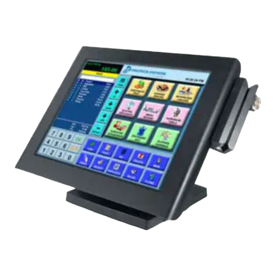
1-1. ABOUT THIS MANUAL Thank you for purchasing our PA-6722 Series System. The PA-6722 is an updated system designed to be comparable with the highest performance of IBM AT personal computers. The PA-6722 provides faster processing speed, greater expandability and can handle more tasks than before. - Page 5 Panel-PC Page.5...
- Page 6 Easy Stand Bezel-free TouchScreen Non-bazel-free 15" Touch & LCD Optional - Power MSR & iButton LED light Stand Adjustable angle 30~50 degrees Page.6...
- Page 7 Small Stand Adjustable angle 0~70 degrees Page.7...
-
Page 8: Printer Stand
PRINTER Stand Page.8... - Page 9 Caution: The correct method of "Closing Printer-Door". Please refer to below drawings. Page.9...
-
Page 10: System Specifications
1-3. SYSTEM SPECIFICATIONS System ® ® Intel Celeron J1900 Quad-Core 2.0GHz Memory 1 x DDR3 SO-DIMM 204-pin socket, up to 8GB OS Support Windows Embedded 8 Industry Pro Retail Window Embedded POSReady7 1 x Giga LAN 1 x DB-15 Wireless LAN (Optional) 802.11 b/g/n AP distance 0°... - Page 11 Power Consumption (AC): Power Supply: 60~90 Watt power adapter WORKING System ODLE status w/o Printer with Printer Burn-in Test loading Set Shut down standby 100% /CPU /HDD /MEMORY 5V x4 ports with dummy 12V x2 ports with dummy 5V x1 ports with dummy with 24V/1.2A For Printer...
- Page 12 Display 15” TFT XGA LCD Max. Resolution: 1024 x 768 Signal Interface: TTL (24-bit) Touchscreen 15” 5-wire resistive type Projected capacitive type Brightness Resistive TouchScreen Minimum 160 cd/m Projected Capacitive TouchScreen Minimum 180 cd/m Environment Temperature Operating: 0 ~ 35°C (32 ~ 95°F) Storage: -5 ~ 60°C (-27 ~ 140°F) Humidity 20~90%...
- Page 13 Optional accessories MSR & i-Button ISO I ,II, III; JIS I,II and support information key reader RFID ISO14443A, Mifare, Felica-lite Fingerprint 8-bit grayscale reader Display 8” LCD (Resolution: 800 x 600) 10.4” LCD (Resolution: 1024 x 768 or 800 x 600) Customer Display Interface: RS-232C Baud Rate: 9600/19200 bps Placement: 20 columns and 2 lines, each column is 5...
- Page 14 Printer 2” or 3” easy loading thermal printer with auto-cutter Printer: Items Specifications Printing method Thermal dot line printing Printing accuracy 1mm /5M Paper feed pitch 0.0625 mm Maximum Paper-Roll 80mm thickness Total dots per line & 2inch 432 dots; Printable dots per line 3inch 576 dots Maximum print speed...
- Page 15 Printer Auto-cutter: Items Specifications Paper cutting method Slide cutting Type of paper cutting Full cut and Partial cut (1.5 ± 0.5 mm tab left at the center) Paper curling tendency Fixed blade side and Movable blade side Minimum paper core φ8 mm (paper thickness: 75µm diameter or thin)
-
Page 16: Safety Precautions
Avoid exposure to sunlight for a long period of time (for example, in a closed car in summer time. Also avoid the system from any heating device.). Or do not use the PA-6722 when it has been left outdoors in a cold winter day. -
Page 17: System Configuration
CHAPTER SYSTEM CONFIGURATION Helpful information that describes the jumper and connector settings, component locations, and pin assignment. Sections included: External I/O Port Pin Assignment How to Set Jumpers Component Locations & Jumper Settings - Mainboard - Printer Board (peripheral device) - VFD Board (peripheral device) - MSR Board (peripheral device) Secondary Cash Drawer Port... -
Page 18: System External I/O Port & Pin Assignment
2-1. SYSTEM EXTERNAL I/O PORT & PIN ASSIGNMENT COM2 DRW1 Rear I/O COM1 2/3/4 USB1 COM3 -DIS PWR RJ45 PRINT COM4 RJ11 DRW1-1 Side I/O Power USB5 button Page.18... -
Page 19: Power Button
Power Button To turn on the system, press the power button on the side of the system briefly. ACTION ASSIGNMENT Power Click Release +3.3V Button DC-IN Port DC IN: DC Power-In Port (rear IO) ASSIGNMENT ASSIGNMENT +24V +24V DC IN VGA Port VGA: VGA Port, D-Sub 15-pin (rear IO) ASSIGNMENT... - Page 20 COM Port COM1, COM2, COM3: COM Ports (rear IO) ASSIGNMENT ASSIGNMENT DCD1/2/3 DSR1/2/3 RXD1/2/3 RTS1/2/3 TXD1/2/3 CTS1/2/3 COM 1 RI/+5V/+12V /COM 2 selectable DTR1/2/3 (Maximum /COM 3 current: 1A) /COM 4 (option) USB Port USB1, USB2, USB3, USB4, USB5: USB Type A Ports USB 1 USB 1~4: Rear I/O /USB 2...
- Page 21 LAN Port LAN: LAN RJ45 Port (rear IO) ASSIGNMENT ASSIGNMENT MDIP0 MDIP2 MDIN0 MDIN2 MDIP1 MDIP3 MDIN1 MDIN3 RA Ver. LAN LED Indicator: Left Side LED Yellow Color Blinking LAN Message Active Yellow Green No LAN Message Active Right Side LED Green Color On 10/100Mbps LAN Speed Indicator Orange Color on...
- Page 22 Printer Power Port (Optional) PRINT PWR: DC24V power supply for the stand-printer ASSIGNMENT +24V +24V PRINT POWER Cash Drawer Port DRW1 is used by default. If you need a second port, adopt the method below. ASSIGNMENT ASSIGNMENT DRW2 Sense 12V/24V (Max. current 1A) GPIO1 /DRW1 GPIO2 /DRW2 DRW1 Sense...
-
Page 23: Mainboard Component Locations & Jumper Settings
2-2. MAINBOARD COMPONENT LOCATIONS & JUMPER SETTINGS M/B: PB-6722 JP19 JP18 JP17 JP13 JP4 4 JP10 JP11 JP12 JP_COM3 JP15 JP_COM2 PB-6722 Mainboard Component Locations Page.23... -
Page 24: How To Set Jumpers
2-2-1. How to Set Jumpers You can configure your board by setting the jumpers. A jumper consists of two or three metal pins with a plastic base mounted on the card, and by using a small plastic "cap", also known as the jumper cap (with a metal contact inside), you are able to connect the pins. - Page 25 Jumper diagrams Jumper settings Page.25...
- Page 26 COM, Cash Drawer Port voltage selection COM2 / COM3 Voltage of both COM2 & COM3 ports are made to control by jumpers on board JP_COM2, JP_COM3: Pin-headers on board JUMPER JUMPER ILLUSTRATION SELECTION SETTING JP_COM2 JP_COM3 +12V JP_COM2 JP_COM3 JP_COM2 JP_COM3 COM1 / COM4 /DRW1 Voltage of external ports "COM1 &...
- Page 27 COM Connector COM1-1, COM2-1, COM3-1, COM4-1: COM Connectors ASSIGNMENT ASSIGNMENT COM1-1/ COM2-1/ RI/+5V/+12V selectable (Max. current: 1A) COM3-1/ COM4-1/ I-Button Connector I-BUT: i-Button Connector ASSIGNMENT COM2_DTR_R_I COM2_RXD_R_I I-BUT I-Button Function Selection JP10, JP11, JP12: i-Button Function Connectors SELECTION JUMPER SETTING JUMPER ILLUSTRATION COM2 JP10 /JP11 /JP12...
- Page 28 DRW1, DRW1-1, DRW1-2 DRW1 is used by default. If you need a second port, adopt either way below. Step.1 DRW1-1 (Connect DRW1 includes two groups of GPIO pins. The with Y-cable) second group is normally unused but can be DRW1 enabled by the jumper.
- Page 29 CASH DRAWER CONFIGURATION The I/O port address of the cash drawer is 2E (hex) and 2F (hex). 2E (hex) is the address port. 2F (hex) is the data port. User must first assign the address of register by writing address value into address port 2E (hex), then write/read data to/from the assigned register through data port 2F (hex).
-
Page 30: Bottom View
Notice: DRW2 Port (Only support PA-6722 selected "Printer kit") Signal from printer board (MB-1030, MB-1011(3), PDAC3100) and be controlled by command. DRW2 port on the bottom of Stand with a cable (optional). Bottom View ASSIGNMENT ASSIGNMENT +24V Drawer Open Drawer Sense... -
Page 31: Usb Connector
USB Connector USB5_1, USB6, USB7: USB 2.0 connector ASSIGNMENT 5V (Maximum current: 0.5A) USB 5_1 /USB 6 /USB 7 Note: USB6 signal is shared from "MINI-PCIE" port. USB6 could be functioned when JP13 are set 1-3, 2-4 [short]. USB7 signal is shared from "Touch Controller" USB7 could be functioned when JP8, JP9 are set 1-2 [short]. -
Page 32: Power Connector
Power Connector DC12V: DC 12Voltage Provider Connector ASSIGNMENT VCC12 DC12V VCC12 DC24V: Power for Thermal Printer Connector ASSIGNMENT VCC24 VCC24 DC24V Inverter Connector INV1: Inverter connectors ASSIGNMENT +12V +12V BRCTR INV1 LVDS_BKLTEN Page.32... -
Page 33: Touch Panel Connector
Touch Panel Connector TOUCH1: Touch panel connectors ASSIGNMENT ASSIGNMENT LR (Low Right) UR (Up Right) LL (Low Left) UL (Up Left) Probe TOUCH1 For Reserve Connector SPK2: External audio phone jack reserve connector ASSIGNMENT HD_FRONT-OUT-L HD_FRONT-OUT-R SPK2 GPIO1: 2 ports GPIO & DC5V & DC3.3V reserve connector ASSIGNMENT GPIO 1 GPIO 2... -
Page 34: Jumper Setting
Panel Resolution Selection JP5, JP6: Panel resolution control connectors JUMPER SELECTION JUMPER ILLUSTRATION SETTING JP5: 3-5, 2-4 1024 x 768 JP6: 3-5, 4-6 (24 bit) JP5: 1-3, 4-6 1024 x 768 JP6: 3-5, 4-6 (18 bit) JP5: 3-5, 4-6 800 x 600 JP6: 3-5, 4-6 (18bit) JP13: "USB6 signal support to"... -
Page 35: Msr/Card Reader Connector
MSR/Card Reader Connector PS/2_1: MSR /Card reader connectors ASSIGNMENT KB_CLK (Output) KB_CLK_C (Input) KB_DATA_C (Input) PS/2_1 KB_DATA (Output) LVDS Connector LVDS1: LVDS Connector ASSIGNMENT ASSIGNMENT LVDS_VCC LVDS_CLKA_D+ PANEL_Reverse LVDS_CLKA_D- LVDS_CLKB_D- LVDS_CLKE_D+ 19 LVDS_A2_D+ LVDS_A2_D- LVDS_B2_D- LVDS_B2_D+ LVDS_A1_D+ LVDS_A1_D- LVDS_B1_D- LVDS_B1_D+ LVDS_A0_D+ LVDS1 LVDS_B3_D+... - Page 36 Touch Panel Signal Interface Selection JP8, JP9: Control connectors for touch panel signal interface JUMPER JUMPER SELECTION SETTING ILLUSTRATION JP8: 1-2 USB7 Connector JP9: 1-2 JP8: 2-3 Interface JP9: 2-3 Page.36...
-
Page 37: Sata & Sata Power Connector
SATA & SATA Power Connector SATA1, SATA2: Serial ATA connectors ASSIGNMENT ASSIGNMENT SATA1/ SATA2/ SATA_PWR1, SATA_PWR2: Serial ATA power connectors ASSIGNMENT SATA_PWR1 SATA_PWR2 VCC12 Clear CMOS Data Selection JP3: Clear CMOS data selection SELECTION JUMPER SETTING JUMPER ILLUSTRATION Normal Open Clear CMOS* *To clear CMOS data, you must power-off the computer and set the jumper to “Clear CMOS”... -
Page 38: Mini-Pcie / M Sata Connector
Mini-PCIe / m SATA Connector SLOT1: Mini-PCIe connector, not support USB function ASSIGNMENT ASSIGNMENT WAKE# +3.3V +1.5V SLOT1 Reserved SMB_CLK Reserved PETn2 +1.5V SMB_DATA CLKREQ# PETp2 Reserved Reserved USB D- REFCLK1- Reserved USB D+ REFCLK1+ +3.3V Reserved +3.3V Reserved Reserved Reserved Reserved Reserved... -
Page 39: Printer Board Component Locations & Pin Assignment
2-3. PRINTER BOARD COMPONENT LOCATIONS & PIN ASSIGNMENT 2-3-1. Printer Board: PDAC-3100 PDAC-3100 Printer Board Component Locations Page.39... - Page 40 2-3-1-1. Power Supply Connector CN1: Power supply wafer ASSIGNMENT +24V +24V 2-3-1-2. RS-232 Interface Connector CN7: RS-232 interface connector ASSIGNMENT ASSIGNMENT Page.40...
-
Page 41: Auto-Cutter Connector
2-3-1-3. Auto-Cutter Connector CN3: Auto-cutter wafer ASSIGNMENT FUNCTION Unused Power supply of the home position sensor GND of the home position sensor CUTS Signal of the hom position sensor 2B-1 Auto-cutter motor drive signal 2B-2 Auto-cutter motor drive signal 2A-1 Auto-cutter motor drive signal 2A-2 Auto-cutter motor drive signal... -
Page 42: Thermal Head/Motor/Sensor Connector
2-3-1-5. Thermal Head/Motor/Sensor Connector CN2: Thermal head/motor/sensor connector ASSIGNMENT FUNCTION Head drive power Head drive power Head drive power Head drive power Head drive power Head drive power Print data output Synchronizing signal for print data transfer Head GND Head GND Head GND Head GND Head GND... - Page 43 ASSIGNMENT FUNCTION Head GND LATCH Print data latch Head drive power Head drive power Head drive power Head drive power Head drive power Head drive power Unused Signal of the out-of-paper sensor Power supply of the out-of- paper sensor GND of the platen position/ out-of-paper sensor Signal of the platen position sensor...
-
Page 44: Terminal Assignment Connector
2-3-1-6. Terminal Assignment Connector CN5: Terminal assignment connector ASSIGNMENT FUNCTION FEED Feed signal RESET Reset signal Status signal Status signal Status signal Status signal Drawer sensor signal Drawer switch signal Drive terminal for the drawer (Vp side) GNDdu Drive terminal for the drawer (GND side) Unused Page.44... -
Page 45: Printer Board: Mb-1030 Series
2-3-2. Printer Board: MB-1030 series CUT_CN1 COM1 9 10 USB_CN1 24V_CN1 PRINT_CN1 MB-1030 Printer Board Component Locations Page.45... - Page 46 2-3-2-1. Power Supply Connector 24V_CN1: Power Supply Wafer ASSIGNMENT +24V +24V 24V_CN1 2-3-2-2. RS-232 Interface Connector COM1: RS-232 Interface Connector ASSIGNMENT ASSIGNMENT DSR /CTS 9 10 DTR /RTS COM1 Page.46...
- Page 47 2-3-2-3. Thermal Head/Motor/Sensor Connector PRINT_CN1: Thermal head/motor/sensor connector ASSIGNMENT FUNCTION Head drive power Head drive power Head drive power Head drive power Head drive power Head drive power Print data output Synchronizing signal for print data transfer Head GND PRINT_CN1 Head GND Head GND Head GND...
- Page 48 ASSIGNMENT FUNCTION Head GND LATCH Print data latch Head drive power Head drive power Head drive power Head drive power Head drive power Head drive power Unused Signal of the out-of-paper sensor Power supply of the out-of- paper sensor GND of the platen position/ out-of-paper sensor Signal of the platen position sensor...
- Page 49 2-3-2-4. Auto-Cutter Connector CUT_CN1: Auto-cutter Connector ASSIGNMENT FUNCTION Unused Power supply of the home position sensor GND of the home position sensor CUT_CN1 CUTS Signal of the hom position sensor 2B-1 Autocutter motor drive signal 2B-2 Autocutter motor drive signal 2A-1 Autocutter motor drive signal 2A-2...
- Page 50 2-3-2-6. USB Interface Connector USB_CN1: USB interface connector ASSIGNMENT ASSIGNMENT Vbus USB_CN1 2-3-2-7. Terminal Assignment Connector CN1: Terminal assignment connector ASSIGNMENT FUNCTION FEED Feed signal RESET Reset signal Status signal Status signal Status signal Status signal Drawer sensor signal Drawer switch signal Drive terminal for the drawer (Vp side) GNDdu...
- Page 51 2-3-3. Printer Board: MB-1011 & MB-1013 MB-1013 MB-1011 MB-1011 & MB-1013 Printer Board Component Locations Page.51...
- Page 52 2-3-3-1. Power Supply Connector CN1: Power supply wafer ASSIGNMENT +24V +24V 2-3-3-2. RS-232 Interface Connector CN7: RS-232 interface connector ASSIGNMENT ASSIGNMENT 2-3-3-4. Auto-Cutter Connector CN3: Auto-cutter Connector ASSIGNMENT FUNCTION Unused Power supply of the home position sensor GND of the home position sensor CUTS Signal of the hom position sensor 2B-1...
- Page 53 2-3-3-3. Thermal Head/Motor/Sensor Connector CN2: Thermal head/motor/sensor connector ASSIGNMENT FUNCTION Head drive power Head drive power Head drive power Head drive power Head drive power Head drive power Print data output Synchronizing signal for print data transfer Head GND Head GND Head GND Head GND Head GND...
- Page 54 ASSIGNMENT FUNCTION Head GND LATCH Print data latch Head drive power Head drive power Head drive power Head drive power Head drive power Head drive power Unused Signal of the out-of-paper sensor Power supply of the out-of- paper sensor GND of the platen position/ out-of-paper sensor Signal of the platen position sensor...
-
Page 55: Usb Interface Connector
2-3-3-6. Terminal Assignment Connector CN5: Terminal assignment connector ASSIGNMENT FUNCTION FEED Feed signal RESET Reset signal Status signal Status signal Status signal Status signal Drawer sensor signal Drawer switch signal Drive terminal for the drawer (Vp side) GNDdu Drive terminal for the drawer (GND side) Unused 2-3-3-5. -
Page 56: Vfd Board Component Locations & Pin Assignment
2-4. VFD BOARD COMPONENT LOCATIONS & PIN ASSIGNMENT 2-4-1. VFD Board: MB-4103, LD720 JP12V MB-4103 & LD720 VFD Board Component Locations 2-4-1-1. Power Switch Selection JP12V: Power Switch Selection SELECTION JUMPER SETTING JUMPER ILLUSTRATION JP12V JP12V 2-4-1-2. RS-232 Serial Interface Connector CN1: RS-232 serial interface wafer ASSIGNMENT ASSIGNMENT... -
Page 57: Msr Board Component Locations & Pin Assign- Ment
2-5. MSR BOARD COMPONENT LOCATIONS & PIN ASSIGN- MENT 2-5-1. ID TECH ID-TECH MSR Board Component Locations 2-5-1-1. Main Connector ASSIGNMENT ASSIGNMENT Chassis Ground K-CLK (Computer connections) P-CLK K-DATA (Keyboard connections) (Computer connections) P-DATA (Keyboard connections) +5V Vcc Page.57... - Page 58 2-5-3. MB-3012 I_BUTTON1 MB-3012 MSR Board Component Locations 2-5-3-1. Information Button Reader I_BUTTON1: Information button reader ASSIGNMENT I_B1 I-BUTTON1 2-5-3-2. Output Connector IO1: Output wafer ASSIGNMENT ASSIGNMENT CLK_KB RX_MSR CLK_PC TX_MSR DATA_KB DATA_PC USB_D+_R USB_D-_R CHASSIS GND Page.58...
- Page 59 CHAPTER SOFTWARE This chapter provides the detailed information of driver utilities and BIOS settings for the system. Sections included: Driver ® - Intel Chipset Software Installation Utility - VGA Driver Utility - LAN Driver Utility - Sound Driver Utility - Touchsreen Driver Utility - Fingerprinter Driver Utility (Optional) - RFID Module Driver (Optional) - Wireless Module Driver (Optional)
- Page 60 3-1. DRIVER DISC 3-1-1. Introduction Enclosed with the PA-6722 Series package is our driver utilities, which comes in a CD-ROM format. 3-1-2-1. API Package folder Refer to the "3-3 API" for the details. +--->\DEMO PROJECT\ +--->\ProxAPI standard\ +--->\Document\ 3-1-2-2. DRIVER folder 1.
-
Page 61: Intel Chipset Software Installation Utility
OS installation. Please follow the steps below: Connect the USB CD-ROM device to PA-6722 and insert the driver disk. Enter the “Main Chip” folder where the Chipset driver is located (depending on your OS platform). -
Page 62: Vga Driver Utility
3-1-4. VGA Driver Utility The VGA interface embedded with PA-6225 can support a wide range of display types. You can have dual displays via CRT & LVDS interfaces work simultaneously. 3-1-4-1. Installation of VGA Driver To install the Graphics driver, follow the steps below: Connect the USB-CD ROM device to PA-6225 and insert the driver disk. -
Page 63: Sound Driver Utility
3-1-6. Sound Driver Utility The sound function enhanced in this system is fully compatible with Windows POSReady 7 & Embedded 8 Industry series. Below, you will find the content of the Sound driver. 3-1-6-1. Installation of Sound Driver To install the Sound Driver, follow the steps below: Connect the USB CD-ROM device to PA-6225 and insert the driver disk. -
Page 64: Fingerprinter Driver Utility (Optional)
Click Setup.exe file for driver installation. Follow the on-screen instructions to complete the installation. Once installation is completed, shut down the system and restart PA-6722 for the changes to take effect. 3-1-9. RFID Module Driver Utility (Optional) The RFID driver utility can only be installed on Windows POSReady7 &... -
Page 65: Wireless Module Driver Utility (Optional)
3-1-10. Wireless Module Driver Utility (Optional) The wireless driver utility can only be installed on Windows POSReady7 & Embedded 8 Industry series, and it should be installed right after the OS installation. 3-1-10-1. Installation of Wireless Driver To install the wireless driver, follow the steps below: Connect the USB CD-ROM device to PA6722 and insert the driver disk. -
Page 66: Standard Commands
2. Command List Standard commands Command Command Command ESC D GS / ESC E GS : ESC G GS B ESC J GS H ESC L GS I DLE EOT ESC M GS L DLE ENQ ESC c 4 GS P DLE DC4 ESC c 5 GS V... -
Page 67: Command List
COMMAND LIST Standard Commands Hexadec Stand Control Page -imal Function -ard Codes Mode Codes Mode <HT> Horizontal tab <LF> Print and line feed Print and recover to standard mode <FF> Ignored (in page mode) <CR> Print and carriage return <CAN> Cancel print data in page mode Ignored <DLE EOT>... - Page 68 <ESC {> 1B 7B Turn upside-down printing mode on/off ▲ ◎ <FS p> 1C 70 Print NV bit image Disabled <FS q> 1C 71 Define NV bit image Disabled ◎ <GS !> 1D 21 Select character size Set absolute vertical print position in <GS $>...
-
Page 69: Command Details
Kanji Control Commands (when the Japanese, Simplified Chinese, Traditional Chinese, or Korean model is used) Hexadec Stand Control Page -imal Function -ard Codes Mode Codes Mode <FS !> 1C 21 Set print mode(s) for Kanji characters <FS &> 1C 26 Select Kanji character mode Turn underline... - Page 70 [Name] Print and line feed ASCII [Format] Hex. Decimal 10 [Range] Prints the data in the print buffer and performs a line feed based on the set line [Description] feed amount. After execution, makes the top of the line the next print starting position. [Name] Print and recover to standard mode (in page mode) ASCII...
- Page 71 DLE EOT n [Name] Real-time status transmission. ASCII OLE EOT n [Format] Hex. Decimal [Range] 1 ≤ n ≤ 4 Transmits the selected printer status specified by n in real time, according to the following parameters: n = 1 : Transmit printer status. n = 2 : Transmit off-line status. n = 3 : Transmit error status.
- Page 72 On / Off Decimal Function Not used. Fixed to Off. Not used. Fixed to On. No paper-near-end stop. Printing stops due to paper near end. No paper-near-end stop. Printing stops due to paper near end. Not used. Fixed to On. No paper-end stop.
- Page 73 ESC FF [Name] Print data in page mode. ASCII ESC FF [Format] Hex. Decimal [Range] Prints all buffered data in the print area collectively in page mode. This command is enabled only in page mode. Holds the following information after printing. [Description] a.
- Page 74 ESC $ nL nH [Name] Set absolute print position. ASCII ESC $ nL nH [Format] Hex. 1B 24 nL nH Decimal 27 36 nL nH [Range] 0 ≤ (nL + nH x 256) ≤ 65535 (0 ≤ nH ≤ 255, 0 ≤ nL ≤ 255) This command specifies the next print starting position in reference to the left edge of the print area.
- Page 75 ESC 2 [Name] Select default line spacing. ASCII ESC 2 [Format] Hex. 1B 32 Decimal 27 50 [Range] This command sets the default line spacing The default line spacing is approximately [Description] 4.25 mm, which is equivalent to 34 dots. ESC 3 n [Name] Set line spacing.
- Page 76 ESC D n1…nk NUL [Name] Set horizontal tab position ASCII n1...nk NUL [Format] Hex. n1...nk NUL Decimal 27 n1...nk NUL 1 ≤ n ≤ 255 [Range] 0 ≤ k ≤ 32 Sets horizontal tab position n specifies the column number for setting a horizontal tab position from the left [Description] margin or the beginning of the line.
- Page 77 In standard mode, the printer uses the vertical motion unit (y). In page mode, this command functions as follows, depending on the starting position of the printable area: (1) When the starting position is set to the upper left or lower right of the printable area using ESC T, the vertical motion unit (y) is used.
- Page 78 ESC M n [Name] Select character font. ASCII ESC M n [Format] Hex. 1B 4D n Decimal 27 77 n n = 0, 1 [Range] Initial Value n = 0 This command selects ANK character fonts using n as following. Function [Description] Character font A selected...
- Page 79 ESC S [Name] Select standard mode ASCII ESC S [Format] Hex. 1B 53 Decimal 27 83 [Range] Valid only when input by page mode. All buffer data in page mode is deleted. Sets the print position to the beginning of the next line after execution. The print area set by ESC W (Set print region in page mode) is reset to the default setting.
- Page 80 ESC V n [Name] Turn 90 degree clockwise rotation mode on/off ASCII ESC V n [Format] Hex. 1B 56 n Decimal 27 86 n 0 ≤ n≤ 1, 48≤ n ≤49 [Range] Initial Value n = 0 Specifies or cancels character 90 degree clockwise rotation. Function 0, 48 Turns off 90 degree clockwise rotation mode...
- Page 81 ESC \ nL nH [Name] Set relative print position. ASCII ESC \ nL nH [Format] Hex. 1B 5C nL nH Decimal 27 92 nL nH [Range] 0 ≤ (nL + nH x 256) ≤ 65535 (0 ≤ nL 255, 0 ≤ nH ≤ 255) Specifies the next print starting position with a relative position based on the current position.
- Page 82 ESC c 4 n [Name] Select paper sensor(s) to stop printing. ASCII ESC c [Format] Hex. 63 34 n Decimal 99 52 n Specification: 0 ≤ n ≤ 3 [Range] Initial Value n = 0 Selects the paper out detector to stop printing when paper has run out. Function 〝...
- Page 83 ESC m [Name] Partial cut. ASCII ESC m [Format] Hex. Decimal 27 [Range] This command executes a partial cut of the paper with one point uncut in standard [Description] mode. ESC p m t1 t2 [Name] General pulse. ASCII ESC p m t1 t2 [Format] Hex.
- Page 84 ESC { n [Name] Turns upside-down printing mode on/off. ASCII ESC { [Format] Hex. 7B n Decimal 27 123 n 0 ≤ n ≤ 255 [Range] Initial Value n = 0 Specifies or cancels upside-down printing. Cancels upside-down printing when n = <*******0>H. Specifies upside-down printing when n = <*******1>H.
- Page 85 Defines the specified NV bit image. n specifies the number of NV bit images to define. xL and xH specify the horizontal direction for one NV bit image (xL + xH x 256) x 8 dots. yL and yH specify the vertical direction for one NV bit image (yL + yH x 256) x 8 dots.
- Page 86 Table 1 [Enlarged in horizontal direction] Decimal Enlargement 1 time(standard) 2 times 3 times 4 times 5 times 6 times 7 times 8 times Table 2 [Enlarged in vertical direction] Decimal Enlargement 1 time(standard) 2 times 3 times 4 times 5 times 6 times 7 times...
- Page 87 Defines the download bit image of the number of dots specified by X and Y. X specifies the number of bytes in the horizontal direction. Y specifies the number of bytes in the vertical direction. Horizontal direction dot count is X x 8 dots; Vertical direction dot count is Y x 8 dots d indicates the bit-image data.
- Page 88 GS ( K pL pH n m [Name] Set print density. [Format] ASCII GS ( A pL pH n m Hex. 1D 28 4B pL pH n m Decimal 29 40 75 pL pH n m [Range] {pL+ (pH×256) } = 2 (pL = 2,pH = 0) n = 49 250 ≤...
- Page 89 GS B n [Name] Turn white/black reverse printing mode on/off ASCII GS B n [Format] Hex. 1D 42 n Decimal 29 66 n 0 ≤ n ≤ 255 [Range] Initial Value n = 0 Specifies or cancels black and white inverted printing. Cancels black and white inverted printing when n = <*******0>B.
- Page 90 GS L nL nH [Name] Set left margin. ASCII GS L nL nH [Format] Hex. 1D 4C nL nH Decimal 29 76 nL nH 0 ≤ nL ≤ 255, 0 ≤ nH ≤ 255 [Range] Initial Value (nL + nH x 256)=0 (nL=0, nH=0) nL and nH set the specified left margin.
- Page 91 GS W nL nH [Name] Set printing area width. ASCII GS W nL nH [Format] Hex. 1D 57 nL nH Decimal 29 87 nL nH [Range] 0 ≤ nL ≤ 255, 0 ≤ nH ≤ 255 Sets the print region width specified by nL and nH. Print region width is [(nL + nH x 256) x basic calculated pitch].
- Page 92 The printer information transmitted is comprised of 4 bytes as follows: First byte(printer information) Off/On Hex Decimal Function Not used. Fixed to Off Paper is not being fed by the paper feed button Paper is being fed by the paper feed button Cover is close Cover is open Not used.
- Page 93 GS f n [Name] Select font for HRI characters. ASCII [Format] Hex. 1D 66 n Decimal 29 102 n n = 0,1,48,49 [Range] Initial Value n = 0 Selects the HRI character font when printing bar codes. Font [Description] 0, 48 Selects Font A (12 x 24).
- Page 94 Bar Code Type Defined region of n Defined region of d UPC-A 11 ≤ n ≤ 12 48 ≤ d ≤ 57 UPC-E 11 ≤ n ≤ 12 48 ≤ d ≤ 57 JAN13 (EAN13) 12 ≤ n ≤ 13 48 ≤...
- Page 95 GS v 0 m xL xH yL yH d1 … dk [Name] Print raster bit image. ASCII m xL xH yL yH d1...dk m xL xH yL yH d1...dk [Format] Hex. Hex. 1D 76 30 m xL xH yL yH d1...dk 1D 76 30 m xL xH yL yH d1...dk Decimal 29 118 48 m xL xH yL yH d1...dk Decimal 29 118 48 m xL xH yL yH d1...dk...
- Page 96 Sets the bar code horizontal size. Multi-level Bar Code Binary Level Bar Code Module Width [mm] Fine Element Width[mm] Thick Element Width[mm] 0.141 0.141 0.423 [Description] 0.282 0.282 0.706 0.423 0.423 1.129 0.564 0.564 1.411 0.706 0.706 1.834 0.847 0.847 2.258 TWO-DIMENSIONAL BAR CODE COMMAND DETAILS DC2 ;...
- Page 97 Prints QRCode data based on the specified contents. model: Specifies a model e: Selects an error correction level. ’L’ (4CH), ’M’ (4DH), ’Q’ (51H), ’H’ (48H) v: =0: Automatic selection (A version is automatically selected depending on the number of input data.)1 ≤ v ≤...
- Page 98 FS - n [Name] Turn underline mode on/off for Kanji characters ASCII [Format] Hex. 1C 2D Decimal 28 45 [Range] 0 ≤ n ≤ 2, 48 ≤ n ≤ 50 Specifies or cancels Kanji character underlines. Function 0,48 Cancels Kanji character underline [Description] 1,49 Sets to one-dot width Kanji character underline and...
- Page 99 This setup also installs the MB1030 program. Follow the wizard instructions to complete the installation. Launching Program Below steps guide you to load the MB1030 program. Click POSPrinter folder from the path Start\Programs\Protech OPOS. Click MB1030 to launch the program. Page.99...
- Page 100 OPOS Control Object of MB1030 Program a.) Print tab buttons: Button/Item Description Printer Normal Print the string. b.) Bitmap tab buttons/items: Button/Item Description Load Load bitmap file. Print Bitmap Print bitmap file. Type Normal or Rotate 108°. Page.100...
- Page 101 c.) BarCode tab buttons/items: Button/Item Description Print BarCode Print the barcode. Supported barcode types: UPCA, UPCE, EAN8, EAN13, ITF, Codabar, Code39, Code93, Code128 Alignment Left, center or right Position Print barcode number (None, Above or Below) MB1030 type Key Name Type Default Value Note...
- Page 102 OPOS APIs Support List Category Name Mutability OPOS Printer .SO Type Version Properties common bool AutoDisable Not Applicable Properties common long BinaryConversion Not Applicable Properties common long CapPowerReporting Read only Not Applicable Properties common CheckHealthText Read only Supported string Properties common bool Claimed Read only Supported Properties common long DataCount...
- Page 103 Category Name Mutability OPOS Printer .SO Type Version Properties specific long CapJrnCartridgeSensor Read only Not Applicable Properties specific long CapJrnColor Read only Not Applicable Properties specific long CapJrnDhigh Read only Not Applicable Properties specific long CapJrnDwide Read only Not Applicable Properties specific long CapJrnDwideDhigh Read only...
- Page 104 Category Name Mutability OPOS Printer .SO Type Version Properties specific long CapSlpCartridgeSensor Read only Not Applicable Properties specific long CapSlpColor Read only Not Applicable Properties specific bool CapSlpDhigh Read only Not Applicable Properties specific bool CapSlpDwide Read only Not Applicable Properties specific bool CapSlpDwideDhigh Read only...
- Page 105 Category Name Mutability OPOS Printer .SO Type Version Properties specific long RecLineHeight Not Applicable Properties specific long RecLineSpacing Not Applicable Properties specific long RecLineWidth Read only Not Applicable Properties specific bool RecLetterQuality Not Applicable Properties specific bool RecEmpty Read only Not Applicable Properties specific bool RecNearEnd...
- Page 106 Category Name Mutability OPOS Printer .SO Type Version Methods common ClearOutput Not Applicable Methods common DirectIO Not Applicable Methods specific PrintNormal Supported Methods specific PrintTwoNormal Not Applicable Methods specific PrintImmediate Not Applicable Methods specific BeginInsertion Not Applicable Methods specific EndInsertion Not Applicable Methods specific...
- Page 107 3-2-2. VFD: MB-4103 (RS-232) 3-2-2-1. Command List VFD Registry Operation Registry Path: [HKEY_LOCAL_MACHINE\SOFTWARE\OLEforRetail\ServiceOPOS\ LineDisplay\Prox-PMP4000] Registry Name Default Data Notes Default Value LineDisplay.PMP4000.1 BaudRate 9600 BitLength Parity Port COM1 Stop OPOS VFD Service Object and Method Relations Method Status of support Notes Open ○...
- Page 108 This setup also installs the Prox-PMP4000 program. Follow the wizard instructions to complete the installation. Launching Program Below steps guide you to load the Prox-PMP4000 program. Click LineDisplay folder from the path Start/Programs/Protech OPOS. Click Prox-PMP4000 to launch the program. Page.108...
- Page 109 OPOS Control Object of Prox-PMP4000 program Main screen buttons: Button/Item Description Text Display text at the current cursor position. TextAt Display the string of characters at the specified “y ” and “x ”. Clear Clear the current window by displaying Attribute Normal, blink, reverse, blink, reverse MB4103 type...
- Page 110 OPOS APIs Support List Category Name Mutability OPOS VFD .SO Type Version Properties common bool AutoDisable Not Applicable Properties common long BinaryConversion Not Applicable Properties common long CapPowerReporting Read only Not Applicable Properties common CheckHealthText Read only Supported string Properties common bool Claimed Read only Supported Properties common long DataCount...
- Page 111 Category Name Mutability OPOS VFD .SO Type Version Properties specific bool CapICharWait Read only Not Applicable Properties specific long CapReadBack Read only Not Applicable Properties specific long CapReverse Read only Not Applicable Properties specific bool CapVMarquee Read only Not Applicable Properties specific long BlinkRate Not Applicable...
- Page 112 Category Name Mutability OPOS VFD .SO Type Version Methods common DirectIO Not Applicable Methods specific DisplayText Supported Methods specific DisplayTextAt Supported Methods specific ClearText Supported Methods specific ScrollText Not Applicable Methods specific SetDescriptor Not Applicable Methods specific ClearDescriptors Not Applicable Methods specific CreateWindow...
- Page 113 This setup also installs the Prox-PMP3000 program. Follow the wizard instructions to complete the installation. Launching Program Below steps guide you load the Prox-PMP3000 program. Click MSR folder from the path Start/Programs/Protech OPOS. Click Prox-PMP3000 to launch the program. Page.113...
- Page 114 Configuration of Prox-PMP3000 program a.) Main screen & Control tab items: Button/Item Description (dropdown list) To set COM port number (only for USRT/USB interface). AutoDisable (check box) Set auto-disable FreeseEvents (check box) Set freeze events Page.114...
- Page 115 b.) Description tab: S.O and C.O information c.) Track Control tab items Button/Item Description DecodeData Set decode data properties applicable). ParseDecodeData Set parse decode data properties TransmitSentinels Set transmit-sentinels properties ErrorReporting Type Card, track TracksToRead Track1, track2, track3, tracks12, tracks13, tracks14, tracks23, tracks24, tracks34, tracks123, tracks124, tracks134, tracks234, tracks1234 (Tracks4 is not applicable).
- Page 116 d.) Track Data tab items Button/Item Description TracksData (Row) Display data of all tracks (Track4 is not applicable). e.) Parsed Data tab items Button/Item Description Parsed Data Display special properties. Page.116...
- Page 117 MB301X type (RS232/PS2) Key Name Type Default Value Note default string PMP3000 OPOS S.O Link OPOS APIs support List Category Name Mutability OPOS VFD .SO Type Version Properties common bool AutoDisable Supported Properties common long BinaryConversion Not Applicable Properties common long CapPowerReporting Read only Supported Properties common...
- Page 118 Category Name Mutability OPOS VFD .SO Type Version Properties specific long TracksToRead Supported Properties specific bool DecodeData Not Applicable Properties specific bool ParseDecodeData Supported Properties specific long ErrorReportType Not Applicable Properties s pecific string Track1Data Read only Supported Properties s pecific string Track2Data Read only Supported Properties s pecific string Track3Data...
- Page 119 3-2-4. MSR: GIGA-TMS MJR243R (RS-232) 3-2-4-1. Command List MSR Registry Operation Registry Path: [HKEY_LOCAL_MACHINE\SOFTWARE\OLEforRetail\ServiceOPOS\ MSR\MJR243] Registry Name Default Data Notes CapISO Capability for reading ISO track data CapJISOne (reserved) CapJISTwo (reserved) CapTransmitSentinels Capability for reading Transmit Sentinels Debug Enable the tracing, and create a log file Description GIGATMS...
- Page 120 OPOS MSR Service Object and Method Relations Method Status of support by Notes the driver Open ○ Close ○ Claim ○ ClaimDevice ○ Release ○ ReleaseDevice ○ ClearInput ○ ClearInputProperties ○ DataEvent ○ Claimed Read only ○ DataCount Read only ○...
- Page 121 Method Status of support by Notes the driver ServiceCode Read Only ○ Suffix Read Only ○ Surname Read Only ○ Title Read Only ○ Track1Data Read Only ○ Track1DiscretionaryData Read Only ○ Track2Data Read Only ○ Track2DiscretionaryData Read Only ○ Track3Data Read Only ○...
-
Page 122: Opos Msr Register
3-2-4-2. OPOS MSR Register The OPOS MSR Register program sets up the registry information of MSRHK reader for OPOS program uses. Installation Below steps guide you to install the OPOS MSR Register program. Insert the setup CD Run the setup file OPOSMSR_Setup.exe located in the Software folder of CD. This setup also installs the OPOS MSR Tester program. - Page 123 Configuration of OPOS MSR Register program a.) Main screen buttons/items: Button/Item Description Control Object (Check box) Register the OPOSMSR.ocx common control object driver. This needs to be checked to run the OPOS MSR Tester program. Service Object (Left pane) The Service Object driver types. So far only four types are supported.
- Page 124 c.) Example 1. MAGTEK USB HID d.) Example 2. PROMAG MSR/MJR PART NO, Keyboard mode. ‐ Page.124...
- Page 125 e.) Example 3. PROGRAM MSR PART NO, HID mode. ‐ If your system doesn’t have any other common control driver, then click Control Object check box. Note: To run the OPOPS MSR Tester program, the Control Object must be checked. MJR243 type Key Name Type...
- Page 126 Key Name Type Default Value Note HardwareProvider string (reserved) Model string MJR243 Device model name Parity string None Parity for the communication port Port string COM4 Comport Number Protocol string Hardware Communication Control Baudrate string 19200 RS232 baudrate OPOS APIs support list Category Name Mutability OPOS...
- Page 127 Category Name Mutability OPOS MSR .SO Type Version string Description Properties common long ServiceObjectVersion Read only Supported Properties common DeviceDescription Read only Supported string Properties common DeviceName Read only Supported string Properties specific bool CapISO Read only Supported Properties specific bool CapJISOne Read only Not Applicable...
- Page 128 Category Name Mutability OPOS MSR .SO Type Version Properties specific long TracksToWrite Not Applicable Properties specific bool TransmitSentinels Supported Methods common Open Supported Methods common Close Supported Methods common Claim Supported Methods common ClaimDevice Supported Methods common Release Supported Methods common ReleaseDevice Supported...
-
Page 129: Opos Msr Tester
3-2-4-3. OPOS MSR Tester The OPOS MSR Tester program is used to get the track data of MSRHK reader via the OPOS driver. Before running the program, make sure the device name registry information for MSRHK reader has been already created by OPOS MSR Register program. - Page 130 Configuration for OPOS MSR Tester Program a.) Main screen buttons/items: Button/Item Description Device Name (Combo box) Enter the device name that to be loaded to the program. Track Data (Text boxes) Show the raw and parsed track data. Clear (Button) Clear all the track data in the text boxes. Open: (Button) Open the OPOS driver and ready to get track data.
- Page 131 c.) Example 1. MAGTEK USB HID. d.) Example 2. PROMAG MSR/MJR PART NO, Keyboard mode ‐ Page.131...
- Page 132 e.) Example 3. PROMAG MSR PART NO, HID mode ‐ Page.132...
- Page 133 3-3 API API Package Content Users can find the enclosed API Package files inside the Protech Manual / Driver CD. Depending on machine types, the API Package files may include the following: Function DLL Directory Function File Name Description Cash Drawer Cash Drawer.dll...
- Page 134 API Procedure Take VB2005 .NET for example, first you must declare a function. You may create a module in your project and fill in the function, cash drawer for example. Declare Function GetCashDrawerStatus Lib CashDrawer.dll (ByVal num_drawer as short) As Boolean Declare Function CashDrawerOpen Lib CashDrawer.dll (ByVal num_drawer as short) As Boolean Next, create a button to call API Function...
- Page 135 Sample Code (1) VB Declaration Declare Function GetCashDrawerStatus Lib CashDrawer.dll (ByVal num_drawer as short) As Boolean Declare Function CashDrawerOpen Lib CashDrawer.dll (ByVal num_drawer as short) As Boolean (2) Call Function Open cash drawer: CashDrawerOpen(1) Open cash drawer1 CashDrawerOpen(2) Open cash drawer2 Check cash drawer status: Dim receive_status as Boolean Check cash drawer1 status...
- Page 136 Bool bstatus; bstatus = PortAccess.GetCashDrawerStatus(0x01); bstatus = PortAccess.GetCashDrawerStatus(0x02); //Before get cash drawer status, need to initial cash drawer first VB.NET extern function: Declare Function SetMinSec Lib “WatchDog.dll” (ByVal kind As Short,ByVal delay_time As Short) As Boolean Declare Function Stopwatchdog Lib “WatchDog.dll” ( ) As Short Declare Function Setwatchdog Lib “WatchDog.dll”...
-
Page 137: Cash Drawer
Cash Drawer [OPEN] Tap to open the cash drawer. Cash Drawer Status Cash drawer status will be displayed after [OPEN] is tapped. Cash drawer is closed as shown. Cash drawer is open as shown. Page.137... - Page 138 Watch Dog Count Mode Select the unit of time, second or minute, for the watchdog timer. Setting Time Set Timeout Set the timeout for the watchdog. The maximum timeout value is 255 seconds or minutes. Watch Dog Control Timeout Value Simulation timer of the API program, the running watchdog timeout will be displayed (in seconds).
- Page 139 API Function The API program-related sample programs, developed in VB.Net and C#, are provided for easy use of the API Package. Refer to the main API functions listed as below. API Function Cash CashDrawerOpen CashDrawer.dll Drawer GetCashDrawerStatus Watchdog_Set Watchdog Watchdog_Stop multilangXML WatchDog.dll (WD)
- Page 140 if (data) MsgBox(“open1”); // Cash Drawer1 status “Open” Else MsgBox(“close1”); // Cash Drawer1 status “Close” Endif Watch Dog Function Watchdog_Set bool Watchdog_Set (int value) Purpose Set the timeout for the watchdog timer. Value value = 0 ~ 255 Return True (1) on success, False (0) on failure Watchdog_SetMinSec bool Watchdog_SetMinSec (int kind) Purpose...
-
Page 141: Operation Guide
3-4-1 Operation Guide Introduction The board PA-6722 uses an AMI Aptio BIOS that is stored in the Serial Peripheral Interface Flash Memory (SPI Flash) and can be updated. The SPI Flash contains the BIOS Setup program, Power-on Self-Test (POST), the PCI auto-configuration utility, LAN EEPROM information, and Plug and Play support. - Page 142 The BIOS Setup program can be used to view and change the BIOS settings for the computer. The BIOS Setup program is accessed by pressing the <Del> or <ESC> key after the POST memory test begins and before the operating system boot begins.
- Page 143 Setup program initial screen You may move the cursor by up/down keys to highlight the individual menu items. As you highlight each item, a brief description of the highlighted selection will appear at the bottom of the screen. Page.143...
-
Page 144: Main Screen
Main Main Screen BIOS Setting Options Description/Purpose BIOS Vendor No changeable options Displays the BIOS vendor. Core Version No changeable options Displays the current BIOS core version. Compliancy No changeable options Displays the current UEFI version. Displays the version of the BIOS Project Version No changeable options currently installed on the platform. - Page 145 Advance Advanced Screen BIOS Setting Options Description/Purpose ACPI Settings Sub-Menu System ACPI Parameters. F81866 Super IO Configuration Sub-Menu System Super IO Chip Parameters Hardware Monitor Sub-Menu Monitor hardware status F81866 Watchdog Sub-Menu F81866 Watchdog Parameters. CPU Configuration Sub-Menu CPU Configuration. Parameters. IDE Configuration Sub-Menu SATA Configuration Parameters.
- Page 146 ACPI Settings ACPI Settings Screen BIOS Setting Options Description/Purpose Enables or Disables System ability to Hibernate - Disabled Enable Hibernation (OS/S4 Sleep State). This option may be not - Enabled effective with some OS. Page.146...
- Page 147 F81866 Super IO Configuration F81866 Super IO Configuration Screen BIOS Setting Options Description/Purpose Set Parameters of Serial Port 1 Serial Port 1 Configuration Sub-menu (COMA) Set Parameters of Serial Port 2 Serial Port 2 Configuration Sub-menu (COMB) Set Parameters of Serial Port 3 Serial Port 3 Configuration Sub-menu (COMC)
- Page 148 Serial Port 1 Configuration Screen Description BIOS Setting Options /Purpose -Disabled Enable or disable serial Serial Port -Enabled port 1. Displays current settings Device settings No changeable options of serial port 1. -Auto -IO=3F8h; IRQ=4; Select -IO=3F8h; IRQ=3,4,5,6,7,9,10,11,12; Change settings resource for the serial -IO=2F8h;...
- Page 149 Serial Port 2 Configuration Screen Description BIOS Setting Options /Purpose -Disabled Enable or disable serial Serial Port -Enabled port 2. Displays current settings Device settings No changeable options of serial port 2. -Auto -IO=2F8h; IRQ=3; Select -IO=3F8h; IRQ=3,4,5,6,7,9,10,11,12; Change settings resource for the serial -IO=2F8h;...
- Page 150 Serial Port 3 Configuration Screen Description BIOS Setting Options /Purpose -Disabled Enable or disable serial Serial Port -Enabled port 3. Displays current settings Device settings No changeable options of serial port 3. -Auto -IO=3E8h; IRQ=7; Select -IO=3E8h; IRQ=3,4,5,6,7,9,10,11,12; Change settings resource for the serial -IO=2E8h;...
- Page 151 Serial Port 4 Configuration Screen Description BIOS Setting Options /Purpose -Disabled Enable or disable serial Serial Port -Enabled port 4. Displays current settings Device settings No changeable options of serial port 4. -Auto -IO=2E8h; IRQ=10; Select -IO=3E8h; IRQ=3,4,5,6,7,9,10,11,12; Change settings resource for the serial -IO=2E8h;...
- Page 152 Parallel Port Configuration Screen Description BIOS Setting Options /Purpose -Disabled Parallel Port Enable or disable the parallel port. -Enabled Displays current settings of the Device settings No changeable options parallel port. -Auto -IO=378h; IRQ=5 Select IRQ and I/O resource for the Change settings -IO=378h;...
-
Page 153: Hardware Monitor
Hardware Monitor Hardware Monitor Screen Description BIOS Setting Options /Purpose No changeable CPU Temperature Displays processor's temperature. options No changeable System Temperature Displays system's temperature. options No changeable Displays voltage level of VCORE options the VCORE in supply. No changeable Displays voltage level of the VCC5 options... - Page 154 F81866 Watchdog F81866 Watchdog Screen Description BIOS Setting Options /Purpose -Enabled Enable/ Disable Watch Enable WatchDog -Disable dog timer. Watchdog timer unit Select seconds or minutes -60s multiple options ranging Sets the desired value Count for Timer (Seconds) from 1 to 255 (seconds) for watchdog timer.
-
Page 155: Cpu Configuration
CPU Configuration CPU Configuration Screen BIOS Setting Options Description/Purpose Socket 0 Sub-Menu Report CPU Information CPU Information No changeable CPU Speed Reports the current CPU Speed options No changeable 64-bit Reports if 64-bit is supported by processor. options Page.155... - Page 156 Socket 0 CPU Information Screen Description BIOS Setting Options /Purpose CPU Signature No changeable options Reports the CPU Signature Microcode Patch No changeable options Reports the CPU Microcode Patch Version. Max CPU Speed No changeable options Reports the maximum CPU Speed. Min CPU Speed No changeable options Reports the minimum CPU Speed...
-
Page 157: Ide Configuration
IDE Configuration IDE Configuration Screen Description BIOS Setting Options /Purpose - Disabled Serial-ATA Controller(s) Enable or disable SATA Device. - Enabled - Disabled SATA Test Mode Enable or disable SATA Test Mode. - Enabled Gen1 mode sets the device to 1.5 Gbit/s speed. - GEN1 SATA Speed Support Gen2 mode sets the device to 3 Gbit/s speed (in... - Page 158 - Disabled SATA Port 0 HotPlug Enable or disable SATA port 0 Device HotPlug - Enabled - Disabled SATA Port 1 Enable or disable SATA port 1 Device. - Enabled - Disabled SATA Port 1 HotPlug Enable or disable SATA port 1 Device HotPlug - Enabled Displays the drive installed on this SATA port 0.
- Page 159 OS Selection OS Selection Screen BIOS Setting Options Description/Purpose If you use Windows 8 with UEFI and GPT - Windows 7 partition, please select Windows 8 UEFI. OS Selection - Windows 8 Limitation: DOS is unbootable under Windows - Windows 8 UEFI 8 UEFI mode Page.159...
-
Page 160: Csm Configuration
CSM Configuration CSM Configuration Screen BIOS Setting Options Description/Purpose - Disabled CSM Support Disable or Enable CSM support - Enabled Displays the current CSM (Compatibility CSM16 Module Version No changeable options Support Module) version. Select Gate A20 operation mode. UPON REQUEST: GA20 can be disabled - Upon Request using BIOS services. - Page 161 - UEFI and Legacy This option controls what kind of devices Boot option filter - Legacy only system can boot. - UEFI only - Do not launch Network - UEFI Controls the execution of UEFI or Legacy PXE - Legacy - Do not launch Controls the execution of UEFI or Legacy Storage...
-
Page 162: Usb Configuration
USB Configuration USB Configuration Screen BIOS Setting Options Description/Purpose USB Devices No changeable options Displays number of available USB devices. - Disabled Legacy USB Support - Enabled Enables support for legacy USB. - Auto - Disabled This is a workaround for OSes w/o XHCI Hand-off - Enabled XHCI hand-off support. - Page 163 Maximum time the device will take before it properly reports itself to the Host Controller. - Auto 'Auto' uses default value: for a Root port it is Device power-up delay - Manual 100 ms, for a Hub port the delay is taken from Hub descriptor.
- Page 164 Chipset Chipset Screen BIOS Setting Options Description/Purpose North Bridge Sub-menu Sets Parameter for (North Bridge) configuration. South Bridge Sub-menu Sets Parameter for (South Bridge) configuration. Page.164...
- Page 165 North Bridge North Bridge Screen BIOS Setting Options Description/Purpose LCD Control Sub-menu LCD Control Displays the DRAM information on Memory Information No changeable options platform. Total Memory No changeable options Displays the DRAM size Memory Slot0 No changeable options Memory in the slot Page.165...
- Page 166 LCD Control Screen BIOS Setting Options Description/Purpose Primary IGFX Boot - CRT Select Primary Display Device Display - LVDS - Disabled Secondary IGFX - CRT Select Secondary Display Device Boot Display - LVDS Page.166...
- Page 167 South Bridge South Bridge Screen BIOS Setting Options Description/Purpose Select AC power state when power is re- applied after a power failure. Power Off keeps the power off till the power - Power Off button is pressed. Restore AC Power Loss - Power On Power On makes system power on after - Last State...
- Page 168 Security Security Screen Description BIOS Setting Options /Purpose Password can be 3-20 Specifies the administrator Administrator Password alphanumeric characters. password. Password can be 3-20 User Password Specifies the user password. alphanumeric characters. Page.168...
- Page 169 Boot Boot Screen Description BIOS Setting Options /Purpose Number of seconds to wait for setup Setup Prompt Timeout Numeric activation key. - On Specifies the power-on state of the Bootup NumLock State - Off NumLock Key. - Disabled Quiet Boot Enable/Disable Quiet Boot Options - Enabled - Disabled...
- Page 170 Save & Exit Save & Exit Screen Description BIOS Setting Options /Purpose Exits and saves the changes in Save Changes and Exit No changeable options NVRAM. Exits without saving any changes Discard Changes and Exit No changeable options made in BIOS settings. Saves the changes in NVRAM and Save Changes and Reset No changeable options...
-
Page 171: Watchdog Timer Configuration
3-4-2 WATCHDOG TIMER CONFIGURATION The I/O port address of the watchdog timer is 2E (hex) and 2F (hex). 2E (hex) is the address port. 2F (hex) is the data port. User must first assign the address of register by writing address value into address port 2E (hex), then write/read data to/from the assigned register through data port 2F (hex). - Page 172 Code example for watch dog timer Enable watchdog timer and set timeout interval to 30 seconds. ; ------------------------- Enter to extended function mode ------------------------------- mov dx, 2eh mov al, 87h dx, al dx, al ; ----------------------- Select Logical Device 7 of watchdog timer --------------------- mov al, 07h dx, al mov al, 07h...
- Page 173 3-4-3 System BIOS Update Instructions Before System BIOS update Prepare a bootable media (ex. USB storage device) which can boot system to DOS prompt. Download and save the BIOS file (ex. 67220TD2.bin) to the bootable device. Copy AMI flash utility – AFUDOS.exe (v5.07) into bootable device. Make sure the target system can first boot to the bootable device.
- Page 174 AFUDOS command for system BIOS update AFUDOS.exe is the AMI firmware update utility; the command line is shown as below: AFUDOS <ROM File Name> [option1] [option2]…. User can type “AFUDOS/ ?” to see all the definition of each control options. The recommended options for BIOS ROM update include following arameters: Program main BIOS image.
- Page 175 Page.175...
-
Page 176: System Resource Map
3-4-4 System Resource Map 0x00000000-0x0000006F PCI bus 0x00000020-0x00000021 Programmable interrupt controller 0x00000024-0x00000025 Programmable interrupt controller 0x00000028-0x00000029 Programmable interrupt controller 0x0000002C-0x0000002D Programmable interrupt controller 0x0000002E-0x0000002F Motherboard resources 0x00000030-0x00000031 Programmable interrupt controller 0x00000034-0x00000035 Programmable interrupt controller 0x00000038-0x00000039 Programmable interrupt controller 0x0000003C-0x0000003D Programmable interrupt controller 0x00000040-0x00000043 System timer 0x0000004E-0x0000004F Motherboard resources 0x00000050-0x00000053 System timer... - Page 177 0x000004D0-0x000004D1 Programmable interrupt controller 0x00000500-0x000005FE Motherboard resources 0x00000600-0x0000061F Motherboard resources 0x00000680-0x0000069F Motherboard resources 0x00000A00-0x00000A0F Motherboard resources 0x00000A10-0x00000A1F Motherboard resources 0x00000A20-0x00000A2F Motherboard resources 0x00000D00-0x0000FFFF PCI bus 0x0000E000-0x0000EFFF Intel(R) Atom(TM)/Celeron(R)/Pentium(R) Processor PCI Express - Root Port 4 - 0F4E 0x0000E000-0x0000EFFF Realtek PCIe GBE Family Controller 0x0000F000-0x0000F01F Intel(R) Atom(TM)/Celeron(R)/Pentium(R) Processor Platform Control Unit - SMBus Port - 0F12 0x0000F020-0x0000F03F Intel(R) Atom(TM)/Celeron(R)/Pentium(R)
- Page 178 IRQ 0 System timer IRQ 1 Standard PS/2 Keyboard IRQ 3 Communications Port (COM2) IRQ 4 Communications Port (COM1) IRQ 7 Communications Port (COM3) IRQ 8 High precision event timer IRQ 10 Communications Port (COM4) IRQ 10 Intel(R) Atom(TM)/Celeron(R)/Pentium(R) Processor Platform Control Unit - SMBus Port - 0F12 IRQ 12 PS/2 Compatible Mouse IRQ 16 Intel(R) Atom(TM)/Celeron(R)/Pentium(R) Processor PCI Express -...
- Page 179 IRQ 106 Microsoft ACPI-Compliant System IRQ 107 Microsoft ACPI-Compliant System IRQ 108 Microsoft ACPI-Compliant System IRQ 109 Microsoft ACPI-Compliant System IRQ 110 Microsoft ACPI-Compliant System IRQ 111 Microsoft ACPI-Compliant System IRQ 112 Microsoft ACPI-Compliant System IRQ 113 Microsoft ACPI-Compliant System IRQ 114 Microsoft ACPI-Compliant System IRQ 115 Microsoft ACPI-Compliant System IRQ 116 Microsoft ACPI-Compliant System...
- Page 180 IRQ 153 Microsoft ACPI-Compliant System IRQ 154 Microsoft ACPI-Compliant System IRQ 155 Microsoft ACPI-Compliant System IRQ 156 Microsoft ACPI-Compliant System IRQ 157 Microsoft ACPI-Compliant System IRQ 158 Microsoft ACPI-Compliant System IRQ 159 Microsoft ACPI-Compliant System IRQ 160 Microsoft ACPI-Compliant System IRQ 161 Microsoft ACPI-Compliant System IRQ 162 Microsoft ACPI-Compliant System IRQ 163 Microsoft ACPI-Compliant System...
- Page 181 Channel 3 Printer Port (LPT1) Memory 0xD0600000-0xD06FFFFF Intel(R) Atom(TM)/Celeron(R)/Pentium(R) Processor PCI Express - Root Port 4 - 0F4E 0xD0600000-0xD06FFFFF Realtek PCIe GBE Family Controller 0xFF000000-0xFFFFFFFF Intel(R) 82802 Firmware Hub Device 0xE00000D0-0xE00000DB Intel(R) Atom(TM)/Celeron(R)/Pentium(R) Processor MBI Device - 33BD 0xD0716000-0xD07167FF Intel(R) Atom(TM)/Celeron(R)/Pentium(R) Processor AHCI - 0F23 0xD0000000-0xD03FFFFF Intel(R) Atom(TM) Processor E3800 Series/Intel(R) Celeron(R) Processor N2920/J1900...
-
Page 182: System Diagrams
CHAPTER SYSTEM DIAGRAMS This appendix contains exploded diagrams and part numbers of the PA-6722 system. Sections included: Easy Maintenance Hard Drive Memory MainBoard Exploded Diagram for Panel PC Panel-PC Stand Printer Moudle Peripheral... - Page 183 Easy Maintenance_HDD Panel-PC Step 1. Unassemble the HDD fixing screws Step 2. Pull out HDD tray Easy Stand Step 1. Lay down System on a flat as under drawing Step 2. Unassemble the HDD fixing screws Step 3. Pull out HDD tray Page.183...
-
Page 184: Normal Stand
Normal Stand Step 1. Step 3. To adjust LCD angle to zero degrees Pull out HDD tray Step 2. Unassemble the HDD fixing screws Step 1. Printer Stand To adjust LCD angle to zero degrees Step 3. Pull out HDD tray Step 2. - Page 185 Easy Maintenance_Memory Step 1. To separate Panel-PC & Stand Page.185...
- Page 186 Step 2. Release 2 screws ○ Step 3. Follow arrow direction to remove back cover ○ Page.186...
- Page 187 Step 4. Memory colud be taken out Page.187...
- Page 188 Easy Maintenance_Mainboard Step 1. To pull out all cables which link on M/B and than to release fixing- screws of M/B Step 2. Follow the arrow direction to take Mainboard up. Page.188...
- Page 189 EXPLODED DIAGRAM FOR PANEL PC Cable cover Page.189...
- Page 190 Back thermal cover Page.190...
- Page 191 SATA-DOM Page.191...
- Page 192 22-282-30008031 Page.192...
- Page 193 Page.193...
- Page 194 Page.194...
- Page 195 Touchscreen NON-BEZEL-FREE Non-Bezel Free Page.195...
- Page 196 ABON BEZEL-FREE Item Bezel Free Page.196...
- Page 197 GTOC Back cover & WIFI antenna Page.197...
- Page 198 LCD front cover & RFID antenna Page.198...
- Page 199 LCD Panel & its cable Item Page.199...
- Page 200 Inside Case Page.200...
- Page 201 Option_COM4 kit Option_Printer Power port kit PN: PA-6722RZ-12A Page.201...
- Page 202 PN: PA-6722RZ-12B Page.202...
- Page 203 Option_RFID board kit Page.203...
-
Page 204: Exploded Diagram For Stand
EXPLODED DIAGRAM FOR STAND Easy Stand Item Page.204... - Page 205 Page.205...
- Page 206 Page.206...
- Page 207 Page.207...
- Page 208 Normal Stand Page.208...
- Page 209 Rotation Part Page.209...
- Page 210 Bottom Case Page.210...
- Page 211 Page.211...
- Page 212 Big Stand Page.212...
- Page 213 Rotation Part Item Part Name Part No. Rotate base assembly xx-xxx-xxxxxxx HINGE-FIXING 80-012-03001314 SCREW/M5x0.8Px15m m 22-232-50015011 Stand Rotate Cover 30-002-28410314 SCREW/M3x0.5Px12m m 22-275-30010011 Page.213...
- Page 214 Page.214...
- Page 215 Bottom Case Page.215...
- Page 216 Item Part Name Part No. NOTE SCREW/T3.0x8mm 22-122-30080011 RUBBER FOOT(40x12x4mm ) 30-004-01100314 HEX CU BOSS/M3x0.5Px6L,H=15 22-290-30015051 72W Adaptor xx-xxx-xxxxxxxx SCREW/M3x0.5Px5mm 22-242-30005311 No Printer cover assembl y xx-xxx-xxxxxxxx SCREW/M3x0.5Px6mm 82-275-30006018 Page.216...
- Page 217 Page.217...
- Page 218 Item Part Name Part No. STAND_BASE_BRACKET 80-006-03005314 STAND_SUPPORT_BRACKET 80-006-03007314 SCREW/M4x0.7Px8mm 22-232-40008211 SCREW/M3x0.5Px6mm 22-232-30060211 STAND HINGE R 20-012-29002314 SATND HINGE L 20-012-29001314 SCREW/M5x0.8Px15mm 22-232-50015011 STAND_LINK_BRACKET 80-006-03006314 CABLE CLAMP 90-023-04100314 SCREW/M3x0.5Px5mm 22-242-30005311 LATCH 90-023-0910000 0 SCREW/M3x0.5Px6mm 22-212-3000601 1 EMI SHIELDING GASKET 90-050-3110000 0 RJ11 HOLDER 80-029-0300216 5 Cash Drawer cable...
- Page 219 Item Part Name Part No. Stand Cover 30-002-28110314 CABLE CLAMP 90-023-04200314 SCREW/T3.0x8mm 22-122-30080011 Page.219...
- Page 220 Print-Stand Page.220...
- Page 221 Extension Power Cable Item Part Name Part No. HEX CU BOSS/M3x0.5Px6L,H=15mm 22-290-30015051 DC IN CLIP 80-014-03001314 DC IN EXTENDED CABLE 27-012-31408111 SCREW/M3x0.5Px5mm 22-242-30005311 Page.221...
-
Page 222: Exploded Diagram For Printer Module
EXPLODED DIAGRAM FOR Printer Module Front view Rear view Bottom view Item Part Name Part No. Printer Module xx-xxx-xxxxxxxx STAND HDD COVER 30-002-02110314 SCREW/T3.0x8mm 22-122-3008001 1 Page.222... - Page 223 Thermal Printer Page.223...
- Page 224 Item Part Name Part No. Note STAND BRACKET ASSEMBL Y xx-xxx-xxxxxxxx RUBBER FOOT 30-004-01100314 STAND DRESS COVER 30-002-28510314 For with Printer STAND COVER ASSEMBL Y xx-xxx-xxxxxxx SCREW/T3.0x8mm 22-122-3008001 1 Page.224...
- Page 225 Top view Bottom view Separation view Page.225...
- Page 226 I t e S t a n d P r i n t e r C o v e r 3 0 - 0 0 2 - 2 8 3 1 0 3 1 4 3 Inch Printer I t e m Q t y P a r t N a m e P a r t N o .
- Page 227 3 Inch Printer Assembly Step-1: Step-2: Step-3: Page.227...
- Page 228 Item Part Name Part No. Printer Holder 80-029-03004314 Printer Board 17-122-10301028 Printer Board 52-370-06310008 Printer Board 17-160-10011023 SCREW/M2x0.4Px4mm 22-272-20004011 PRINTER-PCB-MYLAR 90-056-02100314 SCREW/M3x0.5Px5mm 22-242-30005311 3" Printer (Main body) 52-701-03017003 Front Cover Assembly xx-xxx-xxxxxxxx PAPER COVER PIN 20-004-10011165 ROTRAY DAMPER(15gf-cm) 90-022-09100314 Item Part Name Part No.
-
Page 229: Canoe Clip
2 Inch Printer I t e m Q t y P a r t N a m e P a r t N o . S t a n d P r i n t e r H o u s i n g 3 0 - 0 1 4 - 2 8 1 1 0 3 1 4 S P A C E R S U P P O R T ( 6 x 2 5 m m ) - Page 230 Step-3: Step-2: Item Part Name Part No. Printer Holder 80-029-03004314 Printer Board PDAC3100-D1 Printer Board MB-1030RB/RC Printer Board MB-1011(3)RC SCREW/M2x0.4Px4mm 22-272-20004011 PRINTER-PCB-MYLAR 90-056-02100314 SCREW/M3x0.5Px5mm 22-242-30005311 2" Printer (Main body) 52-701-01020003 Front Cover Assembly xx-xxx-xxxxxxxx PAPER COVER PIN 20-004-10011165 ROTRAY DAMPER(15gf-cm) 90-022-09100314 2 inch PAPER BLOCK 30-061-28110242...
- Page 231 Item Part Name Part No. STAND PRINTER COVER_F 30-002-02210314 2" Printer (Main body) 52-701-01020003 SCREW/T3.0x5mm 22-121-3000501 1 Page.231...
- Page 232 Vertical i-Button kit_GIGA-TMS Page.232...
- Page 233 CHAPTER 4 Vertical i-Button kit_SYSKING Page.233...
- Page 234 Vertical Fingerprint only kit Page.234...
- Page 235 Fingerprint Page.235...
- Page 236 Vertical MSR & Fingerprint kit Page.236...
- Page 237 Page.237...
- Page 238 MSR + Fingerprint Page.238...
- Page 239 Vertical RFID, MSR, SMART Card Reader kit Page.239...
- Page 240 Vertical SMART Card Reader, MSR kit Page.240...
- Page 241 Page.241...
- Page 242 MSR & i-Button /Single head 10-4 30-056-02100336 MYLAR SHEET FOR MSR(10-4) Page.242...
- Page 243 MSR & i-Button /Twin head 10-1 Item Q'ty Description 22-232-30060211 ROUND HEAD WITH SPRING WASHER SCREW M3x0.5Px6mm 22-122-30080011 PAN HEAD SCREW T3.0x8mm(Black) 22-712-30010011 FLAT HEAD SCREW T3.0x10mm 52-551-00100002 I Button Reader Sysking IBT100 30-014-12510210 MSR TOP HOUSING(I-BUTTON)-1(Black) 30-014-12110210 MSR TOP HOUSING(CLOSE)-1(Black) 30-002-12122210 POD-3520 MSR COVER SIDE-1(Black) 30-002-12020210...
- Page 244 Second Display Page.244...
- Page 245 Page.245...
- Page 246 Panel-PC system with packing Page.246...
- Page 247 Easy Stand system with packing Page.247...
- Page 248 Normal Stand system with packing Page.248...
- Page 249 Big Stand system with packing Page.249...
- Page 250 Easy Stand spare-part 94-016-00311353 94-016-00312353 94-002-01401353 94-001-01407353 Page.250...
- Page 251 Normal Stand spare-part Normal Stand Page.251...
- Page 252 Print Stand spare-part Print Stand 94-016-00309353 94-016-00310353 94-001-01405353 Page.252...
Need help?
Do you have a question about the PA-6722 and is the answer not in the manual?
Questions and answers