Table of Contents
Advertisement
Quick Links
Operating
Instructions
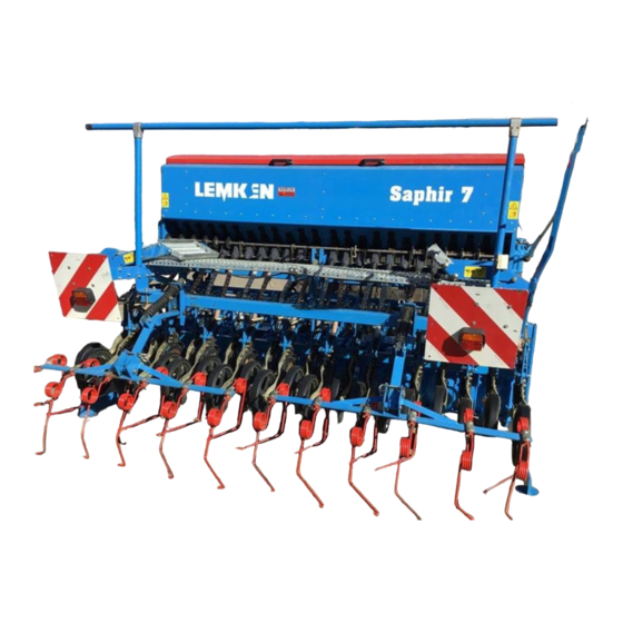
Seed drills
Saphir 7 DS
Saphir 7 ES
Saphir 7 S
SAFETY IS OUR CONCERN!
Art.-Nr.: 175 1447
GB-7/08.04
LEMKEN GmbH & Co. KG
Weseler Straße 5, D-46519 Alpen / Postfach 11 60, D-46515 Alpen
Telefon (0 28 02) 81-0, Telefax (0 28 02) 81-220
eMail: lemken@lemken.com, Internet: http://www.lemken.com
Advertisement
Table of Contents


Need help?
Do you have a question about the Saphir 7 DS and is the answer not in the manual?
Questions and answers