Renesas RX200 Series User Manual
Hide thumbs
Also See for RX200 Series:
- User manual ,
- Quick start manual (23 pages) ,
- User manual (25 pages)
Table of Contents
Advertisement
Quick Links
RX26T Group
Renesas RX Family
RX200 Series
All information contained in these materials, including products and product specifications,
represents information on the product at the time of publication and is subject to change by
Renesas Electronics Corp. without notice. Please review the latest information published by
Renesas Electronics Corp. through various means, including the Renesas Electronics Corp.
website (http://www.renesas.com).
www.renesas.com
MCK-RX26T User's Manual
Rev 1.00 May 23, 2023
Advertisement
Table of Contents

Related Manuals for Renesas RX200 Series


Summary of Contents for Renesas RX200 Series
- Page 1 All information contained in these materials, including products and product specifications, represents information on the product at the time of publication and is subject to change by Renesas Electronics Corp. without notice. Please review the latest information published by Renesas Electronics Corp. through various means, including the Renesas Electronics Corp.
- Page 2 General Precautions in the Handling of Microprocessing Unit and Microcontroller Unit Products The following usage notes are applicable to all Microprocessing unit and Microcontroller unit products from Renesas. For detailed usage notes on the products covered by this document, refer to the relevant sections of the document as well as any technical updates that have been issued for the products.
- Page 3 Renesas Electronics disclaims any and all liability for any damages or losses incurred by you or any third parties arising from the use of any Renesas Electronics product that is inconsistent with any Renesas Electronics data sheet, user’s manual or other Renesas Electronics document.
-
Page 4: Table Of Contents
Renesas RX Family MCK-RX26T User's Manual Contents Overview ..........................5 Presupposition and precautions of this document .................. 5 Product Contents ........................6 Product Order Information ....................... 6 Hardware Configuration and Default Setting ................7 Hardware configuration ........................... 7 Block diagram ............................11 Board Layout ............................ - Page 5 Renesas RX Family MCK-RX26T User's Manual 6.1.2 On-board debugger ..........................28 6.1.3 Inverter board connector ........................29 6.1.4 Serial communication .......................... 31 6.1.5 Reset circuit ............................31 6.1.6 LED ..............................32 6.1.7 CAN Communication ........................... 32 6.1.8 SPI Communication ..........................32 6.1.9...
- Page 6 Renesas RX Family MCK-RX26T User's Manual Figure of contents Figure 2-1 Product contents ..........................6 Figure 4-1 MCK-RX26T block diagram ......................11 Figure 4-2 Inverter board Layout ........................12 Figure 4-3 CPU Board Layout ......................... 12 Figure 4-4 Communication board Layout ......................13 Figure 4-5 Standoffs and Screws assembly ....................
- Page 7 Renesas RX Family MCK-RX26T User's Manual Table of contents Table 4-1 MCK-RX26T specification (1/4) ......................7 Table 4-2 MCK-RX26T specification (2/4) ......................8 Table 4-3 MCK-RX26T specification (3/4) ......................9 Table 4-4 MCK-RX26T specification (4/4) ....................... 10 Table 4-5 Jumper pin setting of Invertor board ....................14 Table 4-6 Jumper pin setting of CPU board ....................
-
Page 8: Overview
Renesas RX Family MCK-RX26T User's Manual 1. Overview is a motor control evaluation kit. By using this product, motor control with MCK-RX26T MCK-RX26T be performed easily. MCK-RX26T has characteristics shown below. (1) Supports Brushless DC motor. (2) Supports 1-/2-/3-shunt current detection. -
Page 9: Product Contents
Renesas RX Family MCK-RX26T User's Manual Product Contents This kit consists of the following parts. 1. Inverter Board (RTK0EM0000B12020BJ) x1 2. CPU Board (RTK0EMXE70C00000BJ) x1 3. Communication board (RTK0EMXC90Z00000BJ) x1 4. Brushless DC Motor (R42BLD30L3) x1 5. Communication cable x1 6. -
Page 10: Hardware Configuration And Default Setting
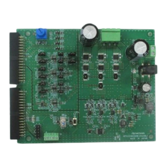
Renesas RX Family MCK-RX26T User's Manual 4. Hardware Configuration and Default Setting 4.1 Hardware configuration MCK-RX26T consists of the inverter board, the CPU board and the communication board. Specifications as a kit and for the relevant boards are listed below. - Page 11 Renesas RX Family MCK-RX26T User's Manual Table 4-2 MCK-RX26T specification (2/4) Item Specification Product name Inverter board RTK0EM0000B12020BJ Board part No. External view Note: The actual product may differ from this photo. 2 ways Power supply From DC jack or Power supply connector (DC 12~48V) *1 ...
- Page 12 Debugger E2OB (Onboard debugger circuit) Connector Inverter board connector USB connector for E2 OB SCI connector for Renesas Motor Workbench communication Through hole for CAN communication Through hole for SPI communication PMOD connectors Switch...
- Page 13 Renesas RX Family MCK-RX26T User's Manual Table 4-4 MCK-RX26T specification (4/4) item Specification Product name CPU Board Board part No. RTK0EMXC90Z00000BJ External view Note: The actual product may differ from this photo. Mounted MCU Product group RX72N group Product No.
-
Page 14: Block Diagram
Renesas RX Family MCK-RX26T User's Manual 4.2 Block diagram SCI connector Figure 4-1 MCK-RX26T block diagram R12UZ0111EJ0100 Rev 1.00 Page 11 of 38 November 15, 2022... -
Page 15: Board Layout
Renesas RX Family MCK-RX26T User's Manual 4.3 Board Layout Figure 4-2 Inverter board Layout Inverter board connector (for INV2) Inverter board connector (for INV1) Serial communication connector Reset SW RX26T USB type-C connector T/H for CAN PMOD T/H for SPI Figure 4-3 CPU Board Layout R12UZ0111EJ0100 Rev 1.00... -
Page 16: Standoffs And Screws
Renesas RX Family MCK-RX26T User's Manual Figure 4-4 Communication board Layout 4.4 Standoffs and Screws Before using this product, assemble the included standoffs and screws as shown below. Figure 4-5 Standoffs and Screws assembly R12UZ0111EJ0100 Rev 1.00 Page 13 of 38... -
Page 17: Jumper Pin Setting
Renesas RX Family MCK-RX26T User's Manual 4.5 Jumper pin setting 4.5.1 Inverter board Default settings and functions of the jumper pins (JP1~JP15) are as follows Table 4-5 Jumper pin setting of Invertor board Function JP No. Default setting 1-2pin short : Disable 5V regulator... -
Page 18: Cpu Board
Renesas RX Family MCK-RX26T User's Manual 4.5.2 CPU board Default settings and functions of the jumper pins (JP1~JP12) are as follows. Table 4-6 Jumper pin setting of CPU board JP No. Function Setting (function in use) Default setting open 1-2 short... -
Page 19: Communication Board
Renesas RX Family MCK-RX26T User's Manual 4.5.3 Communication board Default settings and functions of the jumper pins (JP1~JP3) are as follows. Table 4-7 Jumper pin setting of Communication board Jumper pin Default setting Function 1-2pin short : Enable pull-up for MD port (Not available) -
Page 20: Hardware Setup
Renesas RX Family MCK-RX26T User's Manual 4.6 Hardware Setup 4.6.1 Board Connection When using this product for motor control evaluation, connect the boards as shown in Figure 4-9. Note that the connector between the CPU board and the inverter board is a tight fit, so be careful not to bend the pins when connecting or disconnecting. -
Page 21: Power Supply
Renesas RX Family MCK-RX26T User's Manual 4.6.2 Power Supply There are three ways to supply power to the CPU board and inverter board, and the power supply for the communication board is independent of the CPU board and inverter board and is supplied at 5V from the USB connector. - Page 22 Renesas RX Family MCK-RX26T User's Manual (3) From USB connector 5V power is supplied from the USB connector (Type-C) on the CPU board. Use a USB adapter capable of outputting 1A or more so that the motor can be driven sufficiently.
-
Page 23: Inverter Board Specification
Renesas RX Family MCK-RX26T User's Manual Inverter Board Specification This section describes inverter board specification. 5.1 Functions 5.1.1 Inverter control circuit block The inverter board has the inverter control circuit block which controls the motor with 6 POWER MOSFETs. POWER MOSFET is controlled with 6-phase timer output of MCU. -
Page 24: Current Detection Circuit
Renesas RX Family MCK-RX26T User's Manual 5.1.2 Current detection circuit The inverter board has the current detection circuit to measure the current at the U, V and W phase. The current detection circuit uses shunt resistor at each phase. Voltage drop caused by the current flowing through the shunt resistor is amplified by the current detection amplifier to output. -
Page 25: Overcurrent Detection Circuit
Renesas RX Family MCK-RX26T User's Manual 5.1.3 Overcurrent detection circuit Detect the overcurrent from the input current, using the overcurrent detection circuit illustrated in Figure 5-3 If the current value is within the range of threshold, OC_INV_OUT is HIGH, and this changes to LOW if overcurrent is detected. -
Page 26: Output Voltage Detection Circuit
Renesas RX Family MCK-RX26T User's Manual 5.1.4 Output voltage detection circuit The INV-BRD has the circuit that inputs bus voltage and three-phase output voltage (U, V and W phase) into the AD pin of the microcontroller through resistive voltage divider. Relation between the three-phase output voltage, the bus voltage and the detection voltage is described by the below equation (3). -
Page 27: Led
Renesas RX Family MCK-RX26T User's Manual 5.1.6 The INV-BRD has three LEDs which the user can control. The LED ON/OFF is controlled by the pin state. Table 5-2 LED Connector pin LED1 LED2 LED3 ‐ ‐ CN4-18 HIGH ‐ ‐... -
Page 28: Pin Assignment
Renesas RX Family MCK-RX26T User's Manual 5.2 Pin assignment 5.2.1 CPU board connector Table 5-5 CPU board connector (CN3) Pin No. Output direction Signal SPARE1 AGND To CPU DC bus voltage detection AGND To CPU U-phase current detection To CPU... - Page 29 Renesas RX Family MCK-RX26T User's Manual Table 5-6 CPU board connector (CN4) Pin No. Output direction Signal To INV PWM W-phase (Lower) DGND To INV PWM W-phase (Upper) DGND SPARE2 SPARE3 SPARE4 SPARE5 To INV Bus power signal from CPU board...
-
Page 30: Hall Sensor Signal Input
Renesas RX Family MCK-RX26T User's Manual 5.2.2 Hall sensor signal input This product has connector for hall sensor signal input. Pin assignment of it is listed in Table 5-7. Table 5-7 Connector for hall sensor signal input (CN6) pin assignment Pin No. -
Page 31: Cpu Board Specification
(firmware) of RX26T with it. When you write a program, open (remove) JP11 and connect the CPU board to PC with USB cable. E2OB operates as debugger equivalent to E2 emulator Lite. If connecting from Integrated Development Environment or flash programing tool (e.g. Renesas Flash Programmer), set the type of debugger (tool) to “E2 emulator Lite”. -
Page 32: Inverter Board Connector
Renesas RX Family MCK-RX26T User's Manual 6.1.3 Inverter board connector Max 2 inverter boards can be connected to this product. 1st inverter board is connected with CN1 and CN2, and 2nd inverter board is connected with CN3 and CN4. The pin assignments of the connectors are shown in Table 6-1, Table 6-2, Table 6-3, Table 6-4. - Page 33 Renesas RX Family MCK-RX26T User's Manual Table 6-3 2nd inverter board connector (CN4) pin assignment Pin No. Pin Function RX26T Pin Pin No. Pin Function RX26T Pin AGND - (AVSS) P47/AN103 AGND - (AVSS) P44/AN100 P45/AN101 P46/AN102 P60/AN206 P61/AN207 P62/AN208...
-
Page 34: Serial Communication
Figure 6-2 Board connection of CPU board, INV board and COM board 6.1.4 Serial communication For serial communication using Renesas Motor Workbench, the CPU board has SCI connector. Pin assignment for SCI connector is listed in Table 6-5. Table 6-5 SCI connector (CN6) pin assignment Pin No. -
Page 35: Led
Renesas RX Family MCK-RX26T User's Manual 6.1.6 This product has 4 controllable LEDs, so that they can be used for program debug and the system. LED switches on when output from the corresponding port is “LOW” and switches off when output is “HIGH”. Pin assignment for corresponding LEDs is listed in Table 6-6. - Page 36 Renesas RX Family MCK-RX26T User's Manual Table 6-9 PMOD Type 3A connector pin assignment (CN12) RX26T port RX26T port PB4_CTS11# PB5_TXD11 PB6_RXD11 PB0_RTS11# Table 6-10 PMOD Type 6A connector pin assignment (CN10) RX26T port RX26T port PB3_IRQ9 PB1_SCL PB2_SDA R12UZ0111EJ0100 Rev 1.00...
-
Page 37: Rx26T Pin Function List
Renesas RX Family MCK-RX26T User's Manual 6.2 RX26T pin function list Table 6-11 RX26T pin function list Pin number RX26T pin function Signal function MTIOC9D / IRQ0 ENC_Z (INV2) / IPS_IRQN EMLE Emulator MD/FINED E2_on board/Emulator GTETRGA Overcurrent (INV2) IRQ1... - Page 38 Renesas RX Family MCK-RX26T User's Manual Pin number RX26T pin function Signal function GTETRGB Overcurrent (INV1) MTCLKA ENC_A (INV1) MTCLKB ENC_B (INV1) MTIOC0A / IRQ6 ENC_Z (INV1) / IPS_IRQN IRQ7 HALL_U (INV1) IRQ15 HALL_V (INV1) IRQ4 HALL_W (INV1) SW1 (INV1)
-
Page 39: Communication Board Specification
Power supply Power of this product is supplied at 5V from USB connector. 7.1.2 USB communication This product is equipped with a USB type-C connector for communication with a PC when using Renesas Motor Workbench, etc. 7.1.3 Serial communication This board has two SCI connectors for serial communication with the target MCU when using Renesas Motor Workbench, etc. -
Page 40: Design And Manufacture Information
Renesas RX Family MCK-RX26T User's Manual Design and Manufacture Information You can obtain information on the design and manufacture of this product from renesas.com Website and Support In order to learn, download tools and documents, apply technical support for RX family MCU and its kit, visit the below Web site. -
Page 41: Revision History
Renesas RX Family MCK-RX26T User's Manual Revision History Rev. Date Description Page Summary - 1.00 May 23, 2023 First edition R12UZ0111EJ0100 Rev 1.00 Page 38 of 38 November 15, 2022... - Page 42 MCK-RX26T User's Manual Publication Date: Rev 1.00 May 23, 2023 Published by: Renesas Electronics Corporation...
- Page 43 MCK-RX26T User's Manual R12UZ0111EJ0100...
Need help?
Do you have a question about the RX200 Series and is the answer not in the manual?
Questions and answers