Table of Contents
Advertisement
Quick Links
Advertisement
Table of Contents

Related Manuals for Major tech MT476


Summary of Contents for Major tech MT476
- Page 1 INSTRUCTION MANUAL MT476 690V VOLTAGE TESTER...
-
Page 3: Table Of Contents
Contents Page no 1. Safety Warnings................4 1.1. International Safety Warnings...........4 1.2. Safety Notes................4 1.3. Data Hold Button..............4 1.4. Warnings................5 2. Specifications..................7 3. Voltage Tester Description..............8 4. Explanation of Symbols..............9 5. Inserting/Changing the Batteries............9 6. Measuring Point Lighting..............9 7. Carrying Out Measurements.............10 8. -
Page 4: Safety Warnings
1. SAFETY WARNINGS 1.1. International Safety Symbols Warning of a potential danger, comply with instruction manual. Caution! Dangerous voltage. Danger of electrical shock. Double insulation. 1.2. Safety Notes • Reference. Please use utmost attention. • Do not exceed the maximum allowable input range of any function •... -
Page 5: Warnings
technical limits) able to distinguish operating voltage from interference voltage and has a means to directly or indirectly indicate which type of voltage is present. 1.4. Warnings The voltage detectors are designed to be used by skilled persons and in accordance with safe methods of work. The hand should not exceed the stop position when operating. - Page 6 Ÿ The equipment shall be in the specified range (see technical specifications) and voltage does not exceed the range of 690V. Ÿ Ensure the function of the equipment in good condition before use. Ÿ To ensure that the tester is normal operation, please measure a known voltage value.
-
Page 7: Specifications
2. SPECIFICATIONS Range Function LCD display 1999 counts (3 1/2 digit) LCD display with bargraph & backlight Voltage range 6, 12, 24, 50, 120, 230, 400, 690V AC/DC Resolution 1V AC/DC Tolerances DCV: + 1.0% of reading +3 digit ACV: + 1.5% of reading +5 digit 400VAC Max. -
Page 8: Voltage Tester Description
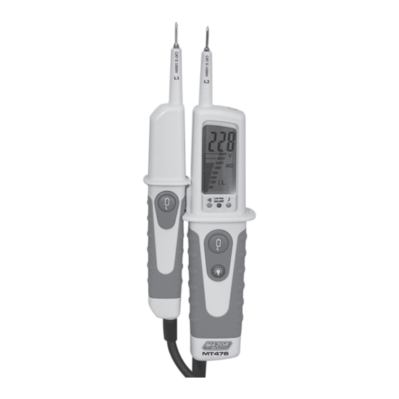
3. VOLTAGE TESTER DESCRIPTION 1 - Handle test probe - (L1) 8 - LED for continuity 2 - lnstrument test probe + (L2) 9 - Low impedance switch (L2) 3 - Measurement point illumination 10 - Measurement point lighting 4 - LEDs for voltage display Button 5 - LED for single-pole phase test 11 - Battery case... -
Page 9: Explanation Of Symbols
4. EXPLANATION OF SYMBOLS The voltage tester shows the following symbols: DC voltage AC voltage DC voltage negative potential (DC) Phase display from 100 to 690V - 50/60Hz when used as a "single-pole" phase tester. Continuity test symbol Rotating field display clockwise Rotating field display anticlockwise Device for work to be performed with voltage present Battery replacement symbol... -
Page 10: Carrying Out Measurements
7. CARRYING OUT MEASUREMENTS The twin-pole voltage tester has two handles, a connecting cable and an LCD display. Always hold the voltage tester in such a way that you get a vertical view of the display. Strong incidence of light may have an adverse effect on the display. -
Page 11: Rotating Field Direction Display
The applied voltage is shown on the LCD display. The Low-Imp LED signals low impedance measurement. The maximum permitted duty cycle in low impedance operating mode is 5 seconds for voltages up to 250V and 3 seconds for voltages up to 690V. -
Page 12: Continuity Check
10. CONTINUITY CHECK The voltage tester can also be used as a continuity tester. Always hold the voltage tester by the handles designed for this purpose. Never touch the device beyond the handle ends. The continuity tester switches itself on automatically when the test starts, and switches itself back off when the test has been completed. -
Page 13: Maintenance And Disposal
12. MAINTENANCE AND DISPOSAL Check the technical safety of the voltage tester regularly. It can be assumed that risk-free operation is no longer possible if: • there is visible evidence that the device has been damaged • the device has been stored under unfavorable conditions for a longer period of time •... - Page 16 MAJOR TECH (PTY) LTD South Africa Australia www.major-tech.com www.majortech.com.au sales@major-tech.com info@majortech.com.au...
Need help?
Do you have a question about the MT476 and is the answer not in the manual?
Questions and answers